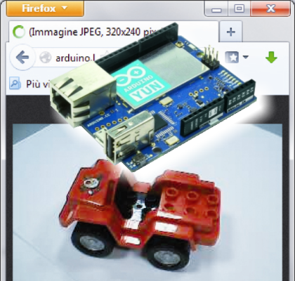
Let’s capitalize on the Yun Arduino new features to create an electronic “guard dog”, which allows you to watch your stuff, a hidden corner of the backyard or our car silently laying in the garden.
Here we wanted to face a small project, but one you would not be able to do with old Arduino boards. Connect a webcam, being able to display images on a web browser and activate actions if “something” or “someone” moves into the field that we want to hold on check. After an event trigger we could be alerted by Twitter, reusing the example proposed, or by e-mail, or even with the lightening of a notification LED.
As previously said on this blog, Arduino YUN forces you to pay attention to the software architecture and the general design that you want to accomplish. Especially to breaking the app into modules and defining the interaction and communication between them is key. The application is based on an existing infrastructure, consisting of the operating system and collections of ready-made programs to perform many of the functions that we’re going to realize. Once you designed your wannabe application, the first step is always to check for existing components. We will make the code only for parts that are specific to the application. This approach is made possible by the presence of the GNU / Linux operating system and thank to the collection of ready-made programs, that are available under various licenses with open source distribution. This is always more true also for the Arduino board section, for which more and more ready libraries and examples of applications are available. Attention must also be paid to the communication between the different components of the application, that “run” competing on processors: if you can have only one for Arduino, the GNU / Linux section could run several ones. The communication interfaces between processes must be designed, and coordinated according to the application needs, to avoid conflict situations in the use of shared resources.
Description of the project
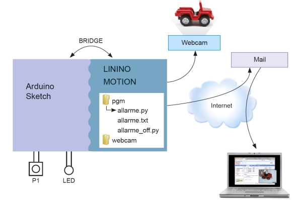
The webcam is connected to the USB port of the Atheros AR9339 processor. With regards to software we use the motion package, specifically designed for motion recognition. To let the operating system Linino see the camera, we also need to load the device driver. The peculiarity in Linino is that the drivers can be added on the fly, without the need of reconfigure and recompile the kernel modules of GNU / Linux. The motion package allows us to create a stream of the camera scenery, which is made visible via browser. Every time a movement in the scenery is spotted, we a series of frames gets recorded, catching the intruders and we want to be notified both by sending an e-mail to our address and by the lighting of a LED (which remains lit until we deliberately turn it off, pushing a button). You could also be notified with a tweet (by using the sketch presented long ago, with some modifications). For the notification we have chosen to use the features made available by the Bridge architecture. After the notification arrives from Linino we modify the contents of a file called “alarm.txt” from “0” to “1”. A kind of “traffic light”. The sketch running on Arduino periodically reads the contents of the file and if it finds a value of “1” it will turn on the red LED connected to pin 4 of the Arduino. Again, if the value in the file is “1”, the execution of a program on Linino that brings to zero the contents of the file is required. The red LED is turned on until it is switched off deliberately by pressing the button connected to pin 5 of the Arduino. At the same time the python program that sends us e-mail is launched.
The construction
The realization of this project allows us to examine some aspects of the administration of the Linino operating system. First, however, we realize the simple circuit shown in figure. We made the circuit on a breadboard.

Coming back to the “Software” part, the available tool is LuCI, the application with a web interface, which provides us with a menu of features, organized by topic, including the package management tool. In Linino we can also use the command-line interface, in this case using the package manager opkg, the equivalent of APT in Raspberry Pi, but it is also good to introduce the tools with graphical user interfaces that, when available and well-made, make the life easier for users. One additional note before we begin: on Arduino Yun the Linino operating system, like its progenitor OpenWRT, is installed on the NAND memory device, a 64Mb memory which leaves few space for the additional packages loading but thankfully sufficient for motion. Once the the board is conneced to the Ethernet network we await the full boot of Arduino Yun (lasts about half a minute), much longer than that of a normal Arduino board. Open the browser and type the address:
http://arduino.local
We’ll give “Arduino” as a password and enter the LuCI application. Click on the blue button “Configure” and then, on the next page, on the link “advanced configuration panel (LuCI)”.
The following page appears where we select the “Software” entry from the “System” menu.

In this way we enter the software packages management page. We can see the free space for the installation of new packages. Scrolling down the page you can see the list of installed packages.

First, let’s update the list of available packages clicking the button “Update lists”, the equivalent of the command “opkg update” given from the command line. Once the update of the available packages catalog is there, we can install the webcam driver. Insert the package name “kmod-video-uvc” in the text field to the right of “Download and install the package” label and click on the “OK” button. With the same procedure we install the “motion” package. After this installation we need to configure the package.

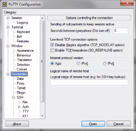
In order to do this we must enter into the heart of the file system to configure the “motion” package and the best way is using SSH. SSH (Secure Shell) is the remote access service normally used by GNU / Linux administrators to manage systems connecting from an external PC. The service is active by default on Linino, while we have to use a PC to install its client programs. We remind that the packets to be found are Putty and WinSCP. They could be found with a simple web search, are open source and free to use. Once installed they must be configured to connect to Arduino Yun. First we launch the Putty program, configure it and connect to Arduino Yun.
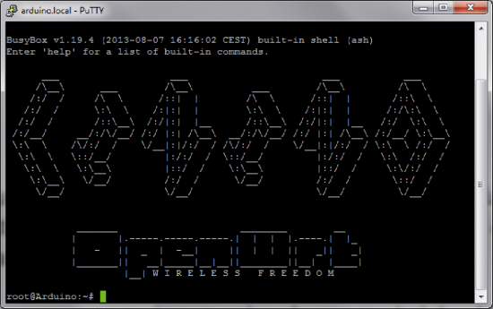
Login credentials would be required. “root” is the user to be used for login and “arduino” is the password. We will get the welcome page of the Linino shell:
Now connect the webcam to the USB-A (the big one), connected to the Atheros processor hosting Linino and issue the command:
dmesg
at the bottom of the list we’ll see if the webcam has been recognized.

Now give the command:
lsusb
and verify that the webcam is recognized as USB device

We can control with which file name (device file) the webcam is recognized, usually it’s video0. Launch WinSCP, the file manager which uses the SSH protocol. Configure WinSCP.


Go to the directory /dev and look for a file named video0, this is the device file that identifies the webcam. Now, always using WinSCP, configure the motion packet. Let’s go to the folder /etc/ and click on the file name motion.conf . a text editor with the configuration file contents would be opened.

Of all the long list of configuration parameters we analyze and configure those needed for the package first start. All other parameters can be configured later.
; area_detect value
If we do not specify anything, the whole area covered by the webcam will be analyzed to detect any movement. If we want to supervise only a portion of the imagine we can set it with this parameter. The area is divided into 9 parts designated as in figure.
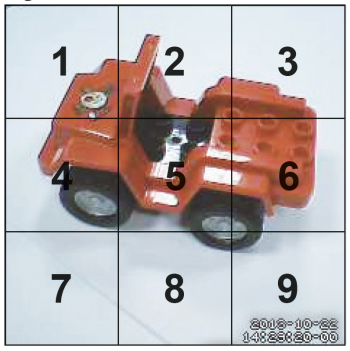
To activate the motion detection in certain areas we have just to include the corresponding numbers in the parameter, of course, after having removed the “;” comment. For example, to identify a movement in the middle of the image, from top to bottom, using the configuration:
258 area_detect
For the moment we leave things as they are so that all the area captured by the camera is analyzed in order to recognize a movement.
Now, go to the configuration parameter:
target_dir /usr/local/apache2/htdocs/cam1
This parameter contains the default folder in which all the images captured by the camera are stored. The default configuration is set to save only the images collected during the interception of movement, so you can recognize the intruder, in retrospect. If you leave the default folder, the images will be written on the NAND memory of Arduino Yun. Given the small size of the memory in a few minutes the stored images will saturate all the available space, undermining also the overall functioning of the Linino operating system. Not bad if it happens, usually just delete the file and restart the whole thing. At worst you can restore the original system with the reset button “WiFi reset button”, pressing it for more than 30 seconds.
Let’s replace the default configuration with the following:
target_dir /mnt/sda1/webcam
The parameter:
stream_localhost on
allows you to restrict the webcam streaming view only to local users, but that’s not our case as we connect with the browser of our PC.

So we enable external connectivity by changing the configuration parameter:
stream_localhost off

In the same way we modify the parameter that prevents external users to access the web motion server configuration tool from:
webcontrol_localhost on
to:
webcontrol_localhost off

The last configuration is used to let the alarm.py program run when motion is detected in the area controlled by webcam.
on_motion_detected “python /mnt/sda1/pgm/allarme.py”

Let’s now look at the event handling procedure that occurs when a movement is spotted in the area of the camera field configured as “sensitive” one. We just need to configure the following parameter: on_motion_detected to run a python program when an event is triggered.
To write the program always use WinSCP, go to the folder /mnt/sda1 and create a new folder “pgm”. Enter this folder and create a file named allarme.py, again by clicking the mouse right button and choosing “New” >> “File”. Save and expect to be asked for the password. Then copy in the program editor the lines from the Code1 (see below).
Save and close. Now open another file named allarme.txt, insert the value “0” (without quotes), save and close this file.
Finally create a final program named alarm_off.py, which will be recalled by the Arduino sketch to clear the alarm file contents. Copy the instructions in Code2.
Also, create another folder named “webcam” to store the frames of the movement recording.
Code1
#!/usr/bin/python

import os                      #Imports GNU/Linux comandi execution library

import smtplib                 #Importa mail sending library

from email.mime.multipart import MIMEMultipart   # Import mail attachments management library

from email.mime.text import MIMEText

# Openining the file in write (w +) + writing the value 1 and closes

fileout = open("/mnt/sda1/pgm/allarme.txt", "w+")

fileout.write( "1");

fileout.close()

# Click to look up the last frame stored in the folder / mnt/sda1/webcam

# to be sent as an attachment to the email

cartella = "/mnt/sda1/webcam"   #Importa la libreria per eseguire comandi GNU/Linux da pgm

os.chdir(cartella)

filelist = os.listdir(os.getcwd())

filelist = filter(lambda x: not os.path.isdir(x), filelist)

attachment = max(filelist, key=lambda x: os.stat(x).st_mtime)

# Set the headers of the email message

to_addr = "<Indirizzo_mail_mail_di_destinazione>"

from_addr = "<Indirizzo_mail_mail_del_mittente>"

# Titolo della mail

subject_header = "Allarme"

# Testo della mail

body = "Messaggio di allarme"

#set message object as MIMEMultipart

msg = MIMEMultipart()

# Begin to compose the message with the header

msg["To"] = to_addr

msg["From"] = from_addr

msg["Subject"] = subject_header

# Append the text of the mail

msgText = MIMEText('<plaintext>%s' % body, 'html')

msg.attach(msgText)

# Add the image as an attachment

fp = open(attachment, 'rb')

img = MIMEImage(fp.read(), name = "immagine.jpg")

fp.close()

msg.attach(img)

# sending the mail server

emailRezi = smtplib.SMTP("<server_email>", <porta_email>)

emailRezi.set_debuglevel(0)

emailRezi.login("<utente_mail>", "<password_mail>")

emailRezi.sendmail(from_addr, to_addr, msg.as_string())

emailRezi.quit()
Code2
#!/usr/bin/python

fileout = open("/mnt/sda1/pgm/allarme.txt", "w+")

fileout.write( "0");

fileout.close()
The first program is the most complex, especially in consideration of the “classical” Arduino logic. It allows us, in addition to “turn on the traffic lights” of movement interception, by bringing the contents of the file”allarme.txt” to the value “1”, to send an e-mail to our e-mail address with the event notification and attached the last frame taken during motion detection.
Let’s look now to making the sketch for the Arduino. The sketch uses the “Bridge” library and the managing files methods available on the SDCard.
Logical diagram of the sketch visible in code3 includes the following steps.
The beginning of the program includes the libraries that expose the objects that we will use in the program, or the ”Bridge” library for the management of communication bridge and the FileIO library for the management of the files resident in the Linino file system. We define pin 4 of the LED and the configure it as output and pin 5 as connected to the button.
In the setup() function we find the statement Bridge.begin() which initializes the communication “bridge” between the two sections of the board, de facto invokes loading and execution of management programs of the communication bridge in Linino environment. The instruction FileSystem.begin() executes the programs to make the Linino file system available to the Arduino sketch. In loop() there’s the main program logic. Allarme.txt file is opened in reading mode and the content is read. It should be emphasized that the method read () reads the file contents one byte at once. In our case we do not use a loop because the file is, precisely, one byte long. Close immediately the file so as not to interfere with any writing request from motion server. The contents of the test file follows. A value “1” means that a movement was intercepted by the motion server. In this case, the red LED lights up and proceeds to set the file allarme.txt contents to value “0”. In this we send to the Linino a command that requires the execution of the python allarme_off.py program directly into the Linino environment. That writes “0” in the allarme.txt file. The reasons are, on one hand, to present in the same post the most important Bridge feature, on the other to use a file reset mode that interferes as little as possible with the general operation of our application. We remind that the motion server is always looking for movements and notify us by writing in the allarme.txt file. These potential conflict must be taken into account during the design of embedded applications as a source of intermittent and malignant errors, difficult to detect and remove. A two-second delay allows to not choke the communication “bridge” between Arduino and Linino too much.
Code3
/ *

Sketch for the management and reporting movements from motion

* /

#include <FileIO.h>

#include <Process.h>

int led_rosso = 4; // LED motion detection

int buttonPin = 5; // reset LED button

char buttonState = 0;

String stato = "";

void setup() {

 // Setup Bridge bridge.py on Linino

 Bridge.begin();

 pinMode(led_rosso, OUTPUT); // Sets pin 5 as OUTPUT

 // Setup File IO calls files.py on Linino

 FileSystem.begin();

}

void loop() {

 / / Instantiate object file and open the file in read

 File nome = FileSystem.open("/mnt/sda1/pgm/allarme.txt", FILE_READ);

 stato = "";    // Read a character from the file

 stato += (char)nome.read();

 nome.close();  // closes allarme.txt

 if (stato == "1") {  // If 1, motion was detected

    digitalWrite(led_rosso, HIGH);  // turns on the red LED

    Process zero_alarm;

    zero_alarm.begin("python");  // Linino Command

    zero_alarm.addParameter("/mnt/sda1/pgm/allarme_off.py"); // Parametri comando

    zero_alarm.run();

 }

 buttonState = digitalRead(buttonPin);

 if (buttonState == LOW) {         // If button is pressed

    digitalWrite(led_rosso, LOW);  // the LED is turned off

 }

 delay(2000); /

}
Now we can try everything: launch the motion program with the command:
Motion
At this point open a browser and type the address:
http://arduino.localhost:8081
In your browser you should see the image taken by the camera.

In a separate window type the url:
http://arduino.localhost:8080
so you can access the essential motion managing application: we get a page with the contents of figure.

Click on “All” and get the menu.
Start with action that presents the menu: with “quit” you can interrupt the server operation, re-initialize with restart, for example after changing the configuration parameters. Makemovie records the images taken from the camera while Snapshop save the current frame.
The “detection” menu allows to manage the motion recognition task, with “pause” and “start” we can turn it off and turn it back on.
Finally, “config“, lists the function , that allows to customize the on-line parameters, if you save it (“write”), the changes will be recorded in the motion.conf file, which we have previously modified by hand. “Get” and “set” allow to manage the individual parameters of the configuration file.

Now the test: let the camera intercept a movement, we will see the red LED lighting up and will find, in the folder mnt/sda1/webcam, a sequence of the related images.

Open your inbox and you will find the notification message with an image attached. Now that we have taken note of what happened we can reset everything by pressing the button on the breadboard, switching off the red LED. This project allows a huge variety of tests, with the variation of the motion parameters and event management through the Arduino sketch. You can experiment without any problems: in the case of “irreparable” situations, although quite difficult to achieve according to our experience, you can always use with the reset button.
Download program

[…] Let’s capitalize on the Yun Arduino new features to create an electronic “guard dog", which allows you to watch your stuff, a hidden corner of the backyard or our car silently laying in the garden. […]
[…] Let’s capitalize on the Yun Arduino new features to create an electronic “guard dog", which allows you to watch your stuff, a hidden corner of the backyard or our car silently laying in the garden. […]
[…] Boris Landoni from Open Electronics writes: […]
[…] Let’s capitalize on the Yun Arduino new features to create an electronic “guard dog", which allows you to watch your stuff, a hidden corner of the backyard or our car silently laying in the garden. […]
[…] Let’s capitalize on the Yun Arduino new features to create an electronic “guard dog", which allows you to watch your stuff, a hidden corner of the backyard or our car silently laying in the garden. Here we wanted to face a small project, but one you would not be able to do with old Arduino boards. Connect a webcam, being able to display images on a web browser and activate actions if "something" or "someone" moves into the field that we want to hold on check. After an event trigger we could be alerted by Twitter, reusing the example proposed, or by e-mail, or even with the lightening of a notification LED. As previously said on this blog, Arduino YUN forces you to pay attention to the software architecture and the general design that you want to accomplish. Especially to breaking the app into modules and defining the interaction and communication between them is key. The application is based on an existing infrastructure, consisting of the operating system […] […]
[…] Capitalise on the Yun Arduino new features to create an electronic “guard dog", which allows you to watch your stuff, a hidden corner of the backyard or our car silently laying in the garden. […]
Ok, not all is working, I have to check some details, cause I use a Yùn shield instead of a Yùn, so I don’t have a Built on SD card reader and I must use a USB hub and stick instead SDCard. So my sda1 is sdb1 instead. Bref, little details.
But, I must admit that the camera started right away and I can see the picture on the port:8081, using the web page AND VLC. Just for that I must say WOW! Thank You so much you made my holidays :)
Other ways, I will work on that, and post my results when I get for people that use the Yùn shield.
By the way, your explanaition are very clear, I was affraid that I had to buy some fancy web cam to do this project, according to the Arduino and Adafruit web site very few kind of web cam work with OpenWRT, and you prove them wrong since I’m using a 2$ web cam from the dollars store lol.
Once again, thank you Happy holiday, give you news soon.
I have a problem with bridge taking the files above it Arduino: 1.5.8 (Windows 8), Board: “Arduino Yún”
Bridge.ino:1:1: error: expected unqualified-id before ‘/’ token
Error compiling. Also it will not let me connect to yun on web page as http://arduino.localhost:8081 .
HELP!!!!