
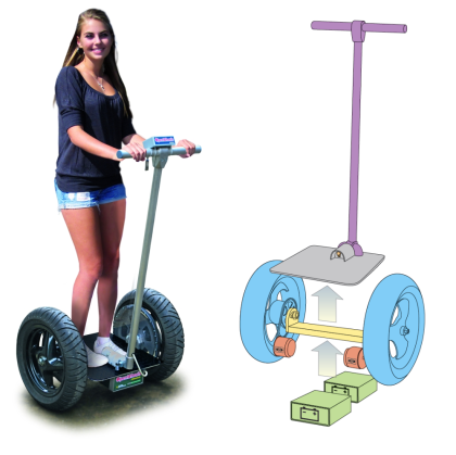
The series of posts devoted to the OpenWheels platform continues with the description of the processes related to the verification and management of the data collected from the sensors through a dedicated telemetry software .
At this point in the project, OpenWheels board is widely tested and ready to work with its firmware. It seems logical to expect that the firmware will undergo improvements over the course of time, which is why this first version will be called OpenwheelsV1.0. The firmware consists of seven files – each developed for a specific function – assembled by the compiler during the loading phase of the microcontroller. In case of programs with a large number we prefer to break the code into subroutines, each in a separate file: in this way the reading of the code is simplified and the modification of a single part of the code involves just one file. Obviously, it is necessary the software to be designed for this, making sure that the changes to a module will not affect the function in others. The seven files that make up the firmware with their descriptions are listed in table:
| module name | Function |
| EEPROM | in this module you see the features for managing writing and reading on the non volatile memory of the ATmel328. |
| IMU | This code is necessary to process the data from the inertial module: the analysis of the values from the accelerometer and the gyroscope. |
| Motor | in this part you’ll find features regarding PWM module setup and control of the duty-cycle engine . |
| OpenWheels | The module with the definition of the variables, the main loop processing and management of the LCD. |
| PID | is the code for processing the stabilization. |
| serLCD | module containing the instructions for the management of serial LCD display. |
| Telemetry | module containing the functions for sending and receiving telemetry data. |
It is a little less than nine hundred lines of code optimized to achieve a lean and fast program, despite having to perform several operations with the small 8-bit microcontroller clocked at 16MHz only. In general, as a philosophy, the focus was on the use of variables of float type only when strictly necessary and, where possible, we used direct access to registers using assembler instructions that can reduce the code by increasing the speed. Oddly enough, the lines looking after OpenWheels stabilization are not many, while the management of telemetry and LCD display takes several lines.
As you know, the firmware has already been analyzed in a more specific article available here, now we deal with telemetry and latest tests.

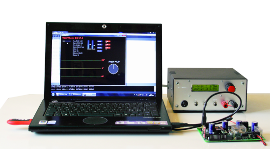
Once the firmware is installed, the board is fully operational and OpenWheels telemetry is already active; the latter can be used by connecting the board to a PC via the normal programming system (cable + USB / serial adapter). Yhe XBee is not installed on the OpenWheels and the JP6 jumper is left open.
We need to turn on the application written Processing language on the PC – called OpenWheels GUI (Graphic User Interface) – which can handle the communication with the board. Being written in Java, it requires no installation: simply copy the files to a folder and run the application; is compatible with both Windows and Linux. For proper operation it is necessary to start the OpenWheels board and wait at least 5 seconds, so that the initialization steps complete, then you can start the software for telemetry. On the left there is a drop down menu for selecting the serial port to be used, this must correspond to the COM assigned by the USB / Serial (or USB / XBee) adapter. This test can also be done before installing the board on the OpenWheels, provided THAT both the gyroscope, and accelerometer are connected.
This interface provides direct information on the sampling of the accelerometer and gyroscope, and makes it easily interpretable thanks to a graphical data representation in real-time. To take advantage of this method of analysis it would be appropriate that the board was vacated and separately powered by a power supply, so it would be easily adjustable.
This software, as well as that of the board, experienced remarkable improvements: the very first version consisted only of reading the IMU module to verify the correctness of the algorithms implemented in software.
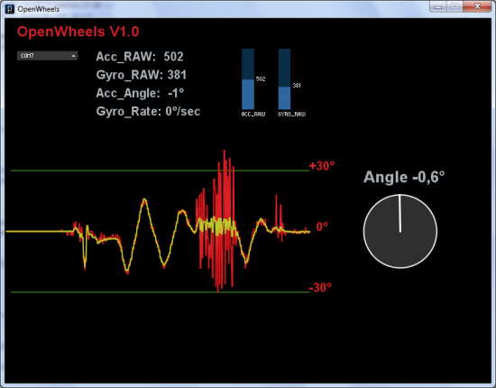
In figure you can see the red trace related to the accelerometer while the yellow one is that of the measure of the angle, realized by the complementary filter. By simulating a OpenWheels jump, quickly waving the board to see how the mathematically calculated angle behaves; as you can see, the measure of the angle is very clean.
The graph is of the Roll-mode type, such as those used by cardiac monitors, because it allows for a clear instantaneous view and also shows the past state of the variable; simply sending data to Arduino Serial Monitor would not have been so useful.
If you install the board on the OpenWheels mechanics and want to see the telemetry data, you should equip yourself with an on board netbook with the obvious discomfort (and danger) of reading the data as you move; For this reason we have provided a wireless telemetry system via XBee module. For this mode of functioning, you have to purchase two XBee modules; any version except PRO which, being too long don’t actually fit into the card. A USB / XBee interface is also necessary to interface one module to the PC.
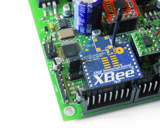
NOTICE: When using telemetry with the XBee modules you need to short the JP6 jumper which, however, must be left open during the programming; This avoids a conflict between the XBee module and the USB-Serial adapter.

Whilst the Series 1 modules can be used directly without any programming, the Series 2 modules require setting some parameters: this is because in a XBee system there must be at least a coordinator and an end-device.We are interested in programming the modules so that they support the mode called transparent mode, ie a communication capable of replacing a normal wire connection, furthermore we also want the two XBee modules used in the project to communicate with each other, ignoring any other possible transmission.
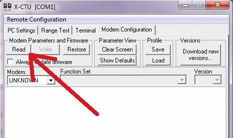
First thing first: download and install the software provided by the manufacturer of the modules, called X-CTU; if needed update the list of firmware modules. Let’s insert one of the two modules in the USB / Xbee adapter and connect it to the PC: now execute the Test/Query through the application to verify that the module is properly detected, then use the read function to read the parameters currently set up on one module.

Now just copy the identification number of the module (factory set and unique for each module) on a sheet of paper. These are the two values dubbed SH and SL.
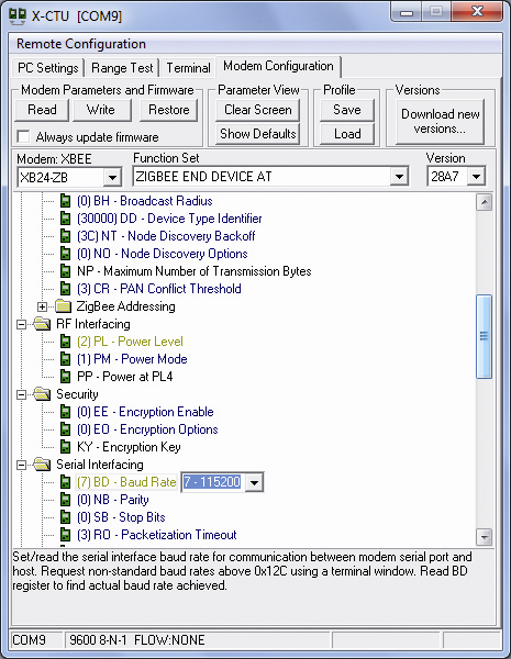
Replace the Xbee module and repeat the process on the other one and set fields as shown in table
| Parameter | Function | New value |
| FS | operation mode | ZIGBEE END DEVICE AT |
| DH | High target address | SH address of the other module |
| DL | Low target address | SL address of the other module |
| PL | power of transmission | 2 (medium power) |
| BD | speed of transmission | 7-115000 |

The power reduction is a precaution to prevent an excessive absorption in power that can overheat the small voltage stabilizer that provides 5volt on the OpenWheels board. Exchange again the Xbee module and set the new module as shown in table.
| Parameter | Function | New value |
| FS | operation mode | ZIGBEE COORDINATOR AT |
| DH | High target address | SH address of the other module |
| DL | Low target address | SL address of the other module |
| PL | power of transmission | 2 (medium power) |
| BD-speed | speed of transmission | 7-115000 |
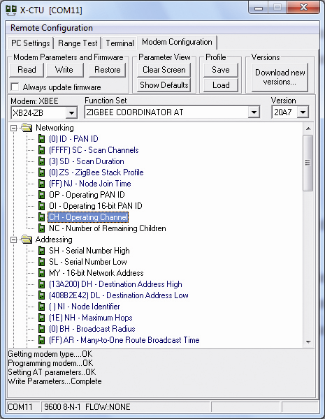

Verify that the ID field, the Personal Area Network identifier, is set to zero for both modules. Now the two modules can communicate only with each other, effectively replacing a physical serial connection at a speed of 115Kbps.
To better understand the capabilities of the telemetry we advise you to watch movies associated with this item. Two V-meter provide real time measurement of the accelerometer (Acc_RAW) and the gyroscope(Gyro_RAW);this allows to evaluate the amount of scale actually used in the measurements and if there are situations that lead to an out of scale. Telemetry also provides the value of the inclination with the only measure of the accelerometer (Acc_Angle) and the rotation speed obtained from the measurement of the gyro(Gyro_Rate).The Drive variable is the actual value sent to the motor control, while the Steer variable is the value of the steering. Even levels of voltage and current on the battery are shown by telemetry. On the right, the round indicator shows the angle calculated by measuring the fusion of the two sensors: this value is very accurate and also insensitive to external mechanical disturbances.
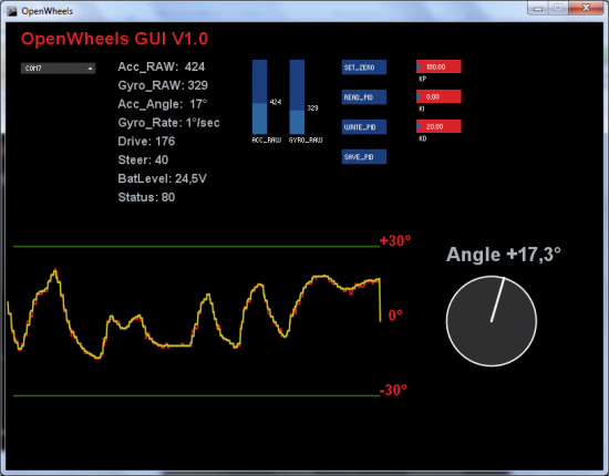
On the right side of the screen you will also find some useful buttons to remotely manage OpenWheels. The SET_ZERO function sets accelerometer and gyroscope zeroes; the measured value is automatically saved in the memory of the microcontroller and this avoids the need to set it every time you turn on OpenWheels. Setting the zero lasts a few seconds and requires that OpenWheels is perfectly vertical. The READ_PID function allows you to read the parameters of the PID control implemented on the firmware: they can be changed by clicking on the check box in red showing the value. After every change you need data to be sent to the microcontroller via the WRITE_PID command: saving in EEPROM memory is done by clicking on the SAVE_PID command.
When you first use the OpenWheels board, the values of the zeroes of the sensors have not yet been identified, it is then necessary to provide them; those values are indeed not recorded automatically during the ignition phase.
Now the first list of five posts about Openwheels are ready for you to: please find the whole list here!
Very soon we will release a dedicated collaboration page for you to download all the files in a centralized manner, to add your designs and tweaks, to make your own mods of OpenWheels! Stay tuned!

Thank you so much for sharing your knowledge Boris!
I feel excited to start by myself next month. Altough your quotes were very helpful I was wondering if you can provide us some exact numbers/measurements were to drill the holes for example in ‘pedana/staffa laterale/staffa motore’ etc. The size of these components are totally clear but I couldn’t figure out were to drill exactly.
Boris, please keep us posted with this stunnig project, thanks a lot for your reply and off course for the hard work!
Hi, here you can find the mechanicals parts http://www.open-electronics.org/openwheels-put-the-mechanical-pieces-togheter/