
Let’s add a graphic touch display to our Arduino-like boards, with dedicated hardware and three libraries.
After showing you four prototyping boards from the Fishino series (UNO, Fishino 32, MEGA, Guppy… and the fifth is on its way!), we started to feel the need to propose some electronics on the side. In particular, we felt the need of a display to match them, in order to complete the applications with visual outputs other than that simple on or off LEDs. But we weren’t happy with a simple text display (e.g. the really common 2 or 4-line alphanumeric displays based on the HD44780 controller), because we wanted a nice graphic display characterized by small dimensions and a decent resolution on which to show icons, symbols and some graphics. Therefore we started looking for something already available, however, we found out that although there are many displays (and shields supporting them) they have a lot of limitations.
This is why we wanted to create something custom made, a shield mounting a display with good performances, that we are going to describe in this article.
Let’s start from the beginning, from the project phase, by saying that we wanted something capable of satisfying the following:
- fairly small dimensions (2.for up to 3.2 inches);
- minimum resolution of 320 x 240 pixels, with high color depth;
- touch interface to interact with our Fishino;
- low hardware resources requirements for our board, in order to use it even with those Fishino models equipped with fewer I/Os (e.g. Guppy);
- a shield capable of adapting to all the products from the Fishino range and even too many from the Arduino serious, without flying connections;
- possibility to connect other components to the shield, therefore exposing of all the I/O’s to various boards even went mounting the display.
We think we managed to satisfy our goal almost to a full extent (we’ll see later some small “limitations” that can be easily overcome), with an interesting product that is really simple to use, and we are going to introduce it in these pages.
In order to make it even easier to use, we provided you with three dedicated libraries, two of which derived from Adafruit, which is capable of managing to display itself, and one completely developed by us for managing the built-in touch panel.
A “universal” Shield
Contrary to what we usually do, we will start the shield description… From the end! In fact, the most complex aspects of developing this project was creating the board’s layout, since we had to combine boards that are very different from each other. Therefore we started with the “graphical” development of the board then we moved backward up to the circuit diagram.
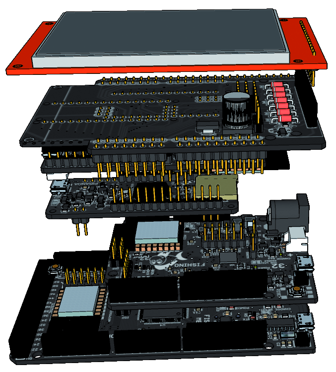
Let’s start from the encumbrance: the first requirement was to obtain a board with dimensions comparable to our Fishino UNO (but also to Fishino32 and Arduino UNO); therefore the display must be overlapped without increasing its lateral encumbrance, or at least increasing it just to a minimum: everything must be developed in the depth direction. Therefore we opted for a consistent “sandwich” in order, from TFT display to a shield and finally, to the microcontroller board; In figure does a better job of explaining this concept.

In this image you can see the mockup of the shield mounting a display and a Fishino MEGA, our starting base.
The need for being able to access all the I/Os of the board forced us to add, on the side, two rows of male connectors which are in parallel to those that must be inserted in the female connectors of the board, that can be accessed using the standard Dupont wires.
After sketching out the board’s layout, display’s dimension had been set to 2.4 inches diagonal, in order to respect the design encumbrance.
Another binding parameter for dimensions was the need to use the least possible numbers of I/Os; therefore we discarded all the displays with parallel interface (8-bit but also 16-bit) that would’ve basically required all the resources of the “smaller” boards so we moved towards a display with SPI communication that can be easily found in the 2,4 inches format.
This display uses the SPI pins (MISO, MOSI and SCK) along with the Wi-Fi module and SD memory cards (and more!), A selection line and a control line for the display and other 2 lines for the touch sensitive display, so four I/Os “exclusively” used instead of the minimum 10 to 12 for parallel interface models.
As we will see below, we later added some optional functionalities, which can be obtained by using a few other I/Os.
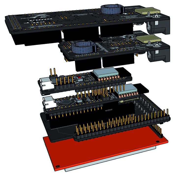
After deciding on a layout and display, we had to find a way to “squeeze in” on the board all the models provided on the same shield. Since the current technology allows it, we realized 3D models of every boards, the 3D model of the display and the initial 3D model of the shield, in order to graphically overlap them and notice possible interferences; in figures you can find the expanded bottom and top view drawings of our shield with a good number of Fishino boards overlapped. It is understood that only one Fishino can be mounted at a time.
We looked for the best placement for “small” boards (Fishino Guppy/Arduino Nano and the incoming Fishino Piranha, a pin-out compatible with Arduino MKR1000) in order to not have interferences between the connectors (which can’t be 100% avoided, as we’ll see shortly) and to respect planned encumbrance.
So here we see the final layout of the board, shown in the figure from the controller insertion site (i.e. the Fishino/Arduino board side).
So, everything’s perfect? Unfortunately, no, because Fishino UNO and 32 boards have auxiliary connectors, specifically the ESPCONN connector on the UNO and the ICSP connector on the 32 that interfere with the connectors of the “small” boards (Nano/Guppy and Piranha/MKR1000); they can be physically inserted but the signals are not compatible with the board circuits.
The issue cannot be solved since some connectors must have a definite place in respect to one another: for instance, the ISP connector that transmits the SPI signals book for the UNO and the Mega.
To solve the problem we have more than one option:
- we can mount just the essential connectors for the Fishino to be inserted, this is the solution we have chosen for this project, since we can suppose that the shield, although “universal”, is to be used with just one controller at a time; the disadvantage is that the shield, once set in order to support UNO/MEGA/32, cannot mount Guppy/Nano/Piranha and vice versa without replacing the connectors;
- we can mount all the connectors and get rid of just the interfering pins; this solution may be almost optimal, however, the signals corresponding to the eliminated pins would not reach the additional side connectors (someone might prefer the solution, so we are going to explain it in detail below);
- we can “turn” the ESPCONN and ICSP connectors of Uno and 32 boards on the opposite side of it; this solution solves everything, unfortunately, it requires a modification of the above-mentioned boards, by removing the connectors and soldering them again on the opposite side; this is a feasible solution, however, it requires good manual skills in order to not damage the boards.
As we mentioned, we opted for the first solution, especially considering that the shield will be provided in a kit, so complete with the connectors to be mounted; however, you can definitely choose another solution.
Circuit diagram
After studying the board’s layout, here we are, ready for the circuit diagram! Everything is fairly simple, it’s just a matter of connecting the various signals and plan out the bridges needed to adapt them to the various boards. In particular, this is necessary for Piranha/MKR1000 boards, which pinout is completely different compared to the others, as their corresponding interrupt/SPI signals.
The first weird thing we can notice in the circuit diagram is how all the active and passive components are doubled. This was done in order to create a board capable of mounting both SMD components, which is an advantage for industrial production, and THT components (with passing rheophores), in order to offer the board in a ready to assemble kit even to people without experience in terms of surface mounting. Therefore, in the diagram all the “double” components are meant as an alternative between SMD and THT format.
Let’s begin by describing the power section, which might seem superfluous (all the boards used have a 3.3 V power output), however it is crucial, given the current scarcity on some boards, especially on original Arduino’s and a lot of cheap clones.
It is a very simple 3.3 V low dropout linear regulator capable of providing an output just shy of 1 A, more than enough for the purpose.
The PWR bridge allows to select voltage coming from the internal regulator or directly from the 3.3 V line of the connected board. It might be superfluous but, by having a board with sufficient current available on 3.3 V, like the Fishino series, this allows us to save the U1 regulator and the capacitors if we want to limit costs to the maximum extent.
Now, let’s take a look at the TFT display connector and the related components, the visualizer used works at 3.3 V and requires corresponding logic levels; by providing 5.5 V levels, it can be easily damaged. To solve the problem, we inserted level limiters, each composed of a resistance (R1÷R8) and a diode connected facing the positive terminal of 3.3 V voltage. This allows to “discharge” on the 3.3 V and a signal beyond that value and limit it automatically.

The resistors chosen have two opposing requirements: they must be big enough in order not to absorb excessive current and at the same time low enough in order not to cause a delay for quick signals. As you can see, in the enabling and control lines (IRQ, DC and the two CS) where signals are “slow”, resistances have a value of 1 KΩ, thus favoring low current in spite of response speed; on the other hand, in the three lines where SPI signals travel, which can reach frequencies over 10 MHz, we opted for a sensibly lower value of 150 Ω. Even at this value, it is hard to go over 12 to 16 MHz, in fact we limited the SPI signal frequency at 12 MHz in the library, more than enough to work at decent speed.
The MODE connectors (and JP14, mounted next to the board) are used to select the use with “standard” boards (UNO, MEGA, 32 and similar) or Piranha/MKR1000 type boards with different signals.
Even JP16/17/18 connectors are used for controller selection, and more precisely in order to manage the different position of SPI signals on the boards.
As an additional optional, we have inserted some bridges on the PCB in order to disconnect the 4 control lines of the display: SJ_T_IRQ, SJ_T_CS, SJ_DC e SJ_CS. What are they for? To put it simply, over time we realized that oftentimes the shields, having preset connections to digital pins, are very limiting. If you need to connect something else that uses the same I/Os (e.g. another shield in cascade) things can get complicated and you can’t choose not to use shields together or to cut out some of the PCB’s tracks. By cutting out these bridges, on the other hand, you can free the corresponding I/Os without the need to tamper with the printed board; naturally, it is then necessary to create some flying connections with other I/Os to use display, but this is a very simple thing to do.
The Q1 MOSFET, along with the R1 resistance and the LEDSW connector is optionally used for controlling the display’s backlighting. By leaving it open, the MOSFET is polarized by R1, therefore, backlighting is on; if you insert a jumper you can control it through a digital I/O of the controller, more precisely the D8 on boards UNO/MEGA/32 and D3 on Piranha/MKR1000.
Thanks to this feature we can save current when the display does not need to be on.
Then, we can see the two RESET and WAKE buttons that are use respectively to reset the controller (more user-friendly than having to “look for” the button on the board which, especially on the MEGA, it’s hard to reach) and to “wake” it up, or for other uses at your choice. The WAKE button is in fact connected to the same interrupt line of the touch controller and can, therefore, be used to exit standby even when the display is completely off.
After that, we also wanted to insert a buzzer in order to have a sound feedback, both on display touch and possible error statuses. The buzzer is (optionally) connected to another digital I/O, and more precisely to the D9 on boards UNO/MEGA/32 or to D4 on Piranha/MKR1000, also selectable through a connector, the BUZSW. If we leave the connector open we save one I/O line but we can’t make use of the buzzer.
The latter is passive, therefore it must be piloted with a PWM signal of the right frequency, managed by software.
Finally, we can see the track of SPI signals and the last board selection connector, the SPI-GUPPY. As we already mentioned, SPI signals travels on different I/Os based on the boards. On UNO and Mega (and Fishino 32) this is easier thanks to the ISP connector which transmits them despite where they are connected; this is done through the JP9 connector that gathers those signals.
We’ve already seen the corresponding jumpers on Piranha/MKR1000 boards. Guppy and Arduino Nano are left out which, despite having the ISP connector, they have it on the “wrong” side of the board, therefore it cannot be used in our shield. If we mount Guppy or Arduino Nano we, therefore, have to insert three jumpers in the SPI-GUPPY connector in order to create the required connection to the SPI lines.
Practical construction
Making the shield is something that can be done even by those without much experience, thanks to the possibility to mount traditional discrete components. However, if you prefer, you are more than welcome to use SMD components.
We always recommend to mount low profile and low encumbrance components first, then resistors and diodes, followed by an electrolyte capacitors, tension regulator, and the MOSFET.
After that, you are going to place the buttons and the buzzer and, lastly, the connectors, since they take up quite a lot of space.
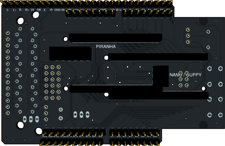
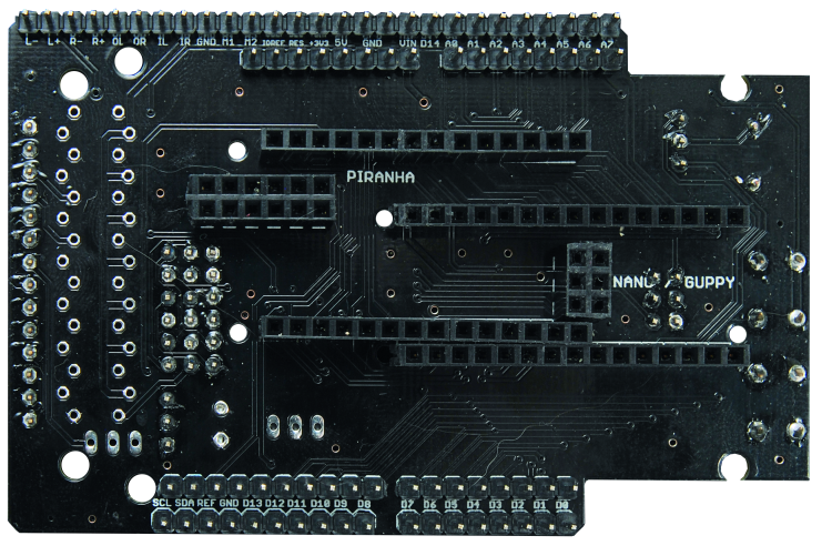
Below you can see two images of the shield, both from the top (passive/active components, jumper and TFT display connector) and from the bottom (board connectors).
The last thing we must pay attention to is the mounting side of the various headers; by mounting them on the wrong side you, of course, won’t be able to add controllers, jumpers or the display!
As previously mentioned, due to some interferences between the various connectors of the boards that can be used with our shield, we cannot mount all connectors simultaneously, without taking particular precautions. You will remember that we provided 3 possibilities, the third one involving a modification to the original control board that we, however, leave to those with good manual skills.
The other two alternatives are to either mount just the necessary connectors for the boards you’re going to use, option that doesn’t need further explanations, or to eliminate the interfering pins from some connectors, thus making the shield usable with any board, although it won’t be able to transmit some of the available signals outside.
Below, we see the interferences and the pins to get rid of.
Use with Fishino32
Fishino32 board interferes with Guppy/Piranha board connectors in only two points, shown in figure .

By avoiding to mount the connector in the two points shown you can completely solve any interferences, although you won’t be able to bring the VIN of the PIRANHA on the outside, same goes for the D4 on the Guppy board. VIN is needed only if you power the board with external voltage, while D4 of the Guppy, being also used by the internal SD memory card, is probably useless for external use.
By eliminating these two “segments” of connector you are then able to also mount the following boards without interferences: Arduino UNO, MEGA & Nano, Fishino MEGA, Fishino32, Fishino Guppy, Fishino Piranha and Arduino MKR1000. Fishino UNO board suffers other interferences that we are going to describe in the following paragraphs.
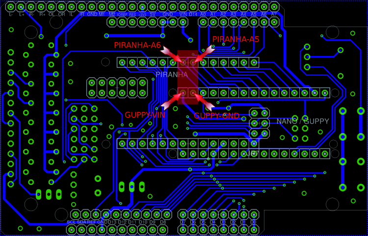
Use with Fishino UNO
Fishino UNO board interferes with Guppy/Piranha board connectors in four points, shown in figure.
In this case also you can make our TFT shield “universal” by eliminating the pins of the connectors indicated by the arrows in the above-mentioned figure. However, in this case we have to sacrifice external connections of the two analog channels A5 and A6 of PIRANHA and the Guppy’s VIN. A GMD line is also present on another pin so it won’t cause any problems.
By eliminating these four pins it is also possible to mount the following boards: Arduino UNO/MEGA/NANO, Fishino UNO, Fishino MEGA, Fishino GUPPY, Fishino PIRANHA, but not the Fishino32 which requires getting rid of the pin mentioned in the previous paragraph.
If you make both modifications you can, of course, mount all available boards.
And now… Software!
As previously mentioned in the intro, we set up three libraries for the shield that allows to control it completely. These are:
- FishinoGFX, basically an identical version to the Adafruit counterpart, managing graphic functions “at high level”;
- FishinoILI9341, managing interface function with the display and hardware level; this library too was developed starting from the Adafruit counterpart, although with some substantial modifications;
- FishinoXPT2046; managing touchscreen, written from scratch by us.
Let’s start from the display section, with a very simple sketch that initializes the display and draws a bicolor cross; you can find it in List 1.
listing1
#include <SPI.h>
#include <FishinoGFX.h>
#include <FishinoILI9341.h>
// This line is for convenience, so you do not have to write
// FishinoILI9341 at each command sent to the display
#define tft FishinoILI9341
void setup()
{
// Initializes the screen
tft.begin();
// Erases the background filling it with black
tft.fillScreen(ILI9341_BLACK);
// Draw a cross that runs through the screen
// in two colors
tft.drawLine(0, 0, tft.width(), tft.height(), ILI9341_RED);
tft.drawLine(0, tft.height(), tft.width(), 0, ILI9341_GREEN);
}
void loop()
{}
As you can see, the sketch is very simple. The loop() is empty (there is nothing to loop!), While everything takes place in setup().
The first line of this function:
tft.begin();
Initializes the display. By using the shield with the provided boards you don’t have to specify connection points; library will take care of everything. If you want to use different connections, you must specify which I/Os to use, in the function begin():
tft.begin(cs_pin, dc_pin);
Where you are going to indicate the pins to which CS and DC lines of the display are connected in cs_pin and dc_pin.
Let’s go to line:
tft.fillScreen(ILI9341_BLACK);
which simply paints the display black, erasing it. Next, we find the two code lines:
tft.drawLine(0, 0, tft.width(), tft.height(), ILI9341_RED);
tft.drawLine(0, tft.height(), tft.width(), 0, ILI9341_GREEN);
Which task is to draw the lines of different colors (red and green) crossing the screen.
Functions tft.width() and tft.height() provide width and height of display in pixels, respectively.
The library is really big and among its functions it allows to draw dots, lines, circles, rectangles, images, texts etc. Inside it, you can also have the possibility to “rotate” the screen, in order to draw over it in horizontal mode or even flip the displayed image.
In the library there are some examples, among which two “painters” that allow drawing on the display by using the built-in touchscreen, besides a graphic test showing the various primitives available.
Let’s now take a look at the touchscreen section, which is managed by the FishinoXPT2046 library.
Here we are also going to show an easy-peasy example, by referring you to those included into libraries for more complex characteristics.
The sketch shown in List 2 simply waits that you touch the screen and prints the touch position on the serial Monitor of Arduino IDE.
Listing2
#include <Flash.h>
#include <FishinoXPT2046.h>
#include <SPI.h>
// This line is for convenience, so you do not have to write
// FishinoXPT2046 at each command
#define touch FishinoXPT2046
void setup()
{
// Initializes the serial port
Serial.begin(115200);
}
void loop()
{
if(touch.touching())
{
uint16_t x, y, z;
touch.read(x, y, z);
Serial << “X : “ << x << “\n”;
Serial << “Y : “ << y << “\n”;
Serial << “Z : “ << z << “\n”;
Serial << “------------------\n”;
}
delay(200);
}
As you can see, everything is very simple once again here; setup() just starts the serial port, while it waits for the screen to be touched in the loop thanks to the instruction:
if(touch.touching())
and, once it happens, you can read the coordinates and the pressure value thanks to the instructions:
uint16_t x, y, z;
touch.read(x, y, z);
Which are then visualized on the serial Monitor.
In this case also, as it happens for the display library, you don’t have to specify hardware SP connections even you use the shield with the provided boards; otherwise, before using the commands you have to indicate them through the following line in setup():
touch.connect(cs, irq);
where CS is the pin to which CS line of the touch controller is connected, while IRQ is the line related to the touch signal on the screen, which must be connected to a digital line that supports interrupts.
Conclusions
In this article we have finally filled what we considered as a gap, i.e. the lack of a display peripheral for our Fishino’s; so here’s a shield with graphic LCD and even a tactile interface, which can be paired with all the Fishino boards currently proposed and with the incoming Piranha.
Using the very short examples of code offered and described we conclude the presentation of our shield display for Fishino boards.
In the future, we are going to publish a more complex example of use, by taking advantage of the features of Fishino32.
From openstore

[…] A TFT SHIELD for Fishino and ArduinoPosted 2 weeks ago […]