- makeITcircular 2024 content launched – Part of Maker Faire Rome 2024Posted 2 weeks ago
- Application For Maker Faire Rome 2024: Deadline June 20thPosted 2 months ago
- Building a 3D Digital Clock with ArduinoPosted 7 months ago
- Creating a controller for Minecraft with realistic body movements using ArduinoPosted 7 months ago
- Snowflake with ArduinoPosted 8 months ago
- Holographic Christmas TreePosted 8 months ago
- Segstick: Build Your Own Self-Balancing Vehicle in Just 2 Days with ArduinoPosted 8 months ago
- ZSWatch: An Open-Source Smartwatch Project Based on the Zephyr Operating SystemPosted 9 months ago
- What is IoT and which devices to usePosted 9 months ago
- Maker Faire Rome Unveils Thrilling “Padel Smash Future” Pavilion for Sports EnthusiastsPosted 10 months ago
A RTC SHIELD for Arduino and Raspberry Pi, second part
Let’s see how to use this shield along with Raspberry Pi, by means of a dedicated library.
In the last installment we gave readers description of a new RTCC shield, based on the MCP79410 integrated circuit, by Microchip just after having presented the sketch for Arduino; now, as anticipated in the first installment, we will complete the topic as for Arduino and move on to the application as for Raspberry Pi.
We will start with the presentation of four mini-sketches, that are very simple and minimal ones, so to make you familiarize with our library and to learn to use it. These additional sketches will help you study and understand the complete sketch better (the one we presented in the last installment); we prepared them as an alternative for those who wish to manage only some functions of the integrated circuit by Microchip and that do not wish to fill Arduino microcontroller’s memory with some unused code.
THE SKETCH FOR TIMEKEEPER
Let’s get to the sketch for the configuration of the RTCC’s TimeKeeper only. Even in this case we divided the sketch in three different files, for the sake of simplicity; in particular, they are:
- MCP79410_SetTimeKeeper the main file, contains the “setup()” and “loop()” functions, in addition to all the declarations of the variables, the string constants, the time constants, the state machine declarations, etc.;
- RTCC_Settings the file for the TimeKeeper configuration;
- TimersInt the file for managing the interrupt for the control of the timers.
Let’s focus on the “RTCC_Settings” file, and in particular on the “void RTCC_TimeKeeperSettings(void)” function, that allows us to configure date and time of our RTCC. This function is recalled only during the execution of the “setup()” function, and never again in any other occasion. The function operates on the 24h format, but it is possible to modify it in order to make it work on the 12h format; in fact there are some commented code parts that are needed right for the configuration of the registers as for the second format. The function is set in order to configure Friday 25/12/2015 as a date, and in order to do so it loads the new values – as for the date and the time of the week – in the TimeKeeper’s data structure, and keeps in mind the BCD format, after which it loads the new values for the hour (in the 24h format) in the data structure. The hour chosen for the example is 14:25:30. Finally, and still in the data structure, the oscillator is activated by acting on the specific bit and the battery mode is activated in the case the main power source is missing.
At this stage, in order to make the modifications effective, the function used for programming the RTCC (and in particular the TimeKeeper’s registers) must be recalled:
mcp79410.WriteTimeKeeping(0);
The parameter 0 indicates that we are working in the 24h format. During the execution of the “loop()” function, only the function for the reading of the TimeKeeper’s registers is recalled, once every 10 seconds; the registers are decoded and printed to serial monitor, in a similar way to the one adopted for the previous sketch. It is therefore possible to see the seconds and the minutes advancing.
All the times that the sketch is restarted, a reconfiguration will take place, with the above said date and time values.
THE SKETCH FOR ALARM 0
Now, let’s see a sketch simply concerning the configuration of our RTCC alarms. Even in this case we divided the sketch in three different files, for the sake of simplicity:
- MCP79410_SetAlarm the main file, contains the “setup()” and “loop()” functions, in addition to all the declarations of the variables, the string constants, the time constants, the state machine declarations, etc.;
- RTCC_Settings the file for the configuration of the alarms;
- TimersInt the file for managing the interrupt for the control of the timers.
Let’s focus on the “RTCC_Settings” file, in which we find again the “void RTCC_TimeKeeperSettings(void)” function, seen in the previous sketch, for the configuration of date and time, and the “void RTCC_AlarmSettings(void)” function for the configuration of the alarm 0; for the sake of simplicity we omitted the configuration of the alarm 1.
The alarm configuration function starts by disabling both the alarms, so to move on the configuration of the dedicated data structure; this is a structure array having size 2, that is to say alarm 0 and alarm 1. As a first thing you have to configure the date, omitting the year that loses meaning when configuring the alarms. With the next step the comparison mask is configured, we choose to execute the comparison only on the seconds (the commented lines show the values to be assigned in the case in which we decided to use a different masked comparison).
The configuration of the MFP output’s polarity follows, and lastly, the hour is set (obviously in the 24h format, that is consistent with the time and date set for the TimeKeeper).
In order to make the modifications brought to the data structure effective, please recall the following functions, in a sequence:
mcp79410.WriteAlarmRegister(0, 0);
mcp79410.Alarm0Bit(1);
with the first one sending the data we just inserted to the configuration registers of the alarm 0, while the second one enables the alarm itself.
THE SKETCH FOR READING THE TIMESTAMP
If you are simply interested in reading the TimeStamp registers and the power-up and power-down ones (so to print to monitor the times when the power source was missing and when it returned), please use the sketch described as follows, it is divided in two files:
- MCP79410_timeStamp the main file, it contains the “setup()” and “loop()” functions, in addition to all the declarations of the variables, the string constants, the time constants, the state machine declarations and the functions for managing the TimeStamps;
- TimersInt the file for managing the interrupt for the control of the timers.
In this sketch the configurations are not executed, but it simply reads the content of the timestamp registers. This is useful in order to print the time and the date in which the board’s power source was missing, and the ones when it returned, to video. During the “setup()” there are no peculiar configurations, we will only load a timer, so to delay the reading of the registers in order to give the time for the activation of the serial monitor, after that the USB cable has been connected to the Arduino UNO R3 board. The function that deals with reading the registers is executed once every ten seconds, when the timer expires both the registers of the current time and date are read and, if the “PwFail” bit is at logic 1, the registers of the TimeStamp are read as well, since the power source has surely been missing. All these pieces of information are then printed to serial monitor with the usual formatting. In these sketches we take advantage of the following library functions:
ReadTimeKeeping(void)
ReadSingleReg(uint8_t ControlByte, uint8_t RegAdd)
ReadPowerDownUpRegister(uint8_t PowerDownUp)
ResetPwFailBit(void)
THE SKETCH FOR MANAGING THE EEPROM
Lastly, let’s see the sketch for using the RTCC’s EEPROM, be it the protected one (8 Byte) or the unprotected one (128 Byte). The sketch is divided in two files:
- MCP79410_EEPROM the main file, it contains the “setup()” and “loop()” functions, in addition to all the declarations of the variables, the string constants, the time constants, the state machine declarations and the functions for managing the EEPROM;
- TimersInt the file for managing the interrupt for the control of the timers.
In order to test the 128 Byte EEPROM memory, let’s try to write “ElettronicaIn” in the memory, starting from the 0x00 address and taking advantage of the library and in particular, of the writing function:
WriteSingleReg(uint8_t ControlByte, uint8_t RegAdd, uint8_t RegData)
By taking advantage of the array found in our library, and by writing a small do-while cycle, we manage to write our string in the EEPROM memory. What has just been shown has been collected in the function named as “void Set_EEPROM(void)” that is recalled only during the execution of the “setup()”.
In order to verify that the writing actually took place, we wrote a small function, “void Read_EEPROM(void)”, in order to reread – every ten seconds – the content of the first memory addresses of the EEPROM memory, so to print their result to serial monitor. Even in this case, the function is composed of a few code lines, including a do-while loop for the printing. The library function that is used in order to read the EEPROM is:
ReadArray(uint8_t ControlByte, uint8_t StartAdd, uint8_t Lenght)
In addition to the operations on the classic EEPROM memory, we tested reading and writing on the protected (8 Byte) EEPROM memory, so to memorize a hypothetical MAC address. Even in this case we wrote two small functions, the first one for writing in the EEPROM and the second one for reading the EEPROM. Therefore, with “void Set_Protected_EEPROM(void)” we will write the EEPROM memory, only during the “setup()” and then, every ten seconds we will go to reread the content by means of the “void Read_Protected_EEPROM(void)” function.
For the writing, the following library function is used:
WriteProtected_EEPROM(uint8_t RegAdd, uint8_t RegData)
It is possible to write one single byte at the time, and even in this case we take advantage of our library array, in addition to a small do-while loop.
Well, this being said we finished the discussion of the application as for Arduino.
AND NOW…RASPBERRY PI
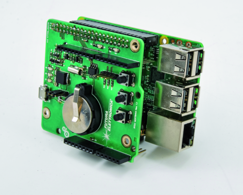
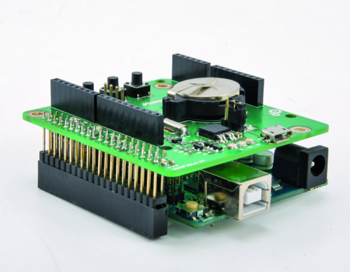
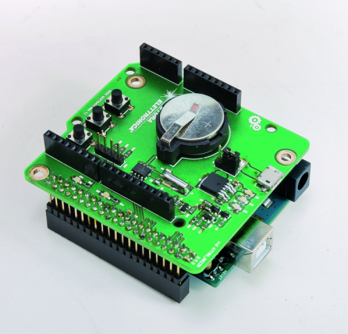
The RTCC shield has a double socketing that enables the insertion of the desired board, from time to time. After having described the firmware so to couple it to Arduino, in this last installment we will show you how to use our RTCC shield along with Raspberry Pi 2.0/B+, by taking advantage of the library that has been coded in Python and developed for this occasion. Before proceeding, we will summarize some of the details of the shield, that is based on the MCP79410 integrated circuit by Microchip; in particular, we will take a look at the interconnections between it and Raspberry Pi. Different lines are connected to the said board, among which the I2C communication bus for the management of the U1 integrated circuit (between Raspberry Pi and the U1 integrated circuit a level translator – that we better described in the first installment – has been interposed, since Raspberry Pi operates at a +3,3V voltage level, while U1 works at a level of +5V), the lines of the P1, P2 and P3 buttons, the trigger lines, the LED and the ON forcing line. If needed, the I2C bus (besides being brought to the U1 integrated circuit) may be extended – by means of the usual expansion connector – towards other boards that are connected to Raspberry Pi: the important thing is that there is no overlapping with the hardware addresses that have already been reserved. Therefore, and in summary, the following Raspberry Pi’s pins have the following use:
- the GPIOs 2 and 3 are used in order to connect the I2C bus;
- the GPIOs 17, 18 and 27 are used in order to connect the three buttons that are used by the sketch that has been coded in Python;
- the GPIOs 22 and 23 are used in order to connect the two trigger lines that are used during the debug stages;
- the GPIO 24 is used in order to manage the ON forcing line of the electronics, by means of the Q6 NPN transistor and the corresponding Q1 MOSFET, that is used as a switch;
- the GPIO 25 is used in order to drive the LD5 LED.
The description of the hardware made available by our board ends here, if you deem it appropriate to deepen your knowledge of the subject, we invite you to read the previous installment for more details.
THE LIBRARY FOR RASPBERRY PI
The library that we developed allows to configure and manage the MCP79410 in all its functions, so to make it easy to configure it for your needs, that may differ from ours.
Differently from what in the Arduino world, the library has been written in Python and is composed of two files only, having the “.py” extension.
The first one is named “MCP79410.py” and contains all the library functions, while the second one is “MCP79410_DefVar.py” and contains the declarations of all the constants and data structures. The two files are therefore part of a package that may be installed in your Raspberry Pi and used for your sketches. We will see later how the package to be distributed is generated, and how to do to install it inside of your distribution.
In addition to the two library files, we wrote a sketch, so to show how to use the implemented functions. The sketch is composed of three different files: “MCP79410_Main.py” in which the main file is found, “MCP79410_PrintFunc.py” in which all the functions for the printing to video of the data read by the MCP79410 integrated circuit are found and finally “MCP79410_SetRegisters.py”, in which all the functions for the configuration of the MCP79410 integrated circuit are memorized.
Let’s start by broadly describing the “MCP79410_DefVar.py” file that, as above said, contains all the definitions of all the used functions, in addition to the declarations of the variables and of the public and private data structures. At a first glance it is possible to see that it is an almost identical copy of the corresponding file that has been created for Arduino, with some differences that are due to the programming language that has been used.
In the beginning of the file there are the declarations of constants, such as for example the integrated circuit’s hardware addresses (we would like to point out that the MCP79410 has two different hardware addresses), or the addresses of the registers for the reading/programming of the operating parameters of the IC. A series of constants for the programming of the registers with standard values follows; this section, if associated to the careful reading of the data-sheet, helps to fully understand what to configure and how to do it, for the purpose of the correct functioning of the integrated circuit. All of the constants that have been inserted may be modified at leisure by the user, according to his needs; for each constant there is a comment, whose purpose is to help to understand the meaning of the constant.
Finally, the constants for the management of the EEPROM find place; we would like to point out that in order to access it, the hardware address to be used is different from the one of the RTCC. In addition to the constants we just described, there are the data structures that are essential for a nested management of the data for the programming/reading of the different registers found.
The data structures are divided in different sections, in particular there are: a section for the TimeKeeper, a section for the alarms and a section for the TimeStamps. Similar to Arduino, it is possible to configure the registers in two different ways: a method considers the usage of specific dedicated functions, while the other one works by means of the configuration of the data structure and following programming of the registers. For example, the following data structure enables to configure every single bit in the “CONTROL” register:
class CtrlBit(Structure):
_fields_ = [(“SquareWaveFreqOutput”, c_uint8, 2),
(“CoarseTrimEnable”, c_uint8, 1),
(“ExtOscInput”, c_uint8, 1),
(“Alarm0_Enable”, c_uint8, 1),
(“Alarm1_Enable”, c_uint8, 1),
(“SquareWaveOutputEnable”, c_uint8, 1),
(“LogicLevelOutput”, c_uint8, 1)]
class CtrlByte(Structure):
_fields_ = [(“Byte0”, c_uint8)]
class CtrlReg(Union):
_fields_ = [(“ControlBit”, CtrlBit),
(“ControlByte”, CtrlByte)]
If we suppose we want to enable the alarm 0, we will have set the “Alarm0_Enable” bit, by means of the following syntax:
MCP79410._CtrlReg.ControlBit.Alarm0_Enable = 1;
with “_CtrlReg” being the global declaration of the examined data structure, as shown by the sketch. Obviously, by acting like this we only set a value in the RAM. The next step is the one to recall a specific function in order to write a piece of data in the indicated memory location. For example, by using the “WriteSingleReg” library function, to which a series of parameters must be given, among which are the address and the value of the register whose value we wish to modify.
The complete syntax will be:
mcp79410.WriteSingleReg(RTCC_HW_ADD, CONTROL_ADD,
MCP79410._CtrlReg.ControlByte);
In addition to the data structure we just showed, other and more articulated ones follow, they allow the configuration of the TimeKeeper registers, of the alarms and the reading of the TimeStamps at the PowerUps and at the PowerDowns.
As an example, let’s see the data structure as for the management of the TimeKeeper registers, as already seen for Arduino. Please notice the difference in the formulation of the Python code (used for Raspberry Pi) in comparison to the C code used for Arduino: for each register of the TimeKeeper two data structures have been defined, followed by a “union” so to allow access to the single register, both at a byte level and at the single bit level; on the subject, you will see the first data structure highlighted in yellow, it concerns the setting of the seconds plus the oscillator’s activation bit; other data structures follow and they are highlighted in grey.
Among these sections, eight are needed just for the management of the TimeKeeper’s registers.
All of the eight sections are then grouped together in another data structure, so to have a single structured access to the registers (the section is highlighted in green). With this approach there is a single “container” from which it is possible to modify a single bit or a whole byte of the registers that are related to the TimeKeeper.
In order to better clarify the idea, we will give some examples, let’s suppose we want to set the “StartOsc” bit of the “RTCSEC” register:
MCP79410._TimeKeeper.Seconds.SecBit.StartOsc = 1
in which “_TimeKeeper” is the global declaration of the data structure being examined, as shown in the sketch.
If – on the other hand – we wanted to set the “VbatEn” bit, for the purpose of enabling the battery management of the integrated circuit, we will have to proceed as follows:
MCP79410._TimeKeeper.WeekDay.WkDayBit.Vbaten = 1
Once the registers of the above described data structure have been configured, it is possible to proceed with the actual programming of every single register of the integrated circuit, by taking advantage of the “WriteSingleReg” library function, to which three parameters must be given (hardware address, register address and value to be written in the register); or it is possible to proceed with the complete programming of all the TimeKeeper’s registers, by taking advantage of the “WriteTimeKeeping” library function, to which to give a single parameter, so to indicate if the hour management format is 12h or 24h. Therefore the syntax for programming all the registers all at once (with the 24h hour format) will be:
MCP79410.WriteTimeKeeping(0)
The functions here made available by the library are the same ones of the corresponding one for Arduino.
We will therefore avoid to describe every single function but will limit ourselves to make a list, so to focus on the code and its functions. The full list is shown in Listing 1.
We would like to point out that the “ControlByte” variable identifies the hardware address of the I2C peripheral, in this case we have two addresses: one for the RTCC and the other one for the EEPROM; the “RegAdd” variable identifies the register address that we wish to read or write, the “Bit” variable indicates which bit of the desired register we wish to modify while “RegData” indicates the 8 bit value that we wish to write in the register.
The “SetReset” and “EnableDisable” variables are respectively needed in order to set or reset a function of the integrated circuit, or to enable or disable a function.
“SetHourType” is needed in order to set the hour format (12H or 24H), “SetAmPm” is needed in order to tell if the indicated hour is before noon or after, “Alarm0_1” indicates on which alarm we wish to operate, while “Mask” is the masked comparison for the generation of an alarm trigger condition.
Finally, “PowerDownUp” indicates if we wish to read/write the registers, with the references to time and date that have been detected during the PowerUp or PowerDown stages.
Listing1
1) ToggleSingleBit(ControlByte, RegAdd, Bit)
2) SetSingleBit(ControlByte, RegAdd, Bit)
3) ResetSingleBit(ControlByte, RegAdd, Bit)
4) WriteSingleReg(ControlByte, RegAdd, RegData)
5) WriteArray(ControlByte, StartAdd, Lenght)
6) ClearReg(ControlByte, RegAdd)
7) ReadSingleReg(ControlByte, RegAdd)
8) ReadArray(ControlByte, StartAdd, Lenght)
9) GeneralPurposeOutputBit(SetReset)
10) SquareWaveOutputBit(EnableDisable)
11) Alarm1Bit(EnableDisable)
12) Alarm0Bit(EnableDisable)
13) ExternalOscillatorBit(EnableDisable)
14) CoarseTrimModeBit(EnableDisable)
15) SetOutputFrequencyBit(OutputFreq)
16) StartOscillatorBit(EnableDisable)
17) Hour12or24TimeFormatBit(SetHourType)
18) AmPmBit(SetAmPm)
19) VbatEnBit(EnableDisable)
20) AlarmHour12or24TimeFormatBit(SetHourType, Alarm0_1)
21) AlarmAmPmBit(SetAmPm, Alarm0_1)
22) AlarmIntOutputPolarityBit(SetReset, Alarm0_1)
23) AlarmMaskBit(Alarm0_1, Mask)
24) ResetAlarmIntFlagBit(Alarm0_1)
25) PowerHour12or24TimeFormatBit(SetHourType, PowerDownUp)
26) PowerAmPmBit(SetAmPm, PowerDownUp)
27) ResetPwFailBit()
28) WriteTimeKeeping(SetHourType)
29) ReadTimeKeeping()
30) WriteAlarmRegister(Alarm0_1, SetHourType)
31) ReadAlarmRegister(Alarm0_1)
32) WritePowerDownUpRegister(PowerDownUp, SetHourType)
33) ReadPowerDownUpRegister(PowerDownUp)
34) Set_EEPROM_WriteProtection(Section)
35) WriteProtected_EEPROM(RegAdd, RegData)
THE LIBRARY AS A PACKAGE
In order to facilitate the usage of the library, we created a distribution package, simply named as “package”. With such a measure the user installs the Python library that has been created on his Raspberry Pi, the latter is placed in a specific path on the disk, so to be recalled in your sketches by means of the “import” function.
In order to create a package you have to organize the code in the following way:
please create a base folder with a meaningful name. In our case it was “MCP79410”;
please create – inside of the above said folder – a new one, still having the “MCP79410” name, and inside of it please copy the two library files, “MCP79410.py” and “MCP79410_DefVar.py”.
please create an additional empty file in Python, having the “__init__.py” name; in this way the Python interpreter will see this folder as a distribution package (technically named as “package”);
in the base folder (please refer to the first step), please create the “setup.py” file, that must contain the following Python code lines:
from distutils.core import setup
setup(name = “MCP79410”,
version = “1.0”,
description = “MCP79410 Library”,
long_description = “This package is usefull
to manage the Real Time clock
Calendar MCP79410 developed
by Microchip”,
author = “Matteo Destro”,
author_email = “info@open-electronics.org”,
url = “www.open-electronics.org”,
license = “GPL”,
platform = “RaspberryPi”,
packages = [“MCP79410”])
Given that when a “setup.py” file is created, one always has to import the “setup” entry from the “distutils” library and to proceed at a later stage to compile some fields, in our case we gave a name to our distribution by means of the “name” entry, we highlighted the version by means of the “version” entry, we gave a short description by means of the “description” entry, followed by a more comprehensive description by means of the “long_description” entry. They are followed by the “author” entry and by the corresponding support e-mail address, “author_email”. The “url” entry follows, along with the link to the developer and the corresponding software “license”. Finally there is a “platform” entry, for which the code has been developed, and the “package” entry (so to identify that the one being considered is the distribution package). In order to create the distribution package the following command must be executed:
sudo python setup.py sdist
that creates a compressed file that contains the distribution package; the file that is created is “MCP79410-1,0.tar.gz”. Therefore the user that wishes to install the library will have – as a first thing – to decompress the file in a directory at leisure and then to execute the following command so to install the library:
sudo python setup.py install
In order to import and use the library in your sketches you will have to insert the following code lines in the beginning of your sketches:
import sys
sys.path.insert(0, “/usr/local/lib/python2.7/dist-packages/MCP79410”)
import MCP79410
AN EXAMPLE OF CODING
The code we just created has two different purposes: the first one is to show you how to use the available library, in addition to the procedures for the configuration of the registers of interest; the second one is the one to explain you how to interact with the hardware of our demo board, since the objective is to automatically turn on and off Raspberry Pi, under certain conditions that have been dictated by how the alarm registers have been configured.
Let’s start the explanation from the main file, that is to say, the one containing the “main()” routine.
Please notice that in the beginning of the file there are the famous code lines with the “import” instructions, so to include the library we just talked about, in addition to other system libraries that are needed.
Soon after they are followed by the declarations of the global variables, by the declarations of the constants that identify the GPIO pins that have been used and their configuration as inputs or outputs. As inputs there are only the P1, P2 and P3 buttons, to which an internal pull-up is imposed, plus an event on the falling edge, with a debouncing time of 100 milliseconds, so to intercept the pressure of the button.
We prepared two timers, so to read with the registers of our MCP79410 we are interested in, at regular intervals; one has an interval of 5 seconds (def ReadsAndPrintsRegisters():) and the other one has an interval that is equal to 1 second (def CheckAlarmsFlag():).
With an interval that is equal to 5 seconds, the TimeKeeper’s registers are read (for the purpose of showing the current date and time), as well as the the alarm registers (so to view their configuration) and, if needed, the TimeStamp registers. The latter are read only once when starting our Raspberry Pi board.
The second timer, set with an interval that is equal to 1 second, is needed in order to monitor the alarms; in the case one of the two alarms is active, one of the two following actions will be executed:
Action concerning the board’s planned switching on. Alarm 0 is set so to switch on our board’s electronics at a certain time, and consequently, Raspberry Pi as well.
Therefore, in this case the sketch will detect that alarm 0’s flag is at 1, it forces the power source to ON by means of the “FORCE_ON” line and resets the alarm flag.
Before ending the process, it disables alarm 0 and activates alarm 1.
Action concerning the board’s planned switching off. Alarm 1 has been set so to force Raspberry Pi’s switching off and therefore the one of our electronics as well, at a certain time. In this case the sketch detects that alarm 1’s flag is at logic 1 and consequently it enables alarm 0 and disables alarm 1, it resets alarm 1’s pending flag and sends the shutdown command to Raspberry Pi, which will start its switching off procedure. Once the Raspberry Pi shutdown is completed, the “FORCE_ON” line will be released, with our electronics consequently switching off.
Each one of the two timers we examined is a “thread” and in order to start them the following code line must be used:
threading.Timer(1.0, CheckAlarmsFlag).start()
in which the first parameter indicates the interval – 1 second in this case – while the second parameter indicates to which function it is associated. The first start simply occurs by recalling the “CheckAlarmsFlag()” function from the main file, before entering the infinite loop.
More in detail, we will now see the code found in the two timers: for example, the one in “CheckAlarmsFlag()”. You will notice that our MCP79410 library is recalled more than once, be it at a reading level as for the data structure only, or at a call functions level. For example, the flags of the two alarms are tested by taking advantage of the data structure:
if (MCP79410._Alarm.Alm[0].WeekDay.WkDayBit.AlarmIF == 1):
This data structure is a structure array, since the alarms are two. In the code we presented, it points to alarm 0, and in particular to the WeekDay register (ALM0WKDAY) and to the related alarm flag (ALM0IF). Please refer to the data-sheet for the details concerning the registers. In addition to the test we presented before, there are some call functions, such as, for example, “MCP79410.Alarm0Bit(0)” which is used so to reset alarm 0, or “MCP79410.ResetAlarmIntFlagBit(0)” which is used so to reset the flag for alarm 0.
Now, let’s analyze the “main()” routine: in the beginning, a reading of the EEPROM that is internal to the MCP79410 is executed (exclusively for educational purposes), and in order to do so it takes advantage of the library function used in order to read a byte array, starting from a given address. The function has three parameters:
MCP79410.ReadArray(MCP79410.EEPROM_HW_ADD, 0, 13)
The first one is the hardware address that (as already said it is different from the one of the RTCC) follows the starting address from which the data reading begins, and finally the number of bytes we want to read. The result from the reading is put into an array to which the following one points:
MCP79410.DataArray[i]
in which “i” is the array address. The maximum size is set to 16 byte. The content is then printed to video and it makes the “ElettronicaIn” writing appear. Writing in EEPROM has been carried out by means of the function with the same name:
MCP79410.WriteArray(MCP79410.EEPROM_HW_ADD, n, m)
to which to give the same parameters given to the previous one. The activation of the two timers (we talked about them before) follows, and finally there is the infinite “while” cycle.
Inside of the “while” loop the management of the three buttons, P1, P2 and P3, takes place; three different functions have been assigned to them.
The P1 button is used in order to program MCP79410’s time and date, and to do so it recalls a specific function that reads the system’s time and date and transfers them to the integrated circuit. The function that deals with MCP79410’s time and date is named “SetTimeKeeperByLocalDateTime(“24H”)” to which only a parameter must be given, that is to say, if the hour format has to be 12h or 24h. The parameter is of the string type (the function is memorized in the “MCP79410_SetRegister.py” file). If, on the other hand, you want to manually set time an date, the following function must be recalled:
ManualSetTimeKeeper(Hours, Minutes, Seconds, Set_12H_24H, Set_AM_PM, Date, Month, Year, WkDay)
which requires a series of parameters. A practical example could be the following one:
ManualSetTimeKeeper(15, 30, 00, “24H”, “AM”, 25, 12, 15, 5)
In this way the hour is set to 15:30:00 in the “24H” format, the date is Friday, 25/12/2015, and the “AM/PM” indication, has no more meaning.
Were it in the “12H” format, we would have had to give the parameters in the following way:
ManualSetTimeKeeper(03, 30, 00, “12H”, “PM”, 25, 12, 15, 5)
In both cases the functions fill the data structure concerning the TimeKeeper’s registers, and then they recall the library function that physically writes on the device.
The P2 button is used in order to program the alarms 0 and 1; for the purpose it recalls two different functions, one for alarm 0 and the other one for alarm 1.
The configuration is only of the manual kind and is only executed from the code; this means that we didn’t prepare a system to enter data from the keyboard. The function to be recalled in order to set the alarms is the following one:
ManualSetAlarm0(Index, Hours, Minutes, Seconds,
Set_12H_24H, Set_AM_PM, Date, Month, WkDay, AlarmMask, AlarmPol)
As you may notice, there are many parameters to give to it; an example could be:
ManualSetAlarm0(0, 12, 40, 00, “24H”, “AM”, 25, 12, 1, 1, “LHL”)
In this way we are telling to the function to work on the alarm 0, the hour is in the “24H” format and set to 12:40:00. The date is set to 25/12/****. The year has not been specified, since it is meaningless for the alarms. The day of the week is Monday, the mask for the alarms has been fixed at the minutes, the polarity is “Logic High Level”.
Even in this case, the function fills a data structure, and then recalls a library function that physically writes on the device. We suggest to check the data-sheet for the details concerning the registers.
The P3 button is used in order to disable and reset the alarms 0 and 1. After that the alarms have been reset and disabled, the sketch limits itself to showing the time and date read by the RTCC, with an interval of 5 seconds.
As for the printing to video of such information, the printing function contained in the “MCP79410_PrintFunc.py” file is recalled; a series of parameters must be given to it, in order to decide what to print and what not.
The function being examined is named like this:
PrintDataMCP79410(PrintTimeKeeper, PrintAlarm0, PrintAlarm1, PrintPowerDown, PrintPowerUp)
The parameters to give are just boolean values -true or false- and tell the function what to print to video.
As suggested by the names, we have the following sequence:
- printing to video of time and date;
- printing to video of Alarm 0’s settings;
- printing to video of Alarm 1’s settings;
- printing to video of the TimeStamp PowerDown values;
- printing to video of the TimeStamp PowerUp values.
If all the boolean values are set to “False”, nothing will be printed to video.
AUTOMATIC SKETCH START AFTER THE BOOT
The next step consists in making our code a self-booting one, after that the operating system’s boot has taken place. For the purpose, as a first thing we have to decide if to keep the login active or not; in the case in which we decided to skip the login stage, you have to proceed like this:
sudo nano /etc/inittab
2) search for the following line in the file:
1:2345:respawn:/sbin/getty –noclear 38400 tty1
3) comment it by using the “#” character at the beginning of the line; and add the following one (“pi” is the username) under it:
1:2345:respawn:/bin/login -f pi tty1</dev/tty1>/dev/tty1 2>&1
4) exit and save the thus modified file by pressing “ctrl+x” and after that, “y”;
5) once the file has been saved, please execute the following command:
sudo nano /etc/profile
6) go to the end of the file and add what follows:
sudo python /home/pi/PythonProject/MCP79410_Lib/WK/MCP79410_SetAndReadRegisters.py
Obviously, you will have to use your system’s path; in our case the path in which the three files of our sample sketch are found is “/home/pi/PythonProject/MCP79410_Lib/WK/”. Finally, restart the system.
CONCLUSIONS
With this, we ended the discussion concerning the management of our board, supplied with the RTCC, via Raspberry Pi. We gave some food for thought, so that you may create your diverse applications by taking advantage of our Python library, that we purposely wrote for this occasion.
All that is left is to wish you good work!
How to configure Raspberry Pi
If this is the first time that you are using Raspberry Pi or if you never tried to write some code in Python, it is appropriate to execute a series of steps in order to configure Raspberry Pi, so to use the management libraries of the GPIOs and of the I2C bus. Let’s see how to proceed, step by step:
As a first thing, please install the Python library for the management of Raspberry Pi’s I/Os and, if already installed, please update it to the last available release, that is currently 0.5.11.
- In order to verify the current GPIO library version, please execute the following command:
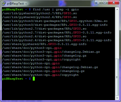
find /usr | grep -i gpio
Figurehighlights the feedback as for the sent command, in this case the library turns out to be updated to the last release. If the library release is older than the 0.5.11, please update it by using the following commands:
sudo apt-get update
sudo apt-get upgrade
or by giving the following ones:
sudo apt-get install python-rpi.gpio
sudo apt-get install python3-rpi.gpio
Let’s move on to the configuration of the I2C peripheral, that is made available by Raspberry Pi:
- let’s proceed with the installation of the “smbus” Python library for the management of the I2C bus:
sudo apt-get install python-smbus
- followed by the one for the I2C tools:
sudo apt-get install i2c-tools
We will then have to enable the I2C bus support on the part of the kernel; in order to do so it is needed to recall the configuration window, by typing in the following command:
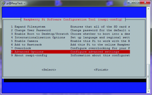
sudo raspi-config
- as in figure, let’s select the “Advanced Options” entry;
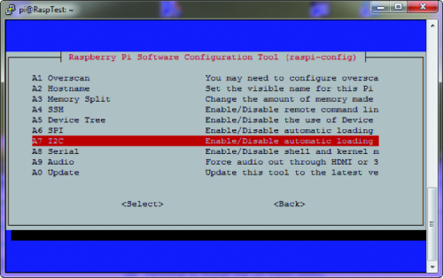
- in the new window, let’s select the “A7 I2C Enable/Disable automatic loading” entry;
- in the following screens, please answer “Yes”, “Ok”, “Yes” and finally again “Ok”;
- let’s exit from the configuration window by selecting the “Finish” entry;
Let’s proceed with a system reboot, by executing the following command:
sudo reboot
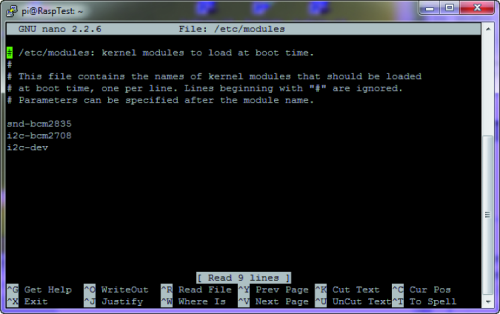
- after having restarted Raspberry Pi, please open the “modules” file by means of a a general text editor;
sudo nano /etc/modules
- please add – if they are missing – the two following lines, as highlighted by figure.
i2c-bcm2708
i2c-dev
Lastly, you will have to verify the following file in your distribution:
/etc/modprobe.d/raspi-blacklist.conf
- Should it be there, please open it by means of a text editor:
sudo nano /etc/modprobe.d/raspi-blacklist.conf
- Should they be there, please comment the following lines, by using the “#” character:
blacklist spi-bcm2708
blacklist i2c-bcm2708
At this stage, all that is left is to restart again Raspberry Pi, and to verify that the I2C communication is active. In order to do so, please execute the following command:
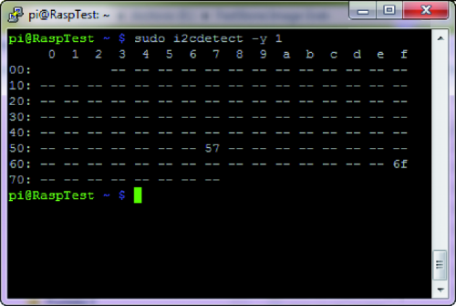
sudo i2cdetect -y 1
If everything reached a successful ending, the command sent will return a table like the one shown in figure. In practice, the command analyzes the I2C bus, looking for peripherals, and in our case it found the MCP79410 integrated circuit, along with its two addresses, 0x57 and 0x6F.


