It solves the problem of pitch loss that can trouble 3D printers and which, especially in large printers that require many hours to print parts, can mean huge losses of time and money.
In previous posts we presented a stepper motor driver, which we named MotorFish, whose special feature is to work in closed loop thanks to an in-built encoder, which allows to solve almost all the problems of loss of pitch during the operation of the motor that can affect the traditional open loop drivers, i.e those that are “limited” to send to the stepper command pulses, without verifying that the angular position of the shaft reflects them. Such a problem is also found in some particular cases on the 3D printer we created, the 3Drag. This problem is a source of problems such as misalignment of the slice of the piece in print, which is then deformed and with protuberances on the sides, so most of the time the plastic material used and the time spent are wasted.
The solution to the problem is, precisely, the motor feedback by means of an encoder applied to the motor shaft, as it happens in the MotorFish controller. In fact, the latter is a motor controller based on the Fishino architecture, but feedbacked through the signal that the encoder provides, which depends on the position assumed by the motor shaft.
PROJECT
We wanted to test our MotorFish controller “in the field”, modifying a 3Drag printer so that we could mount two drivers: one on the X-axis stepper-motor and one on the Y-axis stepper-motor. Two motors are enough because modifying the Z-axis would be superfluous, since it is practically impossible to lose steps on that and, moreover, because it has a very slow movement.
Given the limited space behind the motors in the printer, it was necessary to make some new plastic pieces that will act as mechanical adapters. Below we show you some pictures of the changes to be made and describe how to modify the drives to obtain the space needed to accommodate the motors equipped with the new MotorFish controller.
X AXIS CHANGES
The objective of the modification is to create the necessary space for the housing of the MotorFish controller behind the stepper, making a new support for it.
In fact in this modification the motor is rotated 180 degrees, in order to have the necessary space for the electronic board on the back side; so we printed the 2 elements visible in brownish color in Fig. 1, which also contribute to stiffen the fixing of the motor (before made with a single metal bracket).
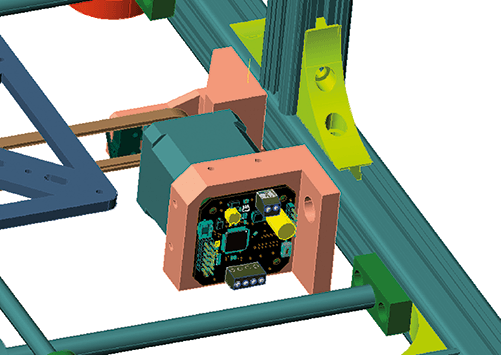
Fig. 1
In Fig. 2 you can see an exploded view of the mounting of the various elements, i.e. the stepper motor on the new mounting brackets and the MotorFish board at the back of the stepper-motor.
Note that this kind of assembly involves the “overturning” of the motor with respect to the original positioning on the 3Drag, so due to the overturning to which the stepper will be subjected in this variant of assembly, in the firmware settings it is necessary to select the counterclockwise rotation of the motor ( point 3 of the main menu of the MotorFish software). The positioning of the encoder should instead be left in standard mode, or on the back of the motor (point 2 of the menu). Note that the menu items refer to the MotorFish management menu, which is able to present a user interface for configuration when connecting to it via the communication port using a PC and a terminal emulator.
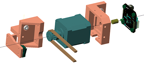
Fig. 2
Y AXIS CHANGES
Here things get complicated, due to the lack of space on board the 3Drag, which is designed to support normal NEMA17 pass-through motors. For the modification we propose here two possibilities, recommending the second variant. In our case we have in fact started with the first version, which lasted more than a year, but then began to show signs of fatigue due to vibrations of the element used to extend the shaft of the motor.
First solution
So let’s see the first solution, proposed in Fig. 3: as you can see in the picture, the support for one of the bars of the Y-axis is replaced with the element in brownish color; the motor maintains practically the same position of the traditional version of the 3Drag. As you can see, the board is fixed to the new support and the movement of the encoder magnet is made through a plastic extension, also 3D printed, inserted in a bearing, as shown in Fig. 4.
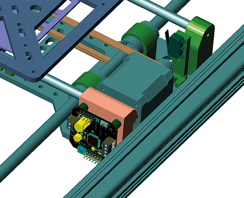
Fig. 3
This modification would be ideal if it were not for the precision needed (practically unachievable with home-made means!) to correctly make the small shaft-extension that you see in the above picture: in fact even a minimal misalignment is enough to make it vibrate and, in the long run, to make inaccurate or even break the connection with the motor.

Fig. 4
As we explained earlier, in our case this happened after more than a year of flawless operation, so in a way that would have been difficult to predict.
With this change, in the firmware settings you need to select the RETRO MOTOR positioning for the encoder (menu point 2) and the CLOCKWISE MOTOR rotation (menu point 3).
Second solution
Let’s now look at the second solution, which may seem a bit more laborious initially, but is more reliable in the long run; you can see it proposed in the rendering in Fig. 5.
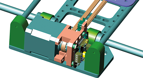
Fig. 5
In this case, a front support is made for the MotorFish, moving at the same time the small limit switch microswitch; the magnet is glued directly to the front pin of the engine, as it appears in the exploded view you see in Fig. 6 where it is represented by the green cylinder.

Fig. 6
The modification is not complicated in itself (you need to print three support elements plus four small spacers) but the insertion of the assembled complex in the mechanics of the 3Drag printer is quite difficult, due to the limited space available.
In this case it is necessary, in the firmware settings, to select the frontal positioning of the encoder, at point 2 of the menu, while the rotation of the motor should be left clockwise (point 3 of the menu).
CONNECTIONS TO THE CONTROLLER
Once the mechanical assembly of the two drivers has been completed, it is necessary to make the connections of the Motorfish with the main board.
First of all, it is necessary to remove the two drivers relating to the X and Y axes from the controller, because they are no longer needed, since the Motorfish will drive the windings of the relative stepper-motors. Below we indicate them both for the “standard” version of the 3Drag (board supporting a single extruder) shown in Fig. 7, and for the “dual” version (board supporting the double extruder) shown in Fig. 8.
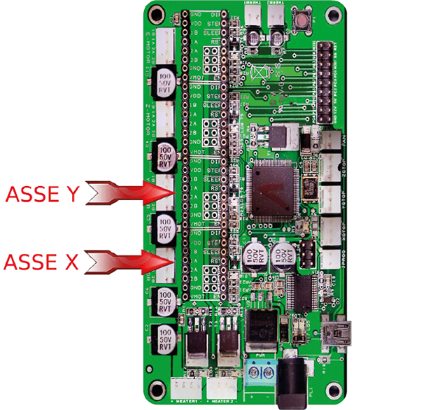
Fig. 7
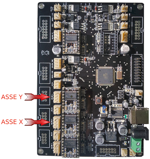
Fig. 8
Once the two original drivers have been removed, it is necessary to make the connections between their sockets and the pads of each Motorfish board; in practice it is necessary to connect the lines indicated in Fig. 9 of each of the MotorFish to the contacts of the sockets on the controller board which correspond to the pins of the drivers shown on the right in the same figure by the red arrows.

Fig. 9
For a correct connection, remember that the MotorFish board is seen from the bottom side and has been shown like this because the writings are on that side; the connections must instead be made on the upper side where the connection header is located.
For the connections you can use very thin unipolar wires (even AWG32) except for the VM voltage and GND, where we suggest to use wires able to withstand a current of a couple of amperes. Theoretically the current would be lower (we are talking about 1 ampere or so…) but it is better to avoid the high inductance caused by too thin wires. So use two AWG18-20 or, at most, 22 wires, for VM and ground; translated into square mm cross section, something like 0.75 square mm is fine.
FIRMWARE CONFIGURATION
For the configuration of the firmware that runs in the MotorFish, we refer you to the article in which we described the card, or to the booklet no. 236, where we have outlined the software aspects; here we limit ourselves to remembering that to interact with the firmware and proceed with the appropriate settings it is sufficient to use a serial connection with the MotorFish and start the Arduino serial monitor, on which the configuration menu will appear. This is because, as mentioned, the board is based on Arduino architecture and as such can interface with the IDE and the Serial Monitor.
CONNECTING THE DRIVER FOR FIRMWARE CONFIGURATION
The driver can be programmed and tested directly while it is mounted on the 3Drag; obviously if you make some gross mistakes the printer moves and you risk doing damage, even if they are almost always not “serious”.
The only more serious problem we’ve had is leaving the USB cable connected to the MotorFish during testing, misdirecting the motor when programming the firmware, and seeing the printer plate cut cleanly through the USB connector on the board.
In that case, since the tracks usually come off together with the connector itself there is little to do but throw it all away and buy a new MotorFish, so… be careful!
To overcome this problem we suggest to put some mechanical block to prevent the plate from reaching the lower end during the tests (for example a metal or wooden bracket) or, if you prefer, use the alternative serial port of the MotorFish by modifying the following line:
#define MOTORFISH_SERIAL Serial
to turn it into this:
#define MOTORFISH_SERIAL Serial0
The additional serial port is accessible on the SDI / RX (RX) and SDO / TX (TX) pins; obviously it is necessary to have a USB / SERIAL converter available to use it.
With this system it is possible to configure the firmware without the use of a USB connector connected to the board during operation.
DETERMINING THE MAXIMUM SPEED OF THE STEPPER MOTORS
The MotorFish firmware also contains an experimental “maximum speed measurement” mode for use with motors mounted on the printer. This runs a full revolution of the motor at the maximum speed it can impart to the mechanics and measures it.
Do not consider this measurement a usable value, but only a “limit” value; we suggest you experiment with half the speed detected by the driver, and set it in the Marlin parameters. You can also experiment with acceleration and other parameters, but you need to understand how the system works. In the old drivers, too high a speed or acceleration caused the loss of steps and therefore cumulative errors in the print; in short, the object printed too fast would accumulate errors until it became unrecognizable in a short time.
With our drivers, steps are not lost or, better said, lost steps are recovered as soon as possible. This means that if you set your software speed and/or acceleration too high, the printed objects will still be recognizable and, at a certain distance, they will always look perfect. On closer inspection, however, you will see the loss of detail and everything that results from local errors.
On the website www.fishino.it you will find all the details of the modification and the drawings of the elements both in dwg format (that of Autocad) and in the form of .stl files to be used for 3D printing; indeed, precisely due to the fact that the application of the MotorFish board proposed here was born precisely for our 3D printers and assuming that if you make it it means that you have a 3Drag printer, starting from the .stl files you will print the additional plastic parts needed to perform the modifications and once the pieces have been printed, you can assemble them as explained in these pages.
CONCLUSIONS
Once the change has been made, before launching the print, you must reconfigure the Marlin software to set the correct number of steps per mm on the X and Y axes, otherwise you risk finding the parts “scaled” in the horizontal directions.
MotorFish provides a microstepping of 64 microsteps / step, which in the 3Drag correspond to about 257 step / mm; this is the number to be entered in the Marlin firmware configuration screen for the X and Y axes. Once the software has been set up, you can try to launch a print, manually lock the printer plate with one hand, release it after a while, and you will see that the printer will recover its correct position limiting the error to the short time in which the plate has been blocked. You can also experience higher speeds and accelerations than the standard ones (pay attention to the mechanics, the writer has managed to “unscrew” the bolts of the plate support by exaggerating the acceleration!). This concludes the series of articles related to our MotorFish driver, at least for the moment. The possibilities of using the driver are, in fact, countless and it is not excluded that we will present others in the future.
FROM OPEN STORE
Controller with feedback for stepper motor
Bipolar stepper motor NEMA 17 – 1,5 A

Good read. Nice information and very detailed.