
To create a PCB with 3Drag , by milling , it is necessary to have the G-Code files for the tracks patterning and for the holes relating to the printed circuit board itself. In this section we describe how to obtain these G-Code files using a specific plugin for the popular PCB design software ” EAGLE “.
Note: This operation can be done only if the PCB you want was created with EAGLE .
The PCB- gcode plugin allows to create the G-code files for patterning the top copper tracks, bottom copper and also that relating to the drilling of the base created with the freeware program EAGLE . It also allows to define the extension of the file that must be exported ( .nc) so that it is compatible with Repetier -Host.
In succession we described here the procedure to create a simple single-sided PCB by milling incision.
– The first operation is to download the software EAGLE from CadSoft download by choosing the version for your operating system.
– Carry out EAGLE freeware installation launching the .exe file
– Download the PCB – gcode (version taken into consideration: 3.6.0.4 ) from this web site (you must have a YAHOO account) or download from the dedicated forums .
– Unzip the folder and then copy the files in the ULP folder of EAGLE.
– Start EAGLE, click on File/Open/Board and select the file of the PCB that you want to create by milling .

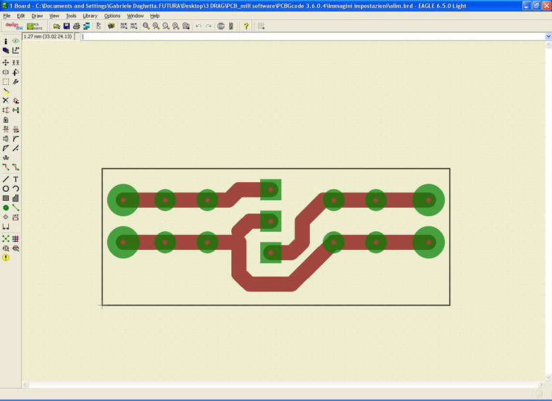
Mirror the printed circuit board and align the lower left corner of the base with the starting point of the worksheet . This operation is to keep the PCB in the work plan and to orient the PCB so that the copper side to work (called “Bottom Copper” ) is facing upwards.
Note: It is recommended to set a unique value for the central hole of all the plots in order to use a single drill bit .
PCB- gcode parameters configuration
– Start PCB- gcode typing this command in the command line: run pcb- gcode -setup

After sending it you will see the following window in which you have several configuration folders (Generation Options , Machine, GCode Style, GCode options ….) :

In the “Generation Options” folder check the two entries under “Top Side” and the entry Single pass of “Isolation” . This allows to make tracks patterning with a single pass of the tool.
Set a value for the minimum insulation (Minimum ) and the size of the milling tool bit used (Etching Tool Size) , for example 0.2 mm .
Note: the unit “mm ” must be set in the “Machine” sheet.
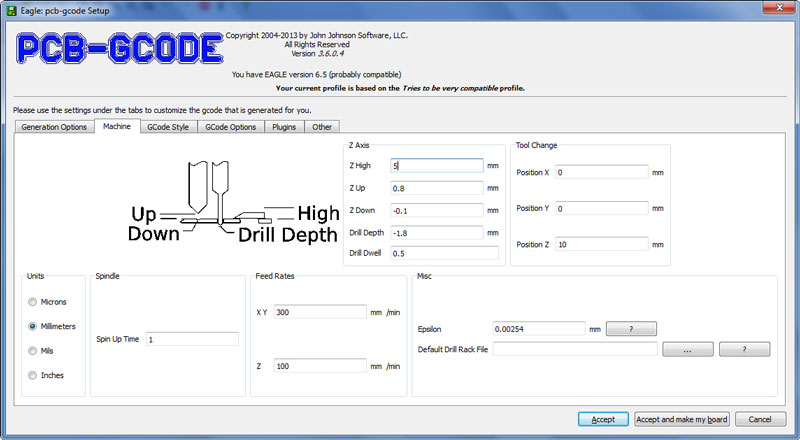
In the “Machine” folder you have to set, in addition to the unit of measurement (mm , Mils , etc …), the parameters related to the machine advancement or the ” Feed Rates” (300 mm / min for X and Y and 100 mm / min for Z ) , positioning of the Z …
Z High: maximum lifting of Z (e.g. 5 mm);
Z Up: lifting of the Z while moving from one point to another (e.g. 0.8 mm);
Z Down: incision depth (e.g. 0.1 mm) ;
Drill Depth (e.g. 1.8 mm, depending on the base thickness);
Drill Dwell: waiting time before the rise of the drill bit (e.g. 0.5 s)
The position for the tool change (no bit change is done) and other parameters not taken into account for the PCB construction.
Note: the complete manual of PCB- gcode (pcbgcode.pdf) is available under the “docs” folder of the pcb- gcode – 3.6.0.4 program downloaded.
In the folder ” GCode Style ” you can set the generated G -code style more suited to your machine (we chose C :/ Program Files (x86) / EAGLE-6.5.0/ulp/profiles/generic.pp ) .

The folder ” GCode Options” allows to choose whether to insert comments in the generated G -code (in our case do not check any item) , if use a custom G -code and more. In the creation of our PCB we just ticked off the entry ” Use simple drill code” (which allows to get a drilling G -code compatible with Repetier – Host) and called ” nc” as Extension ( always to make the generated files compatible with Repetier – Host) . The last 2 folders (Plugins and Other) were not taken into account.

After setting PCB- gcode parameters, click Accept to confirm your choices ( the setup window will close and on the monitor the Board Editor screen with its own PCB will reappear.
To create the G -code files useful for tracks etching and base drilling , type in the appropriate field run pcb- gcode and press enter.
Repetier-Host settings and G-Code import/modifications
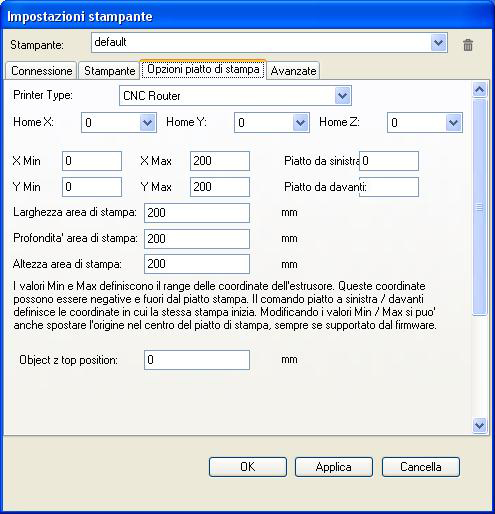
Open Repetier Host, select “CNC Router ” (from ” Printer Settings ” in the upper right , indicated by the red arrow )
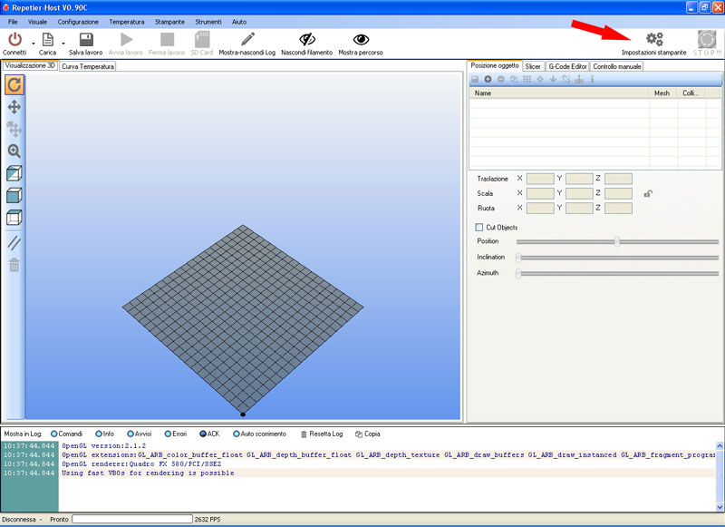
and set the parameters as follows:
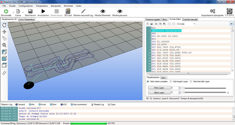
Load in Repetier -host the Gcode xxx.top.etch.nc or the file for the tool route of the PCB you want to realize (xxx is the name assigned to the PCB , in this case “alim”).

In the 3D window will appear the outlines of the PCB tracks that will be made by milling (Show Filament and Show route must be operative) .
From G -Code Editor delete the initial lines in which there are round brackets (in this case only the second command line) .
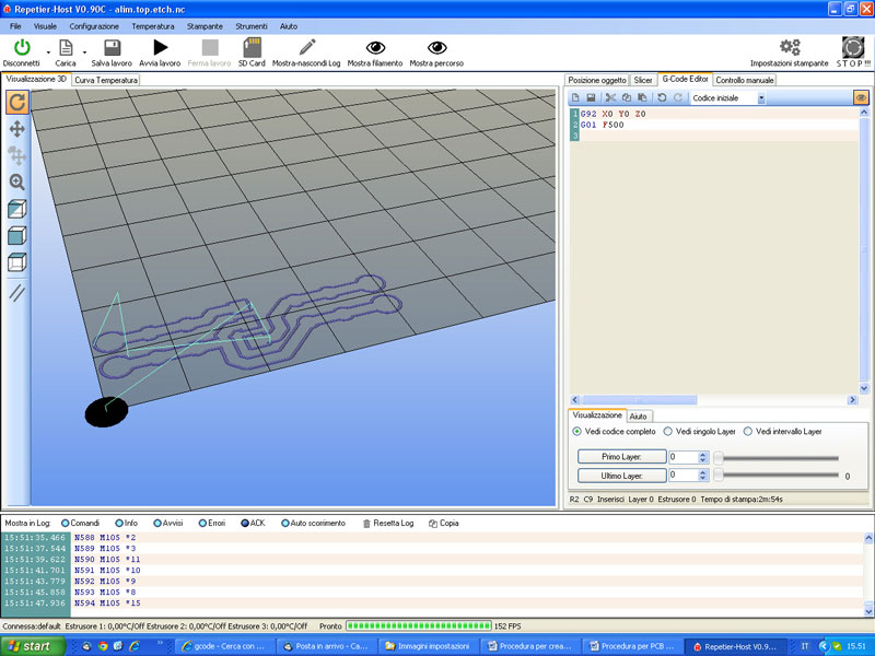
Click on the dropdown menu of G -Code Editor and select “initial code” .
Enter the initial GCode shown in the picture below
G92 X0 Y0 Z0 ; offset of the coordinate system , set X0 Y0 Z0 as a starting point ;
G01 F500 ;linear movement with speed of 500 mm / min
then click the disk icon to save it.
Now select ” Final G-code ” ,enter
G01 X0 Y0 F500; back to X0 Y0 position with linear movement of 500 mm / min
and save it.
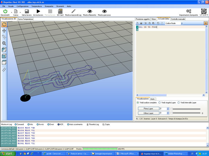
These changes are needed to define the offset of the coordinate system so that the machine operates in the desired area and back to the starting point when processing is finished.
Preparation of CNC machine
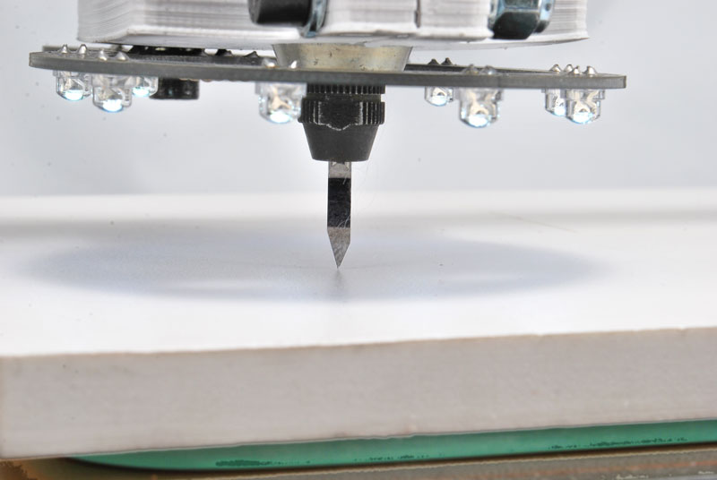
Insert and lock in the electric mandrel pliers the milling burin, whose bit size must be the same of that defined in the settings of PCB- gcode (hard metal burin is recommended as the fiberglass is highly abrasive!), and let it stick out as less as possible, in order to avoid vibrations and an excessive run out .

Pull the tool as close as possible to the sacrificial plane so as to touch it. Move the plane in all directions to make sure that the distance from the tool is constant. Perform a pre- adjustment of the printer plate, by acting on the knobs , so that it is as much as possible coplanar with the tool.
Attach the strip copper to work on the sacrificial level, with the double-sided tape.

After attaching the base with double-sided tape is necessary to make a fine adjustment by acting on the knobs , so that the base is coplanar with the tool. To perform the procedure you can, as we did before, approach the tool bit to the base and then slowly move the plate in the X and Y direction so that the distance remains as constant possible over the entire surface of the base; you can also use an indicator – with the adapter that we previously printed – inserted into the collar provided for the electric mandrel and as shown in the following pictures:

Start milling tracks pattern
Lower the Z-axis (using the Repetier-Host manual control) just enough to pull the chisel close to the base (about 2-3 mm) and then adjust the X and Y axes to position the tool at the origin of the PCB that you want to mill. Now, turn on the electric mandrel, set the maximum speed then manually rotate (very slowly) the Z motor shaft to lower the machine arm until it touches the PCB with the burin bit. The correct zero is obtained when the tool starts to “polish” the underlying copper without milling it .
Now press the ” Start Work” button of Repetier – Host and the machine will perform the patterning of the PCB as programmed. As the incision will be completed the power tool will be bring back to the starting point. It is recommended not to change this position in order to avoid a misalignment of the holes that will be made later!
Turn off the electric mandrel.
Start drilling
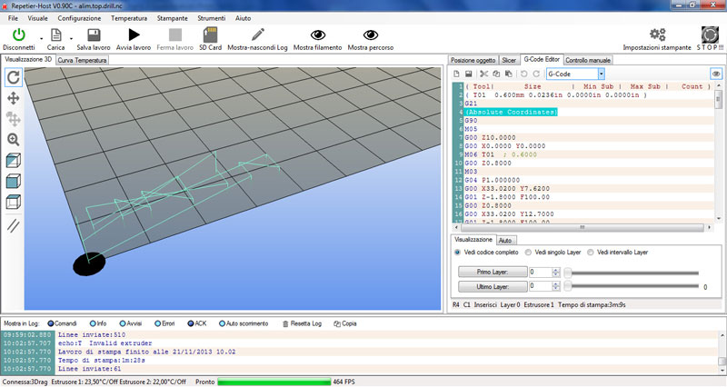
Load in Repetier the Gcode xxx.top.drill.nc or the file relative to the drilling plane of the PCB just engreved (previously created with PCB- gcode ) , in our case ” alim.top.drill”.

The routes of the drilling tool will appear in the 3D window (Filament Show and Show route must be operative) .
From G -Code Editor delete the initial lines in which there are round brackets (in this case the first, second and fourth command lines) .

Pick up few inches the Z-axis by acting on the manual control keys (be careful not to move X and Y!) and replace the burin with a drilling bit of suitable diameter (e.g. 0.8 mm).
After tightening the mandrel, pull down again the Z-axis to position the bit at about 1-2 mm from the copper plate. Now, turn on the electric mandrel and rotate manually (very slowly) the Z motor shaft lowering the machine arm until it touches the PCB with the bit. The contact point should coincide with the contact point previously defined with the milling tool.
Note: It is recommended to do this manually so as not to break the bit due to a maybe incorrect advance selection made in the manual control panel of Repetier -Host.
Now press ” Start Work” of Repetier – Host and the machine will run the drill expected for PCB after which will reposition itself in the coordinates X0 Y0 .
Turn off the electric mandrel.
The PCB has been realized by the machine exactly as per EAGLE project!

[…] To create a PCB with 3Drag , by milling , it is necessary to have the G-Code files for the tracks patterning and for the holes relating to the printed circuit board itself. […]
[…] Creating G-Code via EAGLE software – [Link] […]
[…] looked for some EAGLE scripts that will output already useful G-code and was successful with PCB-GCODE. Some modifications were to do, but i was able to output G-code that switches the fan output […]
Hello,
First of all thank you for a so well written article.
I followed your instructions and i was able to export the gcode file and load it into repetier software. The only problem is that the pcb my cnc drew is about two times smaller than the pcb in eagle. Any ideeas?
Thank you!