
Designed for small amplified audio speakers or as output stage for MP3 players, radio receivers or compact hi-fi systems; it is based on a class D integrated circuit which, thanks to the high efficiency, is ideal for battery-powered solutions.
Small power amplifiers for battery-powered audio devices must satisfy two requisites, which are essentially low consumption and reduced thermal dissipation; the two things are, in a sense, opposite faces of the same coin, because low heat dissipation means that output power being equal, the circuit loses small amount of power in its final stage. When power is taken from a battery it is crucial to save energy as possible, in order to obtain higher autonomy. The project we propose in these article was designed in order to offer a device requiring the lowest possible current, output power being equal; in fact, it is a class D amplifier, which is different from class AB (and even more different from class A) due to its really high efficiency, which can go up to 90% or higher (compared to 60% of class AB). This means that in order to provide the maximum 2.8 W to the speaker, this circuit needs a power of just 3.1 W. In order to obtain such characteristics we chose to take advantage of an integrated SSM2305 by Analog Devices, which is a complete filter-less SMD class D stereo amplifier, so it doesn’t require an L-C output filter; actually, as you will see in the circuit diagram that we are going to analyze shortly, there was a filter, but the term filter-less is generally used to indicate class D amplifiers that do not require tuned circuits and big-sized coils since they work at really high frequency.

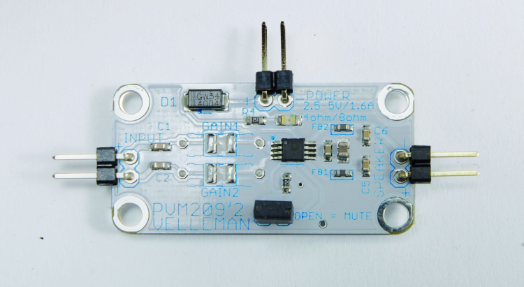
Using an integrated SSM2305 allows us to omit a heat radiator therefore reducing the size (the printed circuit measures just 20 x 40 x 10 mm) and it also allows us to insert the circuit in containers without airflow, since we have very little heat to dissipate.
Class D
Before moving into analyzing the real circuit we would like to take some time to explain what class D is and how such an amplifier works: the amplifier’s hearth is the PWM modulator and it is necessary because class D is based on the modulation of impulses’ width, meaning that the audio signal is converted into impulses of equal amplitude, and their width is directly proportional to the amplitude of the input signal. Class D configuration is used in order to increase efficiency when it is necessary to keep dimensions, consume and dissipate heat on the low side. The PWM amplifier typically works like this: the audio signal is introduced on the non-inverting input of a voltage comparator, while on its inverting input a triangular shaped voltage of the same amplitude but with a frequency 10 times higher is applied (but it can also be much higher); on the comparator’s output there is high level voltage when the audio signal exceeds the triangular wave and a low level in the opposite case, therefore a series of impulses with constant amplitude and frequency, but with varying period duration which grows proportionally to the audio amplitude (with the same frequency of the triangular wave). By amplifying the impulses’ power through a transistor stage and by filtering them with an L/C low-pass filter, we rebuild the input audio signal. The class D amplifier is an example of how we can treat an analog signal by using impulses that can only assume two voltage levels and which allows us to obtain a really high efficiency because the transistors powering the load do not work in linear zone but on an impulse base, switching on and off (they behave as static switches); in fact, by using MOSFETs, which have an on-state resistance of a few milliohms, we can limit the power consumed in the final stage reducing it to negligible amounts. Despite powering the speaker by impulses and therefore with digital signals, the amplifier is still analogic because impulses’ width and therefore the mean value of the voltage applied to the speaker is linearly proportional to the amplitude of the input signal.
Circuit diagram
Let’s take a look now at the amplifier’s circuit, which is basically contained in the integrated SSM2305; this is a complete class D mono amplifier designed for mobile applications that contains a differential input buffer (which inputs refer to 3-pin and 4-pin, non-inverting and inverting inputs respectively) and a PWM modulator that receives a triangular reference signal for the comparator. A dedicated processor implements a distributed spectrum modulation to reduce output interferences. The rectangular signal obtained by the modulator drives a bridged MOSFET stage with complementary symmetry (which means it is composed by two transistors turning on alternatively), providing current to the speaker and without reference to ground, it has in fact to be connected to 5-pin and 8-pin.
The oscillator from which we take the triangular wave for the modulator works at fixed frequency that is set to 280 kHz by the internal components of the integrated circuit, more than enough to cover the audio frequency.

The IC requires very few external components, which are essentially a couple of capacitors for decoupling inputs, two resistors to limit amplification of the input stages and a couple of inductors and as many capacitors on the outputs. The resistors connected in series to the inputs are used to set the amplifier’s voltage gain and represent the inputs resistances of amplifier stages in inverting configuration, because retro-action of each channel of the IC1 follows; the internal retro-action resistance (Rf) is fixed and equal to 296 Khom, we can act on the gain (given by the Rf/Ri ratio, where Ri is the resistance connected in series to the considered input) and by choosing an adequate value for R1 and R2. Actually, the IC already has a connected network inside with values for Rf and Ri set respectively at 296 and 37 kohm, and this sets the voltage gain to 18 dB if there are no resistors connected in series to the inputs; 18 dB is a bit less than nine times, this means that in order to obtain maximum output power on 4 ohm each channel must receive a voltage input of 350 mVeff.

Preset gain can be reduced by inserting resistances, which are R1 and R2 in our diagram, both can be bypassed using bridges SJ2 and SJ2; by inserting the resistances (and therefore opening the pictures) the gain is reduced to:
G = 296k/(37k + R)
Where R is the value of R1 or R2.
We must remember that the output resistance of the source for the audio signal that we want to amplify affects the gain, because it is connected in series to the inputs, therefore the exact amplification also depends on that.
Now, let’s move on to the output; we can see that each one is filtered by a L/C cell composed of an inductor for EMI filtering (Electro Magnetic Interference) which is connected in series to it and a capacitor connected in parallel to the speaker, which purpose is to (almost) suppress impulses, by presenting a voltage which has the same waveform of the input but is of course amplified. Inductors are made by Murata following 0603 format per SMD and their impedance is 120 ohm at 100 MHz with a direct current resistance of just 50 milliohms.
Final elements for the circuit are the inversion-protection diode (D1) connected in series with the positive power terminal and the filter capacitors for power itself (C3 and C4), besides LD1 LED, which lights on to indicate power (R4 limits its absorption). Finally, note the P1 bridge that allows us to put the amplifier in standby; in fact, when /SD pin is left on logic zero (thanks to the pull-up resistor R3) the IC shuts down, therefore stopping the oscillator and the PWM modulator, besides turning off the power stage. This way the amplifier consumes just 30 milliamps. You can swap the jumper with a logic circuit to maintain the /SD line to zero when the amplifier must be turned off and to bring it to logic 1 when the amplifier must be turned on. This control is ideal for on/off switching with an integrated MP3 player or similar.
From openstore
Class D audio amplifer – mono 2.8 W
