- Building a 3D Digital Clock with ArduinoPosted 4 months ago
- Creating a controller for Minecraft with realistic body movements using ArduinoPosted 5 months ago
- Snowflake with ArduinoPosted 5 months ago
- Holographic Christmas TreePosted 5 months ago
- Segstick: Build Your Own Self-Balancing Vehicle in Just 2 Days with ArduinoPosted 6 months ago
- ZSWatch: An Open-Source Smartwatch Project Based on the Zephyr Operating SystemPosted 7 months ago
- What is IoT and which devices to usePosted 7 months ago
- Maker Faire Rome Unveils Thrilling “Padel Smash Future” Pavilion for Sports EnthusiastsPosted 7 months ago
- Make your curtains smartPosted 8 months ago
- Configuring an ESP8266 for Battery PowerPosted 8 months ago
RandA: WebServer application

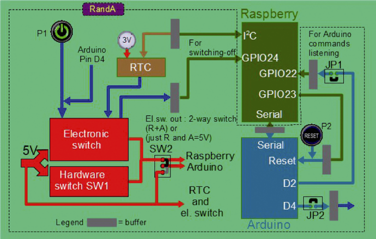
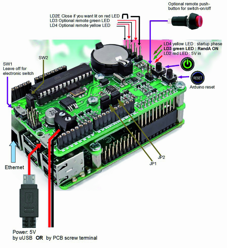
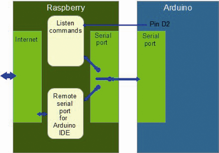
In case you missed our previous articles, we summarize briefly what is RandA. RandA is a system that allows a physical and functional integration between Raspberry Pi and Arduino, allowing the use of Arduino shields with the Raspberry Pi computational power. It also includes an intelligent power management and a RT clock. In figure shows RandA functional diagram, while in the second figure shows the structure and connections.
Let’s start with order. Assuming you do not have the SD Memory Card already configured (you can purchase it from us), the first thing to do is to install the necessary software to have RandA working. In fact, without it, the hardware electronic switch, the RTC clock and Arduino itself could not work with Raspberry Pi. In addition, the software includes a plugin to be installed on your PC to set Arduino’s IDE to use the remote port and upload software to RandA connected to a LAN. You have to install this part even if you have the board configured already.
In this case the installation files archive can be found in / home / pi / RandA.
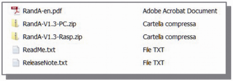
The software can be downloaded from our website along with the project file. It is a compressed archive (zip) that contains two files: one for your PC and one for the Raspberry Pi on which is mounted RandA. It also contains an English manual.
The procedure to follow to install software is the following:
- Unzip the “for PC” archive and extract from this the files to be put into the “lib” folder in Arduino IDE (use only version 1.0.5). Before that, for safety, rename the three files you’re going to replace. The IDE will be modified by the previous steps. To end up, just extract the RAComm library and put into “libraries” folder
- Extract the “RandAinstall.tar.gz” archive and file “RandAinstall.sh” from Raspberry Pi archive
At this point, we have to work on Raspberry Pi. Since the Raspbian installations (remember that the software is designed for this operating environment) are configured with the SSH server already running, we can connect to Raspberry Pi via LAN through a software supporting this protocol. We assume that you use MobaXterm, which also contains an X window server and a comfortable FTP GUI in addition to the Linux console.
So, identified the Arduino LAN address (we can identify it through the router or through utilities that do the scanning of the network as “Advanced IP Scanner”), we open an SSH session with it (Fig. 3). We immediately see that there is a FTP window beside the console. At this point we just have to upload to Raspberry Pi the two files. We can put them in folder / home / pi. Before starting the script RandAinstall.sh you have to set it “executable” using the command:
“sudo chmod 777 RandAinstall.sh”
Now all that remains is to run the script using the command (assuming you are in / home / pi):
“./RandAinstall.sh”
and you’re done!
Remember that, since the script installs Arduino IDE for Linux and “Codeblocks” from Raspbian website, you must have a working Internet connection.

If you had not an Internet connection available, you can install “Codeblocks” and Arduino IDE later on, using the commands:
sudo get-apt install codeblock
sudo get-apt install arduino
After the IDE installation you must manually customize the IDE on Raspberry Pi, referring to the three lines that you find on installation script in the Arduino IDE editing section.
Test
Let’s test now if RandA is operating and to become familiar with this system.
First, we restart the board to make the software working, using the command:
“sudo reboot”
The system turns off (the SSH session is closed) and then restarts. Now you should see the yellow LED off after a while. The yellow LED, in fact, is on for the duration of the startup and its switching off means that the system is ready to operate.
We open again the SSH session and we should see the new welcome message with the list of RandA specific commands. Doing the “refresh” of the sftp box (right mouse button), we will also see the new directories created in / home / pi.
We can try the cooperation Raspberry-Arduino using a breadboard as in figures.
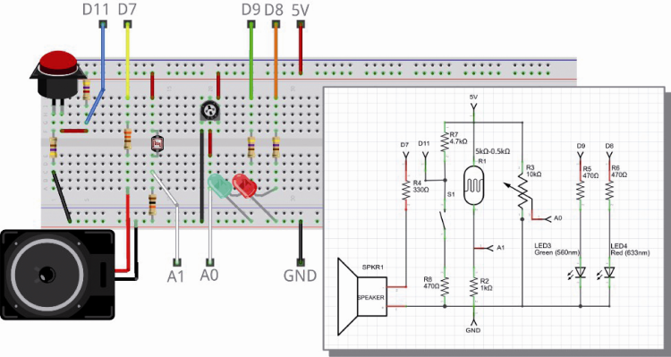
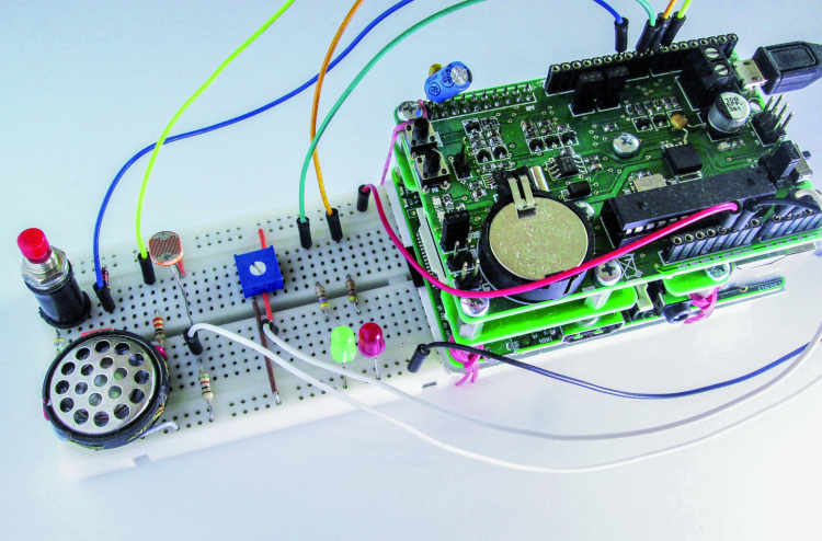
Type “ArduIO -h” to show the help. Now we can try to switch the RED Led on with the following commands:
- ArduIO -set 8 out
- ArduIO -wrd 8 1
If you do not have the breadboard shown, you can still test the Arduino I/O by using the standard LED (pin 13). Therefore, you have to do:
Arduio -set 13 out
and
Arduio -wrd 13 1
Arduio uses the SerialRasp sketch. If none is found on Arduino, it installs it but in this case, it must be launched again. The sketch used is also available as “sourcecode” in the sub-folder “schetch4cmd” to “/ home / pi / bin”.
To switch it off, type:
ArduIO -wrd 8 0
In the same way we can trigger the green Led (pin 9). But we could operate it with the PWM to have a variable light intensity (only the 9 pin).The command is, to have 50/255=1/5 of the intensity:
ArduIO -wra 9 50
We read the value of the photoresistor on A1 (or the voltage divider on A0) using the command:
ArduIO -rda 1
We send a 600 Hz square wave on D7:
ArduIO -pou 7 600
To stop it :
ArduIO -puo 7 0
Of course the sound power is low, because of direct driving from Arduino. If we want a more powerful sound we must use a buffer or a connection to an amplifier.
Finally we can read the duration of a pulse (from the value 1 to the value 0) on D11:
ArduIO -pin 11 0
If we were to measure the duration of the value 0, we would have to write:
ArduIO -pui 11 1
If you use the button, remember that the timeout is one second. Finally, we can use the button as digital input:
ArduIO -rdd 11
Actually, you could communicate with Arduino using the serial port directly:
echo “WD13=1” > /dev/ttyS0
This command turns the Arduino LED on (pin 13), if the “SerialRasp” sketch is loaded on Arduino (the one used by the command ArduIO); in fact it corresponds to what the command “Arduio -wrd 13 1” does. The protocol used by SerialRasp is very simple and is described in the sketch source code.
Web Server
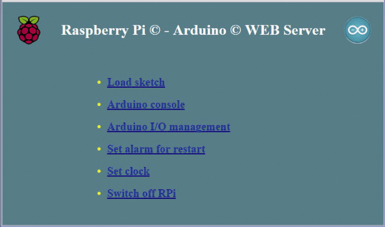
Now let us try the browser access. If you work in LAN, enter the RandA numeric IP address in your favorite browser, and you will see the server start page. If you just turned RandA on, please have a little patience before accessing the address; wait about ten seconds after the yellow startup led switched off, to let the web server to initialize properly. Click on “RPI & Arduino management” and you will see the main menu.
We can try to use the same breadboard to test the communication via eeb. Then click on “Arduino IO management” and we will see the screen.
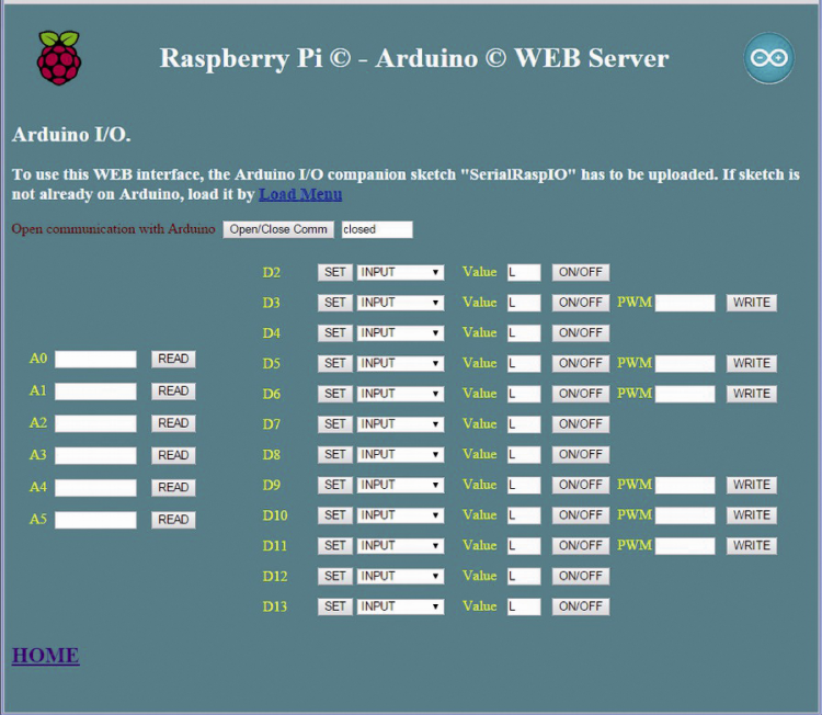
If you have tested the breadboard with ArduIO controls already , you have uploaded the sketch used to manage the pin, which is basically the same that is used by this application. Otherwise, you must first load it by using the “Load sketch” page.
In this screen, the first thing to do is to open the serial port communication (wait until “open” is displayed). Then you can use the various buttons to configure, change or read values. For example, to read the illumination value from the photoresistor, click on <READ> at A1.
Let’s go back to the menu and move to the “Load sketch” page in figure. You can see that there are two main panes, one with a list of sketches and one that contains the description that you can type or edit directly. Actually the lists are two, switchable via the selection of the scrolling list. One folder contains sketches the created with the remote IDE and the other those created with the local IDE (on Raspberry Pi).
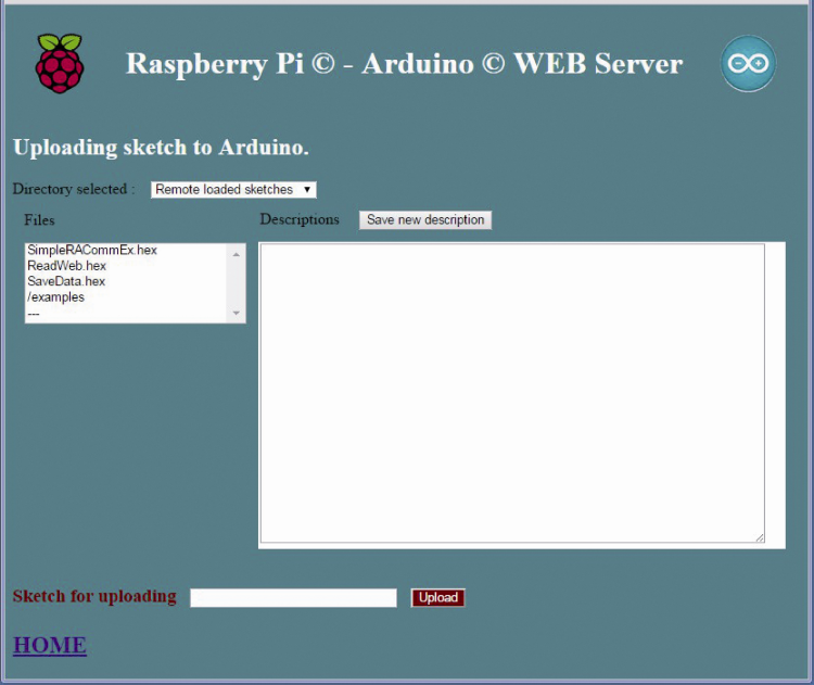
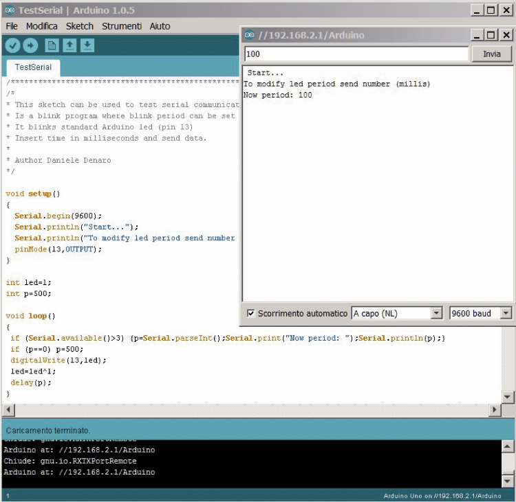
We select the sketch “TestSerial.hex” inside the folder “/ examples”. Now we click on <Upload>. You should see the message “uploading successfully performed” (if he had some problems, do a reset or make again an upload). At this point you just have to use it. Let’s go back to the menu and select the “Arduino console”.

First we check that the selected speed is 9600 baud and then we open the serial port. We wait until it is “open” and click on the button <Arduino Reset> to restart the sketch. Now we can change the blinking time by entering a value in milliseconds (> 100) in “Send data” and pressing enter. Remember to close the serial when you leave the page. Then we could go to “Set clock” and enter the correct clock value. We can automatically take it from the system one. In fact if Raspberry Pi is connected to the Internet, it should have the date updated. Then we could use the page “Set alarm for restart” to set a time for automatic restart, and then turn off RandA via the “Switch off RPI” which launches a shutdown and then cuts the power off.
RandA as a strengthened Arduino
Supposed you also bought the already configured SD card, then the installation is reduced only to customize the Arduino IDE you already use on your PC. This operation was described at the beginning of the article. The installation archive is present, as a backup, in / home / pi / RandA. You just have to copy the archive on the PC, for example using the FTP window on MobaXterm session, and proceed as mentioned above (but only for the part that relates to the PC software).
After replacing the file, run the Arduino IDE on your PC. It may take a little more than before because it must scan the network to find remote ports on RandA.
Just open, you can verify that among the available ports there is a remote one containing a network address, for example “//192.168.1.8/Arduino”. Select it.
To test, you can use the classic Blink, or one of your sketch already created. Keep in mind that any sketch you modify on RandA will be kept in a remote IDE development dedicated folder too. The sketches will be however only in executable form (.hex), but they will have the same name as the sourcecode.
Let’s use the sketch “TestSerial” we have already used with Web sever. I found the source in “examples-notRAComm” RAComm library folder . In this folder we put RandA examples that do not only use that library.
If it has not been loaded previously yet, we upload the sketch through the remote port. Now to use it and interact via the serial port, we simply open the IDE console. Just as we would do with USB-connected Arduino. However, you should do a reset; because it is good to keep in mind that the automatic reset when opening the console is not available anymore. The reset can be done manually, or remotely using the Linux command “ResetRandA”, or even via the Web Server from the “Arduino console”; in this case there is no need to open the serial connection.
Let’s see an example using the Raspberry Pi communication library. The simplest example sketch is “BasicRACommExample”. Before uploading it, it is recommended to open a MobaXterm session (if not already open), because when using the library, the IDE console becomes unusable since the serial port is managed by the Linux program that communicates with Arduino to execute its commands. So to display messages it is necessary to write on a dedicated Xterminal.
Once uploaded the sketch, this should open a Xterminal window and display the timestamp asked to Raspberry Pi. After a few seconds the window closes and the sketch makes the LED flashing as many times as the current hours. The clock value reading occurs at every reset. The reset can be performed manually or remotely via the command “ResetRandA” or via the Web Server.
The examples folder contains other more complex sketches. For example, one saves on file the analog and digital sensors data every hour, while another downloads meteorological data from a website and saves it to a file.
Finally, in the examples folder there is a sketch that uses the “Arduino always on” mode. In this sketch, the value of an analog pin decides whether to turn on Raspberry Pi, if it was not already on, to write to a log file the event and turn Raspberry Pi off again if he had found it off. With this sketch, then you have to put the SW2 switch to “Arduino always on” mode and put a jumper on JP2 (which connects the switch with the Arduino D4 pin ).
For this experimentation, you can use the breadboard with photoresistor as shown at the beginning of the article. You will see that, obscuring it, Raspberry Pi is turned on (if it is not already) and the event is recorded.
Let’s code
If in Arduino, the programming is done on the well-known IDE environment, with Raspberry Pi the choice is wider.
Meanwhile, you can use the controls already in place and cataloged in / home / pi / bin. Remember, however, that to navigate the Raspberry Pi “file system” you can use the “SFTP” box on MobaXterm, or, better, launch the GUI file manager “pcmanfm” that we renamed “explorer”.
More generally, to program, you can use the scripting language that you know best or a complete programming language like C ++ (or Java).
Two examples of scripts are in / home / pi / bin / examples. One uses bash and the other Python.
Now let’s do a little program in C.
We launch Codeblocks. Note that the start would be a bit long and without “work in progress” elapsing time. Finally you have to be sure that any window, awaiting validation, didn’t remain hidden or backgrounded by another. At the first start, Codeblocks asks what compiler and builder to be used among those found. Select the first that is “GNU GCC compiler” as default compiler.
Once opened codeblocks, you can search the very basic example project that is in /home/pi/workspace/cworkspace/TestSerial/TestSerial.cbp.
In codeblocks, projects are opened by referring to the file “.cbp”. Codeblocks window consists of several areas, including those showing the list of projects open with their structure and the editor of the sources. The output on the console is instead shown by automatically opening a Xterminal window.
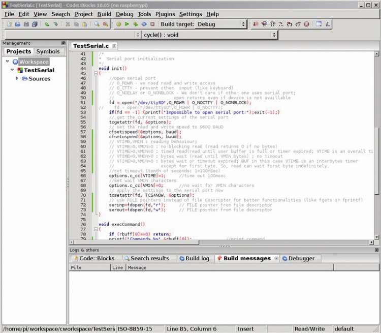
The program TestSerial.c (not to be confused with the Arduino sketch TestSerial seen above) is the source listed in the project and is an example of how to open a serial port to communicate with Arduino. The program opens the serial port, reads data that Arduino sends and displays it on the Linux console. To view it just select it in the Project pane with a double click. To use it you must have a sketch that sends records to Raspberry Pi. Of course, like all programming environments, it allows to proceed in “debug” step-by-step mode or defining the “break-points”. Through the “Debugging windows”, you can open a window for “watches” (reading the contents of the variables) and other.
The comments allow you to describe the basic configuration of the serial port to lay the foundation for a collaborative programming and Arduino usage. On Codeblock website, you will find a manual and other information.
The folder “/ home / pi / workspace / cworkspace” also contains all the programs that have their executable version in “/ home / pi / bin” (but also those used in / etc).
If you wish to integrate the Web Server with your pages, you can put it in “/home/apache-tomcat-7.0.47/webapps/ROOT”. A web-application (.war file) can be loaded via the Tomcat “manager”(username and password: tomcat).
Finally if you want to use CGI scripts, you can place them in “/home/apache-tomcat-7.0.47/webapps/ROOT/WEB-INF/cgi”, but remember to reference as “http: // …. ./cgi-bin / …. “.
In the folder you can find a few sample scripts already.
From the store

Related Posts


One Comment
Leave a Reply
-
 Arduino ISP (In System Programming) and stand-alone circuits
We use an Arduino to program other ATmega without...
- Posted 12 years ago
-

-

-
 GSM GPS shield for Arduino
Shield for Arduino designed and based on the module...
- Posted 12 years ago
-
 Small Breakout for SIM900 GSM Module
Some post ago we presented a PCB to mount...
- Posted 13 years ago
-
 Join Maker Faire Rome 2024: Innovation Unleashed at Gazometro Ostiense | Calls Now Open!
All Calls Now Open for Maker Faire Rome 2024...
- Posted 2 weeks ago
-
 Building a 3D Digital Clock with Arduino
Project to create a digital clock consisting...
- Posted 4 months ago
-
 Acoustic amplifier – in DIY Kit
This kit creates a microphone amplifier with an output...
- Posted 5 months ago
-
 Creating a controller for Minecraft with realistic body movements using Arduino
Project of a controller that maps body movements...
- Posted 5 months ago
-

Pingback: Arduino & co | Pearltrees