- Building a 3D Digital Clock with ArduinoPosted 4 months ago
- Creating a controller for Minecraft with realistic body movements using ArduinoPosted 5 months ago
- Snowflake with ArduinoPosted 5 months ago
- Holographic Christmas TreePosted 6 months ago
- Segstick: Build Your Own Self-Balancing Vehicle in Just 2 Days with ArduinoPosted 6 months ago
- ZSWatch: An Open-Source Smartwatch Project Based on the Zephyr Operating SystemPosted 7 months ago
- What is IoT and which devices to usePosted 7 months ago
- Maker Faire Rome Unveils Thrilling “Padel Smash Future” Pavilion for Sports EnthusiastsPosted 8 months ago
- Make your curtains smartPosted 8 months ago
- Configuring an ESP8266 for Battery PowerPosted 8 months ago
Powering Arduino with Batteries thanks to a Battery Shield
Today we’ll show you how to feed a whole Arduino system from a battery, optimizing energy consumption to ensure that the batteries would provide power to the complete system for few years.
Perhaps, the only shortcoming of Arduino is that there aren’t any sophisticated tools in case you want to use a battery power supply. There are software techniques that help limitg the main clock frequency in order to decrease power consumption; however, in our opinion, those methods are not enough to guarantee acceptable battery life. So far, Arduino has always been equipped with batteries to cope with brief and temporary failures of the power grid but batteries have never been considered as the main source of energy.
The component which requires more energy on any electronic board is definitely the CPU; granting this, all the power optimization efforts went to exploit the ability of modern MCU to go into low power (sleep) mode, in which the CPU is pushed to 100% only for the time necessary to process the input / output. For the most of time, only a few CPU sections remain active.
On the other hand, there are also techniques that address the problem by deciding to turn off the entire board and turn it on only when needed (in response to particular events) or at fixed time intervals, in order to check the status of the inputs and accordingly update the status of the outputs.
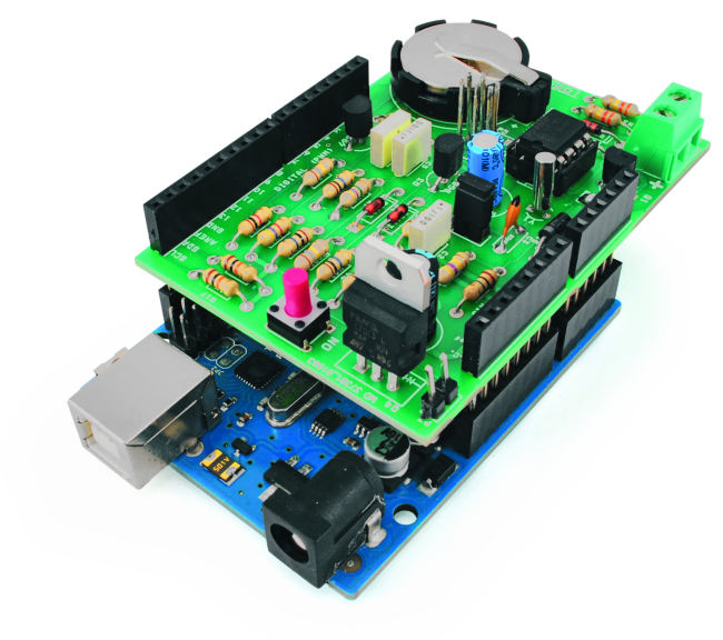
The shield presented in these pages is an expansion board for Arduino Uno; it is set to receive the supply voltage from a battery as input (power supply voltages must be between 5 and 12 volts) and, exploiting a particular feature of the PCF8593T chip (generally used as clock and calendar) allows you to power on the system at fixed intervals (programmable), depending on the conditions found.
As we will see later in this article, the hardware of the shield allows the Arduino software to choose when to be “awakened” and, once powered on (through the state of a digital output), to choose how long to stay on and when to be finally shut down.
Briefly, we can summarize the general logic to be implemented as follows:
– The system is off from a certain time on;
– At some time point, the clock awakens Arduino; the CPU decides to stay awake and to analyze its internal state as well as that of any external pin/sensors;
– Once completed the inputs analysis and after that all outputs have been updated, Arduino programs the clock setting when to be awakened and then decides to go off;
– All the rest of the time, the system is switched off; each time it awakes, the whole mechanism is repeated.
It’s intuitive enough to understand that if the Arduino software is well implemented, optimizing the off period, the whole system can be battery powered ensuring several years of operations.
Clearly, the algorithm presented in this article could be applied when a real-time control it’s not needed: e.g. if the system is not being used to analyze hazardous conditions or if reaction time must be short, and is not suitable for always-online systems. The algorithm is very effective when it is requested to monitor physical parameters that are stable or vary slowly over time (eg: home/environmental temperature, weather stations, ambient light, etc.).
Since the shield includes the PCF8593T chip, it can also be used as a RTC shield to provide the typical features of a clock and calendar.
The shield uses two digital pins (D6 and D7) to manage the power system and the I2C port for communication / programming of PCF8593T. It is possible (setting a jumper) to use the analog pin A0 to read the supply voltage from the battery to identify its charging level. There is also a button to turn on Arduino even during planned shutdown periods (clearly this feature must be implemented during software coding) and a jumper that, if enabled, will keep Arduino always on (to be used for special cases, i.e. connected to a relay on a second board to achieve particular applications).
Battery Shield Wiring Diagram

The supply voltage is supplied through the two poles terminal block JP13; the diode D15 is used to protect the board in case of reverse polarity mismatch.
The most important section of the shield is definitely the one made by the network of resistors R4 – R14, transistors T2, T4 and T5 and diodes D4 and D5. It is through this section that the power supply is connected or disconnected to Arduino, and the board itself can decide whether to be on or off.
As you can see the Arduino pin D7 is the input of the electronic network and, in particular, if D7 is logically high Arduino decides to go off (the Arduino board is disconnected from the power supply). On the contrary, low-D7 is the condition when Arduino decides to stay on. Please note that when Arduino is off, D7 is floating (the state is not physically stable); for this reason, the pull-up R17 keeps the status “high”, maintaining a stable shutdown condition.
The P1 button allows you to turn Arduino on; in fact if P1 is pressed, the negative pole of the supply voltage (through D4) is sent to the base of T2, and then the power supply voltage is supplied to Arduino. Same mechanism for the jumper JP3 which, if closed, performs the same conditions as “P1 button pressed” (i.e. Arduino on).
In parallel to button P1 and jumper JP3, there is a signal from the PCF8593T (INT_CLOCK, that “access” to the network via the BJT T5). The state “high” of the signal INT_CLOCK corresponds to the same logic state “P1 button pressed” and then Arduino is turned on.
Having introduced the chip PCF8593T, let us analyze its relevant section. As you can see it is connected to a 32,768 Hz quartz for the correct timing; there is a capacitor C3 to stabilize the counter and the capacitor C4 to level the supply voltage.
The clock / calendar can be powered by the main battery (if jumper P2 is closed) through the stage T1 which ensures the correct supply voltage according to the battery voltage; alternatively it could be powered by a 3V button cell battery (if the jumper JP2 is implemented).
If the button battery is connected and plugged, it is used during the replacement of the main battery so you do not erase the running configuration of the clock and calendar.
D2 and D3 diodes prevent interactions between the two batteries, avoiding that a battery discharges the other and vice versa.
Last section to analyze is that of the connectors required to connect to Arduino Uno;
as it can be seen, the I2C port pins are used (SDA and SCL; there are pull-up resistors R17 and R18) for communication with the PCF8593T;
the pin D6 and D7 for the management of Arduino trickle power feeding and the analog pin A0 to detect the battery voltage (the divider R15/R16 is necessary to lower the supply voltage to make it compatible with Arduino TTL levels).

BOM
R1: 10 kohm
R2: 330 kohm
R3: 330 kohm
R4: 4,7 kohm
R5: 10 Mohm
R6: 10 Mohm
R7: 4,7 Mohm
R8: 180 kohm
R9: 180 kohm
R10: 1 kohm
R11: 10 Mohm
R12: 10 Mohm
R13: 10 Mohm
R14: 1 Mohm
R15: 1 Mohm 1%
R16: 470 kohm 1 %
R17: 10 kohm
R18: 10 kohm
C1: 220 µF 16 VL
C2: 100 nF 100 VL
C3: 22 pF
C4: 100 µF 16 VL
C5: 100 nF 100 VL
C6: 10 nF 63 VL
U1: PC8593T
T1: BC547
T2: BC557
T3: BC557
T4: P36NF06
D1: 1N4007
D2: SD103
D3: SD103
D4: SD103
D5: SD103
P1: Microswitch
Q1: 32.768 kHz

Arduino Library Battery Shield
To have the system working properly, it is necessary that all the application software is written keeping in mind how the board on/off mechanism is implemented.
To facilitate the integration by the end-users, we have created a software library that implements all the core functionalities. In the library we have defined:
- the “low level” functions (including system initialization, wakeup, auto power on and off the Arduino; reading of the analog value of the supply voltage);
- the “mid-level” functions (including the PCF8593T boot up and wakeup moments);
- the “high level” functions, like those of a typical clock / calendar component (date and time programming and reading; New Year/increase year; daylight saving time, etc).
As we will see later analyzing the programming example, by using these functions the programmer does not have to worry about the direct hardware management: he has a software interface that takes care of everything and hides all the programming details.
The library defines an object “Battery” with the following public methods (that could be used in the Arduino program):
- void begin (): initializes the pin D6 and D7 as digital input and output and starts the clock if it is detected to be stopped;
- void powerON (): lowers the D7 pin so that the Arduino can stay switched on;
- void turnOFF (): mirroroing the powerON (), raises the pin D6 so that Arduino can turn itself off;
- bool onFromButton(): in the hardware scheme we have seen that there is a button to turn on the Arduino bypassing the clock; to distinguish if the wake up was carried out by PCF8593T or by pressing the button we use the Arduino digital pin D6. By calling the function onFromButton() we test the state of D6 and consequently identify if the switch derived from the button (the function result true) or clock (result false);
- float getBatteryVoltage(): as seen by analyzing the circuit blueprint of the shield, you can use the Arduino analog pin A0 to detect the battery voltage. This function can be used to read its value; the function is already performing all conversions and takes into account all the different components voltage drops (in particular the diode D1) and returns (floating point number) the voltage of the battery;
- void startSecAlarmPCF8593, void startMinAlarmPCF8593, void startHourAlarmPCF8593: With these functions you can schedule the next wake up event. In particular, you can specify (taking as reference the execution timestamp of the functions), respectively, the number of seconds, minutes or hours Arduino must be turned off before being awakened by the clock. The functions accept as input one byte whose valid values are between 1 and 99 (extremes included);
- void writeClockANDDataPCF8593 (): as said before, the component PCF8593T can also be used as RTC and clock / calendar. This function allows you to program the current date and time (passed as parameters: hours, minutes, seconds, day, month and year). The function determines and programs automatically the day of the week and the daylight saving time condition;
- void readClockANDDataPCF8593 (): it allows you to read the current date and time indicated by the chip PCF8593T. As a calendar, the values returned are day, month, year and day of the week; As a clock, the values returned are hour, minutes, seconds and hundreds of a second;
- bool checkProgrammedPCF8593 (): allows you to test if the clock / calendar of PCF8593T have been initialized and programmed. If so, the function returns true otherwise it returns false (in this case the chip shall be initialized by calling the appropriate function);
- bool checkHourLegPCF8593 (): allows you to check whether a given day (identified by day of week, day and month) is on daylight saving time or not (useful to manage this passage automatically);
- void checkNewYear (): checks if a new year is begun and, if so, updates (incrementing by 1) the year number;
- byte getDayOfWeek (): Determines the day of the week for a date (identified by the day, month and year);
- bool YearBisestile (): Determines if a given year is a leap year.
Example 01 Arduino Firmware
#include <Battery.h>
#include <Wire.h>
#include <Serial.h>

const int pinBoardLed = 13;

Battery batteryShield;

void setup() {
  pinMode(pinBoardLed, OUTPUT);
  digitalWrite(pinBoardLed, HIGH);

  Wire.begin();
  Serial.begin(115200);

  batteryShield.begin();
  batteryShield.powerON();

  if (batteryShield.onFromButton() == true)
    Serial.println("ON from switch");
  else
    Serial.println("ON from RTC");

  Serial.println(batteryShield.getBatteryVoltage());
}

void loop() {
  delay(2500);

  batteryShield.startSecAlarmPCF8593(10);
  digitalWrite(pinBoardLed, LOW);
  batteryShield.turnOFF();
}
To understand the workflow and programming logic to be used with the battery shield, let’s look at an example. The software does nothing but programming the Arduino battery shield, aiming at keeping the board off most of the time; it wakes Arduino up every 10 seconds; simulates the execution of a program (simulated by a delay) and then switches the board off waiting for the next execution cycle.
After the inclusion of the libraries used (in particular the “Battery.h” specific for the shield), it is defined the digital pin for the Arduino board LED management and is declared a “Battery” object that will be used for the management of the shield itself.
In the Arduino setup function (which is the first run at startup) the LED pin is programmed and it is turned on; then the libraries “Serial” and “Wire” are initialized (the former used as a debugging tool, to clarify the software flow).
Following on, it is initialized the object “batteryShield” (batteryShield.begin() function); this function was written to initialize all the resources (both hardware and software) that will be needed for the management of the shield (in order to “hide” to the user all the low-level implementation details).
The next instruction is the “batteryShield.powerON ()” which configures the shield (in particular the digital pin D7) so that Arduino is constantly fed (in practice it is a sort of self-supply through which Arduino decides that it should be kept always ON).
Recalling “batteryShield.onFromButton ()”, it identifies the cause of wake up (ON button or clock programmed) and, consequently, a message is sent on the serial debug.
Following, it is read and sent to the serial debug port the supply voltage of the battery; we note that the value displayed is the real battery voltage, since it takes into account all the voltage drops due to various diodes and resistive dividers.
At this point, the Arduino software is running and the board, in these conditions, is always powered (clearly taking into account the physical limits of battery capacity).
After “setup ()” is ended, “loop ()” is being executed: the first instruction is a delay (approximately 2.5 seconds) which simulates the operation of a generic main program (read input, set output, …).
The next board wakeup is set after 10 seconds (command “batteryShield.startSecAlarmPCF8593 (10)”) , the LED is turned off and then whole system is switched off (command “batteryShield.turnOFF ()”). The latter instruction is blocking: after setting the digital pin D7, it enters in an infinite loop (until power is physically cut, that is when the board is turned off).
After the 10 seconds programmed, the chip PCF8593T switches on the board and the whole mechanism is repeated (the software starts from the “setup” as in the first boot).

Example 02 Arduino Firmware
#include <EEPROM.h>
#include <Battery.h>
#include <Wire.h>
#include <Serial.h>

const int pinBoardLed = 13;

Battery batteryShield;
void setup() {
  pinMode(pinBoardLed, OUTPUT);
  digitalWrite(pinBoardLed, HIGH);

  Wire.begin();
  Serial.begin(115200);

  batteryShield.begin();
  batteryShield.powerON();
}

void loop() {
  int contatore;
  contatore = (((int) (EEPROM.read(0x0000)) << 8) + (int) (EEPROM.read(0x0001)));
  contatore++;
  Serial.println(contatore);
  EEPROM.write(0x0000, (byte) (contatore >> 8));
  EEPROM.write(0x0001, (byte) (contatore & 0x00FF));

  batteryShield.startSecAlarmPCF8593(30);
  digitalWrite(pinBoardLed, LOW);
  batteryShield.turnOFF();
}
Let us now look at a second example of the Arduino code (refer to list in the box “Sample Battery Shield 02”). This uses the shield capabilities to program a “power on” every 30 seconds and store a wakeups counter (16bit, in an EEPROM).
Also in this case, the libraries must be included (in particular the “Battery.h” specific for each shield); we define the digital pin to trigger the Arduino LED and finally we define an object “Battery” that will be used to access the shield.
In the Arduino setup function you turn on the LED pin; then you start the “Wire” and “Serial” library (the latter used as a debugging to clarify the software flow).
Moving on, it is initialized the object “batteryShield” (function batteryShield.begin ()) in order to init all the resources (both hardware and software) that will be needed for the management of the shield.
The next instruction is “batteryShield.powerON ()” that indicates to the shield to keep Arduino constantly fed.
At this point Arduino software is running and the board, in these conditions, is always powered.
After “setup ()” is ended, “loop ()” is being executed: the first instruction reads the first two bytes of EEPROM and uses them to “build” the 16-bit “power on events” counter; this counter is incremented and the value is updated on EEPROM (as debugging, the same counter is also sent to the serial port).
Next instruction is to plan the farther wake up (command “batteryShield.startSecAlarmPCF8593 (30)”) after 30 seconds, turns off the LED and then switches off the whole system (command “batteryShield.turnOFF () “). After the 30 seconds programmed, the chip PCF8593T switches on the board and the whole mechanism is repeated (the software starts from the “setup” as in the first boot).
The execution time of this example is certainly faster than the previous; you will notice that the board is powered just a few moments while most of the time it is off. We therefore created what was in our initial plans: a low current consumption setup powering the Arduino board only for the time that is necessary to the execution of the given code.
Any ideas on contexts to use it? Let us know in comments!
From the store

Related Posts


6 Comments
Leave a Reply
-
 Arduino ISP (In System Programming) and stand-alone circuits
We use an Arduino to program other ATmega without...
- Posted 12 years ago
-

-

-
 GSM GPS shield for Arduino
Shield for Arduino designed and based on the module...
- Posted 12 years ago
-
 Small Breakout for SIM900 GSM Module
Some post ago we presented a PCB to mount...
- Posted 13 years ago
-
 Join Maker Faire Rome 2024: Innovation Unleashed at Gazometro Ostiense | Calls Now Open!
All Calls Now Open for Maker Faire Rome 2024...
- Posted 2 weeks ago
-
 Building a 3D Digital Clock with Arduino
Project to create a digital clock consisting...
- Posted 4 months ago
-
 Acoustic amplifier – in DIY Kit
This kit creates a microphone amplifier with an output...
- Posted 5 months ago
-
 Creating a controller for Minecraft with realistic body movements using Arduino
Project of a controller that maps body movements...
- Posted 5 months ago
-

Pingback: Peripherals | Pearltrees