- Building a 3D Digital Clock with ArduinoPosted 4 months ago
- Creating a controller for Minecraft with realistic body movements using ArduinoPosted 5 months ago
- Snowflake with ArduinoPosted 5 months ago
- Holographic Christmas TreePosted 6 months ago
- Segstick: Build Your Own Self-Balancing Vehicle in Just 2 Days with ArduinoPosted 6 months ago
- ZSWatch: An Open-Source Smartwatch Project Based on the Zephyr Operating SystemPosted 7 months ago
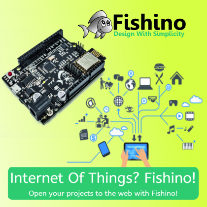
- What is IoT and which devices to usePosted 7 months ago
- Maker Faire Rome Unveils Thrilling “Padel Smash Future” Pavilion for Sports EnthusiastsPosted 8 months ago
- Make your curtains smartPosted 8 months ago
- Configuring an ESP8266 for Battery PowerPosted 8 months ago
FISHINO: Arduino becomes wireless
Why “Fishino” ?
The names comes to a joke made on April Fools’ Day (in Italian “Pesce d’Aprile“, and ‘Pesce‘, which sounds ‘pashe’ means Fish) made on an Arduino forum where we “presented” a new board named “Fishino Zero” which had revolutionary technical specs.
The symbol, placed on board’s picture with a graphical editor, was the small fish which became the actual logo.
The joke was quite successful, and the idea of building such a board soon appealed to us.
The ‘UNO‘ part was then added to symbolize the first board of a series and to mark the complete compatibility to Arduino UNO boards, both in term of connectivity and size.
Another Arduino clone?
Not exactly. With this board we aimed to combine the easy-of-use and the enormous amount of available libraries of Arduino with internet connectivity, an almost unlimited memory storage thanks to microSD card slot and, last but not least, an on-board RTC with battery backup, all that at a fraction of the price of an original Arduino with the equivalent set of shields, without increasing board’s sizes beside the tiny 7mm wifi antenna overhang.
The integration of aforementioned periferals, in our opinion a must in IOT era, allows the creation of an huge set of appliances which can both be controlled via Internet and upload recorded data to it.
Among the possibilities, all achievable without additional hardware are, for example:
- Home automation systems, manageable with a web browser
- Portable data loggers which can upload data to internet automatically when a WiFi connection becomes available
- Net-controlled Robots that can also transmit sensor data over Internet
The usage of a low-cost WiFi module but with customized software to get high performances, which can be used as a WiFi station, access point or both, permits control from a smartphone even in absence of a WiFi connection.
Future ability to upload sketches via WiFi (work in progress), already foreseen on hardware side, will permit to update the appliances with no need of a physical connection to a personal computer.

Technical specs
- Fully compatible with Arduino UNO
- WiFi module on board, can be uses in station mode, access point mode or both
- MicroSD slot on board
- RTC (Real Time Controller) with backup lithium battery on board
- Largely increased current on 3.3V supply section
- A new connector added to solve the well known Arduino’s problem of incompatibility with breadboards
Schematics
Power supply
Fishino UNO, as Arduino UNO, can be powered via USB port or an external power connector.
Supply gets automatically switched from USB to external when latter voltage (or voltage at Vin pin) is enough for linear regulator IC5.
Let’s see it in depth.
Voltage coming from supply connector pass through Schottky diode D2 used as a reverse voltage proection. We chose a Schottky diode instead a bipolar one because of low voltage drop of former (around 0.3-0.4 volt max instead of about 0.75 of bipolar diodes); this, and the usage of a low-dropout linear regulator allows powering already from a 6.6 volt source (5 for the board + 0.4 on diode + 1.2 of regulator’s dropout). The maximum allowed supply voltage depends on regulator’s thermal dissipation; we suggest to not go over 12 Volts and, if possible, to stay below around 9 Volts. The regulators has anyways an internal thermal protection which disables it when heat becomes excessive.
Vin input voltage (after protection diode) goes also to op-amp IC1A used to switch supply from USB port.
When Vin is greater than 6.6 volt the non-inverting input of op-amp, used here as a comparator, halved by resistor divider made with R1 ed R2, overecome the 3.3 reverence voltage of inverting input makin output switch to positive (high) level, blocking so P-Channel mosfet T1.
A close look at mosfet shows an apparently weird connection : supply enters from Drain and comes out from source, treaversing at same time the interal clamping diode. Supply pass through the diode even if mosfet is turned off.
What’s then the purpose of mosfet ? Apparently a diode would be enough : if cathode voltage is greater than anode’s one (USBVCC) diode switches off disconnecting so the USB power.
The reason of the mosfet (and annexed circuits) is to avoid diode dropout, which would lower the power supply coming from USB port from 5 volt to abiut 4.2-4.6 volt. This dropout is avoided when mosfet switches on.
Last supply stage is made by linear low-dropout regulator IC3 which brings the 3.3 volts needed, among others, by SD card and WiFi module.
Unlike original Arduino (and most clones), which brings few tenths of mA on 3.3 volt line, Fishino is able to provide around 7-800 mA, depending on current absorbtion on 5 Volt line.

USB interface
Unlike oroginal Arduino, USB interface has been built around a CH340G chip in replacement to the more common FTDI232 or other more or less complicated solutiones.
The choice came mostly from lower cost and circuit simplicity keeping same performances.
The chip needs few external components to operate : a 12 MHz crystal (Q1), due capacitors in oscilator pins (C2 e C3) and a decoupling capacitor for the internal 3.3V regulator (C4).
The chip can be indeed powered from a 3.3 volt supply (connecting V3 pin to Vcc) or from a 5 volt supply, adding the V3 pin decoupling capacitor.
The component brings all RS232 signals, which are the Receive and Trasmit ones (Rx and Tx) and all control signals (CTS, DSR, DXD, DTR e RTS),
In our circuit we only use data signals (Rx and Tx) and the DTR to generate the auto-reset pulse when serial port is opened, which allows sketch upload without need of a manual reset.
More on reset circuitry later on, as unlike original one it has been modified to allow remote uploading of sketches over WiFi.
The USB interface chip doesn’t provide 2 separate outputs for Tx and Rx leds (which shows activity on respective pins), so we put the leds on data signals directly, with a careful choice of resistance values to bring enough led lightning without eccessive power drawing.
The choice of resistances values has also been trimmed to avoid flashin of WiFi module’s firmware from on-board USB interface, without need of an external adapter.
Atmega328P controller
This section is almost identical of original onee; same controller, only in SMD format because of board’s space constraints, with the usual 16 MHz crystal, the 2 capacitors around it, and some decoupling capacitors on supply pins.
A note about latters : in most schematics we can see some (often many) small capacitors in parallel between power supply line and ground. Some people asked why we can’t simply use a big capacitor in replacement of those.
Looking in depth at boards we can see that all these small capacitors are placed very close to IC’s supply pins.
The reason is quite simple : modern digital chips runs at high frequencies and with pulsed signals, which cause strong current absorption variation on supply pins.
Because of the high frequencies the pcb traces, normally quite thin and long, behave as inductors or, at those frequencies, as resistors, causing electrical noises on pins.
Capacitors placed very near to supply pins eliminate most of those noises.
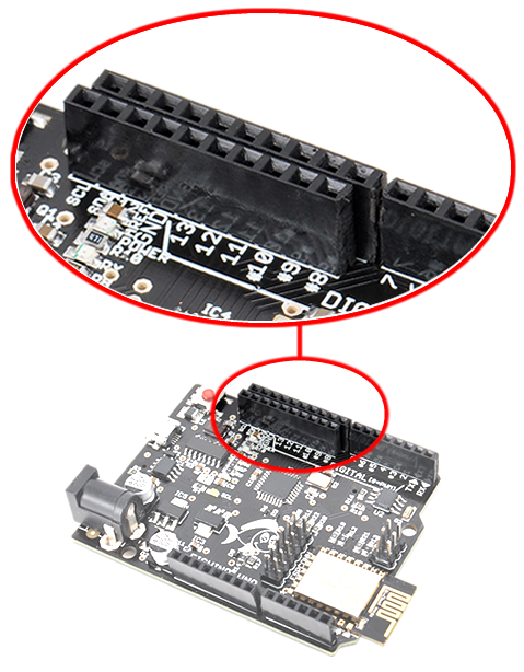
About I/O connectors : as you can see from pictures, we added a small 10 pins connector in parallel to the standard one, but slightly shifted, to align it to 2.54 mm standard pitch. This allows to use a standard breadboard as a shield, overcoming the well known Arduino’s problem, without breaking compatibility with existing shields.
SPI interface – Level shifters
Almost all Fishino‘s circuits operates with a 5 volt supply and signals, but MicroSD cards and the WiFi module do on 3.3 volt e, worse, they’re not 5v-tolerant.
Non 5v-tolerant circuits can be damaged with signals from 5v ttl levels.
Well, for the WiFi module, from datasheet it seems that it’s indeed 5v-tolerant, but it’s not clear enough, so we behave as it is not, even if in all our tests we couldn’t damage it with 5v signals. This indeed doesn’t mean that it can’t be damaged in long term usage.
So, to follow technical specs we decided to insert some level-shifting circuits.
Those are built with simple resistor dividers, in 5V to 3.3V direction; in the opposite direction we trust on high 3.3v ttl level to be inside the high 5v ttl level range; this theoretically lowers noise-rejection capabilities, but in our and most circuits works flawlessly.
Doing so we’ve spared complicated solutions which, besides of increasing costs, would have taken precious board space. Better solutions needs indeed a mosfet plus a couple of resistors for each signal, or dedicated level shifter ICs.
The only “caveat” of used solution, if we want to be picky, is that resistor dividers have 2 opposites requirements :
- they shall have an high enough impedance to not overload atmega328p’s outputs and to not waste unneeded power supply current
- they shall have a low enough impedance to avoid signal lost and delays due to input capacitances, in particular with high-frequency signals.
Chosen values are a compromise between the 2 requirements above and allow perfect data transmission at highest speed available. The dividers are built around resostors pairs R13-R21, R12-R19 e R14-R17. A 5 Volt input value gets converted to:
Vo = 5 Volt · 3.3K / (1K + 3.3K) = 3.83 Volt
A value which is slightly greater than the theoretical 3.3 volt but it’s still acceptable from specs, which allows usually values up to 0.6 Volt greater than supply, so 3.3 + 0.6 = 3.9 Volt.
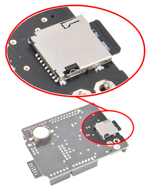
MicroSD card interface
The interface is quite simple and is almost identical to SD shield or compatible ones, or to SD interface card bundled with WiFi / Ethernet shields; it uses SPI data lines which are MOSI (data from atmega to SD, Master Out Slave In), MISO (data from SD to atmega, Master In Slave Out) e SCK (clock). Atmega lines are, of course, adapted by level shifters described in previous paragraph.
Card selection is done by SDCS line, active low. On this line level shifting is a bit different, using a pullup resistor on 3.3 Volt supply (R18) and a diode which allows just negative signal coming fm atmega.
This kind of shifter allows the SD to be de-selected when SDCS signal (connected on Fishino‘s digital output 4) is in tree-state mode, for example after a reset.
The SD interface is fully compatible with similar shields, and it can use same existing libraries, as we will see in examples shown later.
WiFi module
If atmega controller can be regarded as Fishino‘s brain, the WiFi module is indeed it’s door to external world, and it’s the main reason of board’s development.
The idea arose, indeed, from the need of an Home Automation appliance which could be controlled from web.
This is not a new idea, of course, but before Fishino board we needed an Arduino with annexed WiFi or Ethernet shield and a separated RTC, with costs and sizes by far higher and, with Ethernet, a wired network connection.
WiFi module embedding in Fishino at reasonable price has been possible thanks to new WiFi modules with ESP8266 controller.
This modules, although very small in size, are built around a 32 bit processor, a big flash memory chip (from 1 to 4 MBit), around 90 KBytes of RAM, of which 32K available for user’s applications, a complete WiFi stack up to a PCB integrated antenna.

At first sight such a processing power (by far greater than atmega controller’s) would suggest the direct usage of WiFi module, programming it directly with producer’s SDK (Software Development Kit, quite complicated usage) or with a set of software tools which allows to code with Arduino IDE directly.
Where are the caveats ?
First, architectures are quite different; even if Arduino IDE has been patched to build and upload ESP code directly, compatibility is still too low to be usable.
Next, we’d loose the ability to use the enormous amount of existing Arduino’s shields and libraries.
Last but not least, ESP has a very limited amount of I/O digital pins and just one analog input, which is a big limitation to real world usage.
So we decided to embed the WiFi module in an Arduino compatible board , trying to minimize differences with existing WiFi / Ethernet shields on software side, thanks to a provided library which will be described later.
ESP module’s usage was difficult on the beginning, and source of many trial-and-error phases, mostly because of supplied producer’s firmware.
The latter works sharing data over a serial port and not, as Arduino’s shields, over SPI one.
Serial port’s advantages are obvious: simple usage (with just a serial terminal you can ‘speak’ whith module’s firmware) and the need of just 2 controller’s data lines.
Serial port has also some serious caveats :
- Limited speed. Serial port can be run at 2-300 Kbps at most Higher speeds are possible but do need short connections and a fast controller.
- Missing of handshake. Even if serial handshake lines are foreseen on ESP modules, provided firmware doesn’t use them, end it’s so impossible to stop data transfer from module to atmega controller.Just think to open a web page containing some tenths to hundreds of kilobytes of data (quite usual on to day web pages), which gets sent from ESP to Fishino‘s atmega with its 2 KBytes of ram and you’ll see the problem.
- Need of an hardware serial port on Fishino‘s side, to be able to operate at decent speeds. Software serial is simply too slow to overcome the limit of about 57 KBauds.
So after many trials spent on developing an Arduino library using official firmware, we gave up and decided to develop an in-house one, allowing data transmission over SPI interface which is much faster than serial port and provides handshake.
In spite of a longer development process (ESP documentation is not very complete) the advantages arose immediately :
- Speed. SPI bus can use a clock up to 8 MHz on a 16 MHz clocked atmega. Even considering protocol’s overhead (also present in serial port mode) attainable speed is an order of magnitude greater than serial port one, so about 10 times faster.
- Handshake. SPI protocol is fully handled by master (the atmega, here). The controller do data requests just when he’s able to process them and must not run after the WiFi module.
- Ability to move most of processing and memory requirements from atmega to ESP processor, which has greater capabilities (just thing on 32 K of available ram against 2K or atmega, or a clock of 80/160 MHz against 16 Mz).
- Ability to encapsulate all module’s functions in an Arduino library which is almost identical to original WiFi/Ethernet standard ones.
Developed firmware and annexed library allows to reach data transfer speeds (measured from SD card to browser in a tiny web server environment) of about 60-70 KBytes / Sec, so slightly faster than speed reached with cabled Ethernet shield (!!!) and quite faster (2-3-4 times) than original WiFi shield; the software has still some optimization margins which will be exploited in next releases.
Next firmware releases will also add new features, like usage of ESP hardware serial port as a second Arduino’s hardware serial port, the ability to upload sketches over WiFi and others.
Let’s go now to WiFi section schematics, which has some peculiarities dues mostly because of hardware problematics of ESP modules.
As you can see from module’s symbol, it has many connections named GPIOxx (General Purpose Input Output) which are, as name indicates, used for different tasks depending on firmware program and/or on module’s state.
All pins are indeed usable as the digital I/O (and an analog input) of Arduino, but most of them have also other functions, some of which are used on ESP module boot phase, with make their usage cumbersome.
Here a short pin description:
- GPIO0 and GPIO15 : besides digital I/O function, they’re used to select module’s boot mode. ESP module can indeed boot from internal flash (normal behaviour, GPIO15 at 0 e GPIO0 at 1), from serial interface, used to flash firmware (GPIO15 at 0, GPIO0 at 0) and from an external SD card (we never use this mode, GPIO15 at 1, GPIO0 irrelevant).Just to make stuffs a bit more complicated, GPIO15 pin is also used to select the module in SPI slave mode, active low.So, the module must be started with GPIO15 ad 0 e, short after boot, latter must be set to 1 to free SPI port which is also used, for example, by SD card.
- GPIO12 (MISO), GPIO13(MOSI) e GPIO14(SCK) besides being generic digital I/O, together with above mentioned GPIO15 pin are used by SPI interface.
- GPIO16, generic I/O pin, used also to “awake” the module from deep sleep mode. We don’t use this mode but needs it as an handshake line to atmega controller. On this pin, shortly after boot, some awaking pulses are output and must be discarded.
- GPIO2, GPIO4 e GPIO5 are free and available as digital I/O pins and will be used in a future firmware release.
- Rx e Tx are module’s serial port data lines and are used also for firmware upload. Next firmware version will make them available as an additional hardware serial port for Arduino code, allowing Fishino to double its serial connectivity.
- CH_PD is module’s enable pin. An high level enables the module, a low level disables it lowering power usage to almost zero
- RESET ESP hardware reset pin, active low
- ADC is the input of ESP A/D converter, which has a resolution of 10 bits, so greater than atmega’s A/D converters.
All those pins are (probably) NOT 5v-tolerant, so be careful on its usage.
Schematics peculiarities :
- The D5 diode is used when Fishino (and also ESP module, see more later on) is reset, to keep GPIO15 at a low level forcing the boot from internal flash (or serial port) and NOT in SD card mode.Without this diode a random value on GPIO15 pin would make boot impossible.
- The R23 resistor from GPIO16 to ground signals atmega controller that the module is busy in boot phase, when GPIO16 pin has still not been set as the handshake pin. Software library uses this pin to track the end-of-boot state of module.
As you can see from schematics, we used same data lines as standard WiFi / Ethernet shields, which guarantees a 100% compatibility with additional shields and modules.
ESP connector
On this connector we put some of the free ESP GPIOs (to be used as digital ports) and prevision for some configuration jumpers.
In detail :
- PINS 1-2 : bridging these pins will disable completely the ESP module. Useful if you don’t need it or you’ve a shield that it’s incompatible with Ethernet / WiFi ones.You can also connect pin 2 to a Fishino‘s digital output putting the WiFi enable under atmega’s control.
- PIN 3 : RESET. A low level on this pin will reset BOTH WiFi module and atmega controller
- PIN 4 : ADC. 10 bit resolution ESP’s A/D converter input.
- PIN 5 e 6 : ESP-RX ed ESP-TX. The module’s hardware serial interface. Used also for firmware upgrade.
- PIN 7-8 : GPIO5 e GPIO4. Generic digital I/O.
- PIN 9-10 : a bridge on this pins, followed by a RESET, enters the flash upgrade mode of ESP module. We will describe later details on upgrading.PIN 10 has also the function of GPIO0, usable as a generic digital I/O.
- PIN 11-12 : bridging those pins will enable the (future) sketch uploading over WiFi. This feature is by now foreseen in hardware but not yet implemented in firmware.PIN12 has also the funcion of GPIO2, usable as a digital I/O line
RESET circuits
As mentioned above, RESET circuits are somehow different from Arduino’s original ones for following reasons :
- We need to reset BOTH the atmega end the ESP module on reset button push and/or on IDE’s flashing requests
- To be able to flash atmega controller from WiFi, ESP module must be able to reset the atmega alone without auto-resetting itself
We start from DTR signal coming from USB controller (IC2 / CH340G). This signal, as aforementioned, is set to a low level when serial port is opened on host PC. A negative pulse is formed by aid of C6 capacitor (1 uF ceramic, in replacement of the 100 nF found on Arduino, to have a wider reset pulse), passes through SMD jumper SJ1 (which can be cut to disable auto-reset feature) and reaches “external reset line”, which is connected to reset button and pin number 5 on ICSP connector.
As a difference from original circuit, in Fishino a diode (D6) separates atmega reset input from reset line. The purpose of this diode (and D3 diode, explained later) is the ability to reset the atmega alone without transmitting reset signal to ESP module.
In short:
- pushing RESET button or opening serial port, reset pulse reaches both atmega (passing through D6) and the ESP module directlty, resetting both.
- a reset signal on ATRES-ESP line, generated from WiFi module (if remote programing feature is enabled) reaches atmega reset line passing through D3 diode but, because of D6, can’t reset ESP module back.
With this ‘trick’ we gave WiFi module the ability to manage atmega reset pin and, along with SPI interface, to program it directly even without the presence of a bootloader on chip.
In practice, once the firmware will be ready, it will be possible not only to reflash remotely the atmega controller but also to do it without need of a preloaded bootloader, giving user more space for sketches.
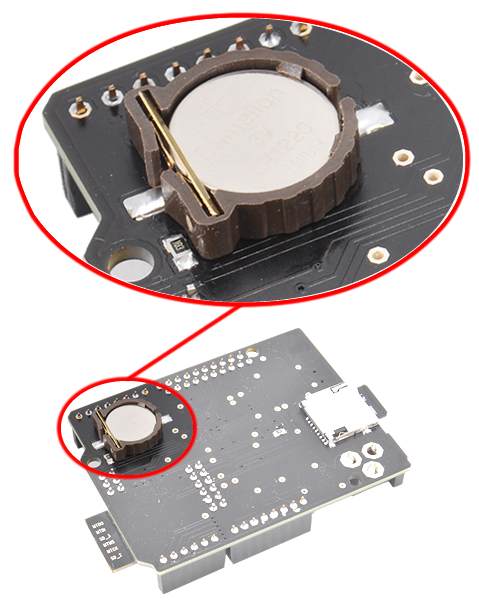
RTC module
We end schematics description with the RTC (Real Time Clock), built around a well known DS1307 chip from Maxim, a 32 KHz crystal, a lithium backup battery ad a couple of pullup resistors on I2C line.
The module is exactly a copy of Maxim’s application note and is fully compatible with Arduino RTC libraries; all chip functions are managed by I2C line (SDA/SCL).
USB drivers
We’ve already seen that Fishino uses an USB/Serial adapter built around CH340G chip, which needs his own drivers, at least for Windows OS up to version 7. It seems that starting from version 8 the drivers are embedded on OS. On Linux OS drivers are already included in kernel.
Windows drivers can be downloaded from site, in Download section.
WiFi module firmware upgrade
Fishino ships with latest firmware version available at assembly time. Being the firmware in constant development, we suggest to do an update before using it the first time and to repeat it periodically, as Arduino Fishino libraries are also constantly updated with new firmware’s features.
Upgrade process is greatly simplified by a downloadable application, available both for Windows and Linux platforms, wich does all needed steps automatically.
Upgrade steps :
- Flash a sketch on Fishino which do not use hardware serial port. The BLINK example is perfect for this purpose.
This step is needed to avoid conflicts on serial port which will also be connected to ESP module.
If the application is unable to locate Fishino port, the problem comes likely from a sketch using Fishino’s serial port.
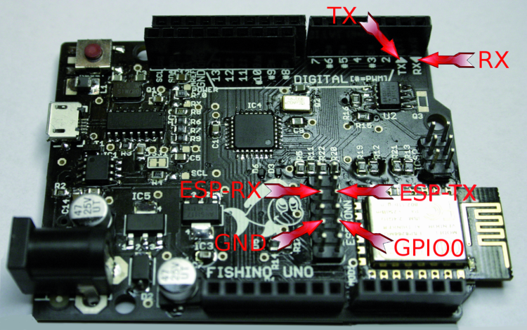
- Connect Fishino TX pin with ESP-TX pin on ESP connector, and Fishino RX pin with ESP-RX pin on ESP connector (see picture at right)
- Connect GPIO0 pin on ESP connector to ground with a cable or a jumper ( see picture at right)
- Connect Fishino to a PC (o press RESET if already connected)
- Run FishinoFlasher application, checking that an internet connection is available.
If all above steps are correct, the application will locate the serial port on which Fishino is connectet, read its model and firmware version, connect to a remote server and download a list of available firmware versions, showing the last one, anyways allowing the selection of an older one in case you want to do a downgrade, as shown in following picture :
Pushing ‘Flash’ button the firmware upgrade procedure will start and a message will be displayed at end.
To exit the firmware upgrade application just press Exit button.
If Fishino is not automatically detected it’s possible to select the port manually, even if it’s likely due to a connection error on steps above.
Manual port selection become useful if you have more than one Fishino connected on your PC; in this case the first one will be automatically detected, but you’ll still be able to choose another one manually.
Once upgrade process is done, it’s enough to remove connections between Fishino‘s pins and it will be ready to be used with new firmware.

Available libraries
Currently we developed a couple of Fishino‘s libraries :
- Fishino library: it’s equivalent to Arduino’s Ethernet or WiFi libraries.
In this library we define FishinoClass object (low level handling, equivalent to EthernetClass or WiFiClass of Arduino), e the 2 client/server objects FishinoClient (equivalent to EthernetClient and WiFiClient) and FishinoServer (EthernetServer and WiFiServer).
Usage is almost identical to Arduino’s equivalents, so all you need to do is to change variables types to match Fishino’s ones to make existing code working on it.
The small differences are related to initialization parts, having Fishino more features than original WiFi shield.
- FishinoWebServer library : it’s the porting on Fishino of the well known TinyWebServer library; it handles a small but complete web server on board
We included also the Flash library in the download bundle, being this one used by FishinoWebServer to spare precious RAM space. This library is also available on internet, we just added it for convenience.
All other libraries are already embedded in Arduino IDE downloads and/or easily available on the web. In detail, we’ll need SD library to handle the microSD card and the RTClib library to handle RTC module, and the other usual system libraries.
Our libraries are still under development, so expect more features on next releases, for example the handling of ESP I/O pins, the ESP hardware serial port and others.
Demo Home Auto
To conclude this article and to allow you to quickly test some of Fishino’s cool features we present in short the FishinoHomeAuto demo.
It’s a small web server that allows handling of Fishino’s digital I/O pins with a web browser and with a nice graphical interface.
Given the complexity of the example, we will just show it in short its setup and usage, in order to make you able o test its features quickly; we’ll write a more detailed description on next article.
We state that the demo is NOT a complete home automation application, but the basis to write your own one; in detail we just handle digital outputs (shown as home lights in following pictures). Software is anyway easily extensible, so we’ll implement more features on next releases, like digital inputs and analog I/O.
Libraries setup
Unpack FishinoLibs.zip file in ‘libraries’ folder inside your sketchbook.
Once done, you’ll find following new libraries :
- Fishino
- FishinoWebServer
- Flash
Listing1
// CONFIGURATION DATA -- ADAPT TO YOUR NETWORK !!!

// here pur SSID of your network

#define SSID ""

// here put PASSWORD of your network. Use "" if none

#define PASS ""

// here put required IP address of your Fishino

// comment out this line if you want AUTO IP (dhcp)

// NOTE : if you use auto IP you must find it somehow !

#define IPADDR 192, 168, 1, 251

// NOTE : for prototype green version owners, set SD_CS to 3 !!!

const int SD_CS = 4;

// END OF CONFIGURATION DATA
FishinoHomeAuto demo setup
- Unpack FishinoHomeAuto.zip file in your sketchbook folder.You’ll get a new folder named FishinoHomeAuto with some files and a folder named STATIC inside of it.
- Copy ALL STATIC folder content (NOT the folder, JUST the files contained in it) in root folder of a MicroSD card.
You don’t need to wipe your SD previous content, just copy the additional file inside its root folder.
The application doesn’t write nor erase anything on SD card, so you can use a microSD card found, for example, in your smartphone.
- Start IDE ed open FishinoHomeAuto sketch.At top of file you’ll find the configuration part, which must be adpted to match your WiFi network .
- Read the comments and do all the changes as requested.
- Save your sketch and flash it on Fishino.
- Insert your MicroSD card on Fishino
- It you want to see some logs of what’s going behind the scenes, open serial monitor.
-
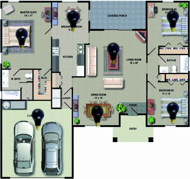
If you want a visual feedback with leds turning on and off following web commands, connect one or more leds (with companions series resistors!) on following Fishino’s pins :
2, 5, 6, 8, 9, 14 and 15
Those are the digital output handled by the demo, each of them has an associated “room” associated inside browser’s floorplan picture. - Press RESET button
- Fire up your web browser (Internet Explorer, Firefox or wathever you use) and put Fishino‘s IP address on address bar (the one chosen when you configured the sketch). If you chose a dynamic IP things becomes more complicated, as you shall find a way to locate Fishino’s dynamic IP, for example looking into your router’s logs.
We strongly recommend a static IP on first tests.
If all is ok, following picture will appears on your web browser .
This page is fully configurable just changing some files in your SD card. Because of tight space here we can’t explain it in deep, so we’ll postpone it to a next article.
Clicking on a light (off at startup, so black color) its picture will change showing an on lamp (yellow) and at same time a led connected to corresponding Fishino’s port will light. Clicking again on same lamp will turn it off again, and so will do the corresponding led:
As said, this demo doesn’t aim to be a complete home automation application but just a small example on how to use Fishino.
Anyway the app is configurable enough to allow you to change the floorplan picture, lights placement and pictures and so on.
We already started the implementation of analog data handling (for example to display a temperature value or to change it) which will be available on next releases.
With this example we conclude Fishino UNO‘s presentation.
On next articles we’ll show some other examples which use all remaining Fishino’s features and new firmware’s extensions.
From the store

Related Posts


5 Comments
Leave a Reply
-
 Arduino ISP (In System Programming) and stand-alone circuits
We use an Arduino to program other ATmega without...
- Posted 12 years ago
-

-

-
 GSM GPS shield for Arduino
Shield for Arduino designed and based on the module...
- Posted 12 years ago
-
 Small Breakout for SIM900 GSM Module
Some post ago we presented a PCB to mount...
- Posted 13 years ago
-
 Join Maker Faire Rome 2024: Innovation Unleashed at Gazometro Ostiense | Calls Now Open!
All Calls Now Open for Maker Faire Rome 2024...
- Posted 2 weeks ago
-
 Building a 3D Digital Clock with Arduino
Project to create a digital clock consisting...
- Posted 4 months ago
-
 Acoustic amplifier – in DIY Kit
This kit creates a microphone amplifier with an output...
- Posted 5 months ago
-
 Creating a controller for Minecraft with realistic body movements using Arduino
Project of a controller that maps body movements...
- Posted 5 months ago
-

Pingback: Arduino WiFi Shield 101 available in USA | Open Electronics
Pingback: Maker Stuff | Pearltrees
Pingback: Happy Open Year! Top 10 OpenSource projects | Open Electronics
Pingback: Raspberrypi Arduino and kits | Pearltrees
Pingback: Fishino: let’s look inside the features | Open Electronics