- Building a 3D Digital Clock with ArduinoPosted 4 months ago
- Creating a controller for Minecraft with realistic body movements using ArduinoPosted 5 months ago
- Snowflake with ArduinoPosted 5 months ago
- Holographic Christmas TreePosted 5 months ago
- Segstick: Build Your Own Self-Balancing Vehicle in Just 2 Days with ArduinoPosted 6 months ago
- ZSWatch: An Open-Source Smartwatch Project Based on the Zephyr Operating SystemPosted 7 months ago
- What is IoT and which devices to usePosted 7 months ago
- Maker Faire Rome Unveils Thrilling “Padel Smash Future” Pavilion for Sports EnthusiastsPosted 7 months ago
- Make your curtains smartPosted 8 months ago
- Configuring an ESP8266 for Battery PowerPosted 8 months ago
Discovering OpenSCAD – part 1: basic functions
Who prints 3D objects needs a 3D modeling and editing software to create and edit files; a good example is OpenSCAD, that is also a nice resource to modify and process most of Thingiverse files.
With “3D modeling” we mean the design of a three-dimensional shape, the generation of the model and its representation in a digital format readable by a computer; It is generally the first step needed in a wide variety of very different applications: for example, to fabricate physical objects with numerical control instruments or also for purely “virtual uses” as 3D computer graphic images or movie-making.
There are two 3D modeling techniques: manual and algorithmic. A 3D model can also be obtained by scanning a real object. The “manual method” handbooks are inspired by the traditional plastic arts manuals, where you manipulate a material up to get it to the desired shape; in algorithmic modeling, instead, you describe the object with programming techniques.
The algorithmic methods are best suited both to achieve high model precision and to reproduce serially similar models.
Talking about computer generated models and file formats, there are many ways: one of the most common, used by several popular software like Blender or Google Sketchup, is using polygon meshes to describe the model outer surface. Another method worth mentioning is the constructive solid geometry (CSG) which describes the entire model volume starting from simple primitives such as cubes, cylinders, spheres and combining each other through unions, intersections and differences.
As you can imagine, obtaining a realistic representation of organic forms with this system requires a lot of work; vice-versa, it is a very suitable system for mechanical parts: in fact, these tend to be easily exploded into geometric primitives and are naturally represented by solid objects rather than by surfaces whose internal shapes are not defined. Depending on the targets you want to achieve, you have to pay attention to several modeling issues: in 3D models it is important the “external” and visual rendering, the surface properties, but when the model must be physically made, the real object structure and its mechanical properties are fundamental.
For this goal, the 3d modeling based on solids is a real help.
OpenSCAD is a free software to create 3D models based on constructive solid geometry, it excels in modeling objects that require precision: from the simplest shape as a rectangular box up to complex structures or mechanisms.
The other very visible OpenSCAD feature is that models are not created by mouse browsing but are described algorithmically in a simple programming language: this is one of the simplest user interfaces that allow you to achieve the accuracy required by CNC applications and also provides useful tools to make composed objects by mathematical formulas.
These features, together with its ease of use, make OpenSCAD a good choice for the hobbyist who wants to add to its electronic projects a structural or mechanical part, 3D printer with a 3Drag or made by using other numerical control tools.
Thanks to all these characteristics, OpenSCAD is one of the most used software that can be found on various model file sharing websites (as Thingiverse).
In this first tutorial we’ll see the OpenSCAD basic functions, enough to create custom boxes for our projects.
The Unitary Cube and other solids
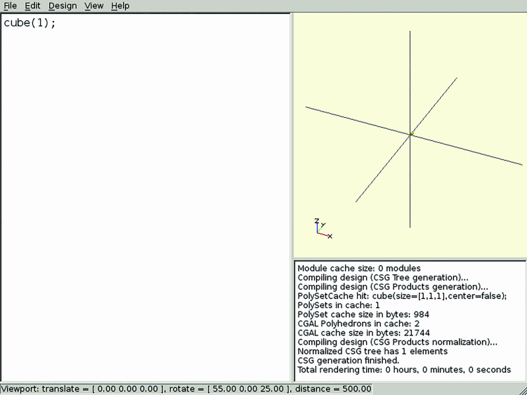
Launching OpenSCAD, we immediately notice that the interface is divided into three parts: the left is the source code area, on the right we have the rendered model area and the third is a section displaying the message log that greets us by showing the GPL license under which the software is released.

If not visible yet, we ask OpenSCAD to show the x, y and z axes in the rendering window (View menu → Show Axes) then we can proceed to describe our first model. In the left section, we write:
cube (1);
we render it by clicking on Design → Compile and our model will be displayed.
OpenSCAD works with absolute units, but its tools generally interpret them as millimeters, so our size 1 cube is really small; to see it clearly we will have to zoom in the point of view: in the render window we can use the mouse wheel to zoom in and out, dragging and pressing the left mouse button will rotate the camera while pressing the right button, it will translate it.
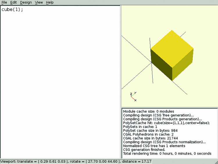
After admiring our cube from all sides, let’s keep on learning the OpenSCAD geometric primitives.
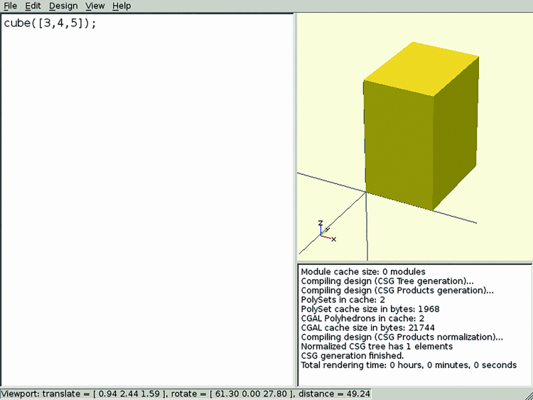
First of all, it must be said that the command “cube” actually draws rectangles: the three axes measures are referred to a vector, i.e. a triplet of numbers in square brackets:
cube ([3,4,5]);
The other two most used solid primitives are sphere, whose only parameter is the radius, and cylinder, which can also draw trunks of cone, specifying the radii of the lower (r1) and upper (r2) bases.

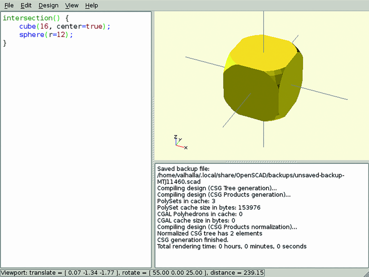
Many primitives then accept the “center” parameter, which draws the model centered on all axes:
sphere (3);
translate ([- 8, 0, 0]) cylinder (r = 3, h = 4, Center = true);
translate ([8, 0, 0]) cylinder (r = 3, r2 = 1, h = 4, Center = true);
Here we also saw our first geometric transformation, translate(), which applies to the next item and moves it according to the array specified as a parameter.
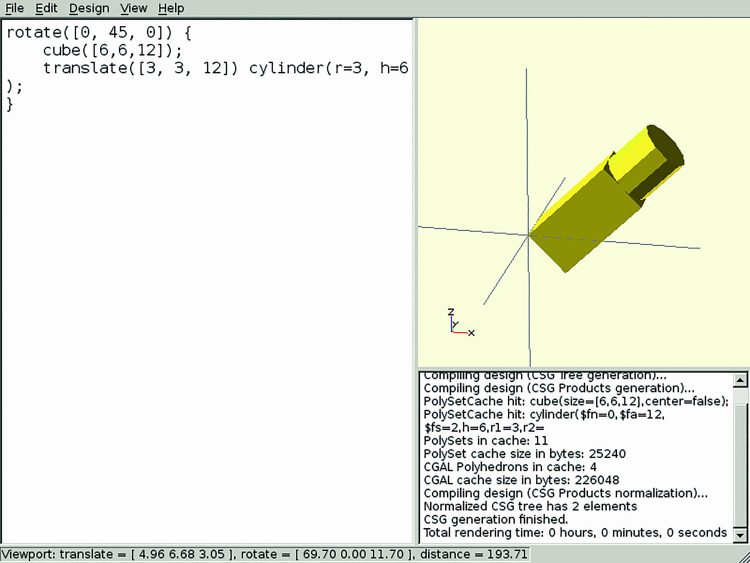
A transformation can also be applied to multiple elements, enclosing them in braces: we apply a shift to a cylinder and a 45 ° rotation to both the cylinder and the parallelepiped:
rotate ([0, 45, 0]) {
cube ([6,6,12]);
translate ([3, 3, 12]) cylinder (r = 3, h = 6);
}
The rotation is described by the rotate transformation, which takes as a parameter a vector with the three axes respective rotation angles. It is important to remember that the rotation center is always the axes origin: so in many cases it is better to model the first component with the right inclination, then translate it to its final position.
Other simple operations are scale, which multiplies the model dimensions by the value provided as a parameter, and resize, that adapts them to “reach” the provided values.
For example, both scale ([0.5,1,1]) sphere (r = 10) and resize ([5,0,0]) sphere (r = 10) will draw a deformed sphere long 5 on the x axe and 10 on other axes.
Finally, mirror is used to obtain a mirror copy of an object and takes as a parameter the vector perpendicular to the plane that mirrors the model. Also for this command, the mirror plane passes through the origin.
The first model
Now, as our first model we can design a simple rectangular box, the base of which will be made up by the difference between two parallelepipeds, one of which is smaller and translated by the wall thickness dimensions:
difference () {
cube ([60, 40, 20]);
translate ([2, 2, 2]) cube ([56, 36, 20]);
}
One important thing to remember is that when you make solids differences and unions, they must not have faces (or parts of) in common, but they must intersect. For example, if the second parallelepiped above was cube ([56, 36, 18]), OpenSCAD would not have been able to determine how to handle the top face, and would not generate a valid model.
To avoid these problems, when you can’t modify the dimensions so much, you can simply add or subtract 0,01 to the respective measure: it is such a small difference that you will not notice in the finished model, but enough to OpenSCAD to distinguish internal and external objects.
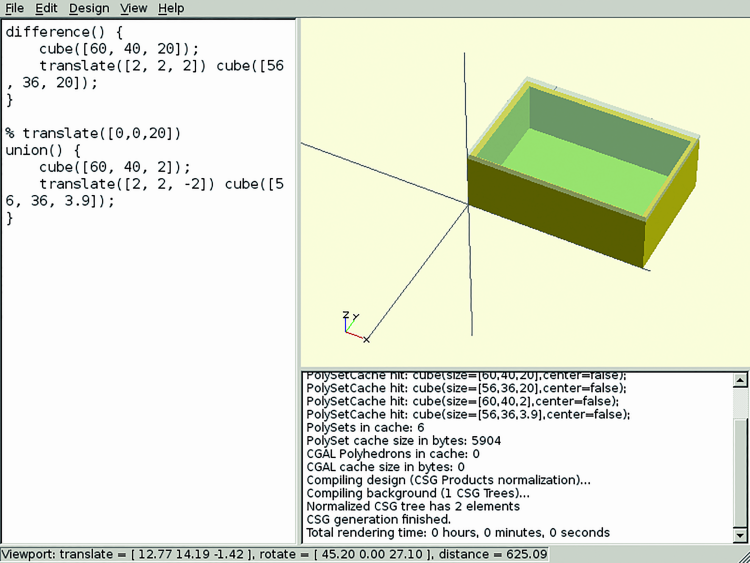
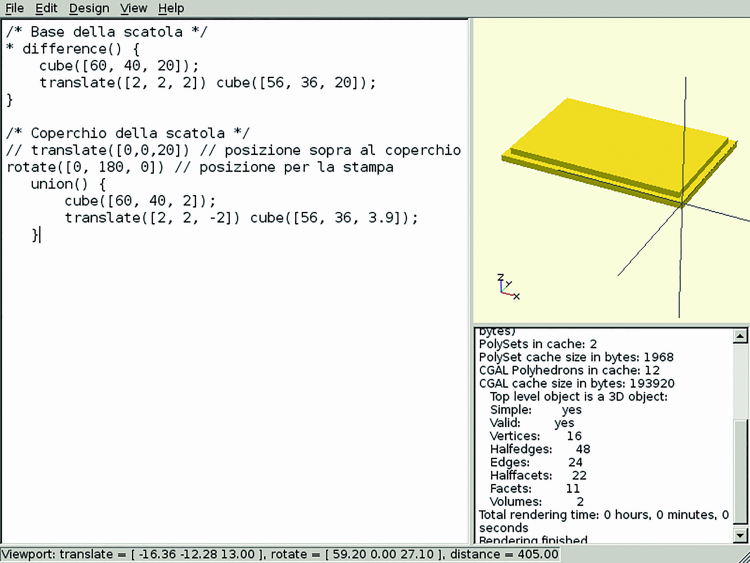
The box lid, however, will be formed by joining two parallelepipeds, one as wide as the box and the other narrower so to fit together; here is how it is constructed:
translate ([0,0,20])
union () {
cube ([60, 40, 2]);
translate ([2, 2, -2]) cube ([56, 36, 3.9]);
}
Compiling this file, you will think to see a solid parallelepiped, as shown in figure.

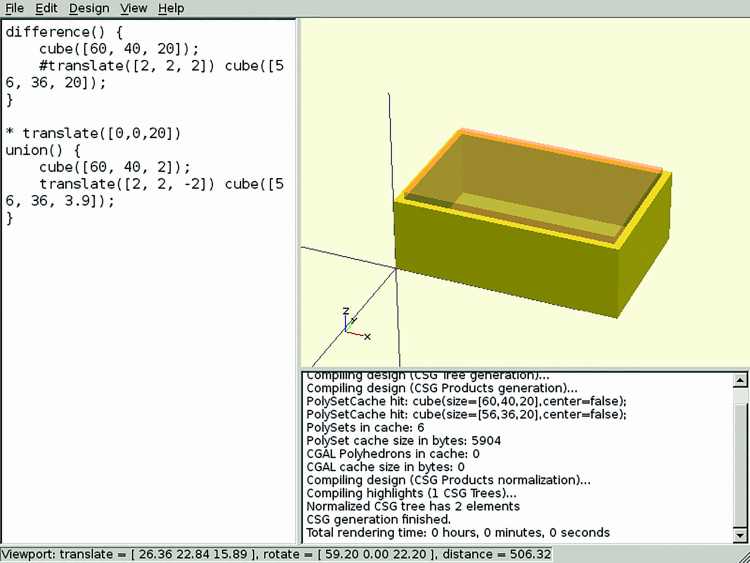
We can, however, take advantage of OpenSCAD modifiers to better visualize the object structure: typing a % before an object, it will ignore that object in the model composition, but it will be displayed in transparent gray, as seen in figure.
Other supported modifiers are: *, that totally excludes a component from the model; ! on the contrary will only render the specified component and # that uses the component normally, but draws it in transparent pink; the latter, for example, is useful for checking the correct components positioning of those removed by the model with the difference command.
As you would expect from a programming language, you can add comments. OpenSCAD uses comments in C ++ style and you can insert a comment to a single line with //, while / * and * / delimit multiple comment lines.
Let’s complete our first model with some descriptive comments and save the file with “.scad” extension. Before it can be exported in STL format ready to be printed, we have to make one last step: with the command Design → Compile and Render (CGAL) we properly compile and render the model and after a few seconds, when the image appears, we can finally use the Design → Export as STL… command.
The result is shown in figure.
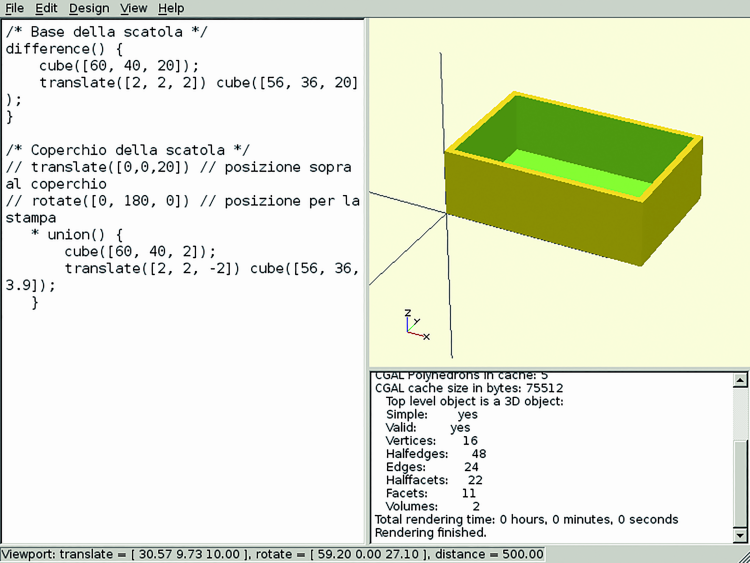
In order to model the lid too, you have to simply remove the * modifier from the lid object line, put it to the base and then uncomment the line with the rotation command, which makes sure that the lid is printable without any supporting structure; Now just run again Design → Compile and Render (CGAL) and then Design → Export as STL …
Box for a project
Now let’s see a more complex box example, described parametrically and exploiting the OpenSCAD potential better. The complete source code of this model is available in Listing 1 (the file is scatola_arduino.scad): let’s go through the single instruction step by step.
Listing1
/* ****** Board measurements ****** */
board_x = 69;
board_y = 53;
board_z = 13;
pins = [
[14, 3],
[15, 51],
[66, 7],
[66, 36]
];
// This assumes that all of the connectors are on one side.
connectors = [
[3, 11],
[31, 14]
];
/* ****** Build parameters ****** */
wall = 2;
ease = 1;
v_ease = 4;
pin_height = 2;
/* ****** Modules ****** */
module pin(x,y) {
translate([x + wall + ease, y + wall + ease, wall - 0.01]) union() {
cylinder(h=v_ease + pin_height, r=1);
cylinder(h=v_ease, r=2.5);
}
};
/* ****** Box ****** */
d = (wall + ease) * 2;
union() {
difference () {
cube([board_x + d, board_y + d, board_z + wall + v_ease]);
translate([wall, wall, wall])
cube([board_x + ease*2 , board_y + ease * 2, board_z + v_ease + 1]);
for ( c = connectors ) {
translate([-1, c[0] + wall + ease, wall + v_ease])
cube([wall + 2, c[1], board_z + 1]);
}
}
for ( p = pins ) {
pin(p[0],p[1]);
}
}
First we take the measures of the object we want to enclose in our box; since we want to keep the model parametric, we’ll save these measures with some variables.
One thing you should be careful is that OpenSCAD variables behave in a particular way and are more similar to parametric constants than to true variables; in particular, their value is calculated at compile time and will not vary during the render.
For example, by using the echo command to print text in the message log, the code:
a = 1;
echo (a);
a = 2;
echo (a);
will print this output:
ECHO: 2
ECHO: 2
Going back to our box, we will save the board dimensions (an Arduino UNO, which many of you have at home) through variables whose value is set at the beginning of the file.
After inserting the board three axes dimensions, the mounting holes’ position (x and y coordinates) and the openings to be made on box edges (in our case only on one side, for the power plug and USB connectors), we can set parameters like the faces thickness, the tolerance to leave around the “content” and the supporting structures height.
At this point we need a new OpenSCAD functionality: given that we want to repeat the supports in various positions, it is convenient to use a module to define their shape once for all.
The “modules” correspond roughly-way to other programming languages functions or macros and to define them just use the keyword module followed by a name, some parameters between parenthesis, and a series of instructions and components between braces.
During the model construction, the “modules” can be referenced simply by their name, with the parameter values in parenthesis.
In our case, we define a module “pin” to which we pass the x, y positions as parameters where the pin must be positioned. The pin module instructions will simply be the union of two cylinders, translated to the desired position.
Let us now define the box itself: as before, the main structure will be composed by the difference between two cubes, whose measures are computed from the parameters previously set.
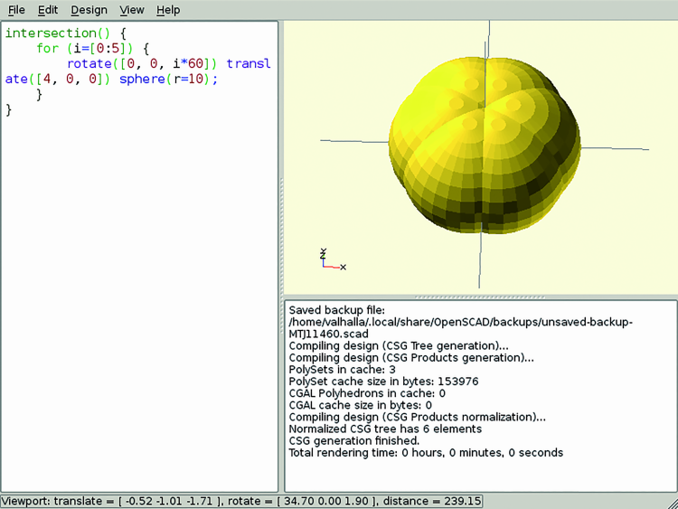
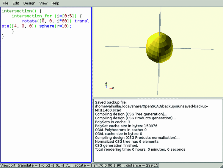
In our example we want to add the board supports and remove the holes for power & usb connectors: in both cases, we use a for loop. In OpenSCAD, “for” loops can work on arrays or on a numerical range: in our case we work on pins and connectors arrays. If we wanted to work on a range, we could use a syntax like:
for (i = [0: 2]) {
echo (i);
}
which will print:
0
1
2
In this example we put all the connectors on one side only. If you have a board with connectors on multiple sides, it can be a good exercise to change connectors to an array of arrays and cycling on two levels.
Again, once you finished and saved the model, you have to execute Design → Compile and Render (CGAL) followed by the export to STL and you will have a file that can 3D printed as you do normally.
If we want to share our model on a site that does not support directly “.scad” or “.stl” file formats, we can also save the image on the preview window: after Compile and Render (CGAL) you can execute the command Design → Export as Image …
Remember that OpenSCAD is a Free and multiplatform software (under GNU GPL) available in the repositories of most Linux distributions and as a free Windows and OSX download from the official website.
From openstore
3DRAG – 3D Printer dual extruder – KIT
Expansion set for printer 3Drag

Related Posts


-
 Arduino ISP (In System Programming) and stand-alone circuits
We use an Arduino to program other ATmega without...
- Posted 12 years ago
-

-

-
 GSM GPS shield for Arduino
Shield for Arduino designed and based on the module...
- Posted 12 years ago
-
 Small Breakout for SIM900 GSM Module
Some post ago we presented a PCB to mount...
- Posted 13 years ago
-
 Join Maker Faire Rome 2024: Innovation Unleashed at Gazometro Ostiense | Calls Now Open!
All Calls Now Open for Maker Faire Rome 2024...
- Posted 2 weeks ago
-
 Building a 3D Digital Clock with Arduino
Project to create a digital clock consisting...
- Posted 4 months ago
-
 Acoustic amplifier – in DIY Kit
This kit creates a microphone amplifier with an output...
- Posted 5 months ago
-
 Creating a controller for Minecraft with realistic body movements using Arduino
Project of a controller that maps body movements...
- Posted 5 months ago
-
