- Building a 3D Digital Clock with ArduinoPosted 4 months ago
- Creating a controller for Minecraft with realistic body movements using ArduinoPosted 5 months ago
- Snowflake with ArduinoPosted 5 months ago
- Holographic Christmas TreePosted 6 months ago
- Segstick: Build Your Own Self-Balancing Vehicle in Just 2 Days with ArduinoPosted 6 months ago
- ZSWatch: An Open-Source Smartwatch Project Based on the Zephyr Operating SystemPosted 7 months ago
- What is IoT and which devices to usePosted 7 months ago
- Maker Faire Rome Unveils Thrilling “Padel Smash Future” Pavilion for Sports EnthusiastsPosted 8 months ago
- Make your curtains smartPosted 8 months ago
- Configuring an ESP8266 for Battery PowerPosted 8 months ago
An intelligent XMAS Lamp to Light up your Christmas!
The Christmas eve is approaching and – even if we’re a bit late on this – we make a Christmas Lamp, capable of emitting light of the same color of the surface it is laid on!
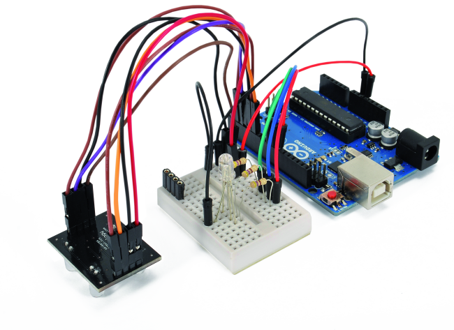
The project can be divided into three “modules”. A “sensor module” able to recognize the color tone of the lamp supporting surface. A “processing module” capable of decoding the output signal from the “sensor” and process it to produce as output “something” capable of driving a “programmable” light source. Last, a “lighting module” capable of reproducing a bright hue from a default input.
For the color recognition module we have opted for the TCS230 “Module with Colors Recognition Sensor” produced by LC Technology Co. Ltd. To reproduce the hue detected by the sensor, the choice is very simple. An RGB LED will be fine in the prototyping stage and opens the way to different choices for the final production, as the RGB led driver can drive a wide range of light sources products, available on the market in a variety of forms, size, power and … price.
The main function of the “processing module” is as you can guess, to apply to the pins that drive each color a PWM signal proportional to the intensity of the corresponding color component detected by the sensor. We just have to choose what to use as a “processing module”. For a first prototype the choice is easy, just reach out on the desk and use the omnipresent Arduino Uno. His vocation is precisely to make quick and easy prototypes… working!
TCS230 Module with Color Recognizing Sensor

The module TCS230 is produced by LC Technology Co., Ltd. (http://www.lctech-inc.com), a company based in Shenzhen, China. This module is nothing but a break-out board with TCS230 onboard sensor, a programmable converter that can convert incoming light into a frequency signal proportional to the intensity of perceived light. The integrated circuit in CMOS technology includes an 8×8 array of photodiodes and a current-to-frequency converter following the block diagram. In the sensor, there are three color filters R, G and B (coincidentally!) and the color components measurement consists of a first measurement of the composed light intensity (no filter) and then of relative intensities of each color (measured by applying the three filters one at a time).


Figure shows the pinout of the integrated circuit while table defines the functions assigned to the individual pins. The TCS230 module pins are one to one corresponding to the IC pins. The diodes on the module are powered in parallel and serve to “illuminate” the field of “vision” of the sensor. The module can be powered by voltages from 2.7V to 5.5V and is therefore compatible with the outputs of microcontrollers either at 3.3V or at 5V.

The converter TCS230 reads the photodiodes that make up the matrix. Depending on the configuration of control pins S2 and S3 the diode matrix filters the red, green, blue or white and outputs at OUT pin a square wave signal with 50% duty cycle and frequency directly proportional to the perceived light (irradiance).

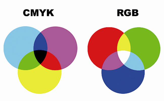
The functioning of the sensor utilizes the fact that the different color nuances can be attributed to a combination of the three basic colors, red, green and blue, in appropriate proportions. When the filter is set for a given predominant color, for example blue, the integrated TCS230 examines only the intensity of the color considered excluding others. In this way it is possible to determine the blue component of the color detected. Same procedure for determining the intensity of the red and green components.

The amplitude of the spectrum of the emitted frequency can be scaled by factors expressed in table properly configuring pins S0 and S1 levels, in order to match the processing capabilities of the microcontroller used. The inputs and outputs can be interfaced to a microcontroller for configuring and reading frequency values, which we will do with our microcontroller.
RGB LED
To reproduce the color tone read by the sensor we will use an RGB LED, at least in our prototype, or an optoelectronic device consisting of three LEDs that respectively emit Red, Blue and Green. There are two types of these components: “common anode” and “common cathode”. In the first, all LEDs have the anode, ie the positive terminal, in common while the three LEDs are controlled individually by driving the cathode terminal of each. In “Common cathode” components the three LEDs share the negative terminal while each individual LED is driven using the anode, which is the positive terminal. A configuration, the latter, more suitable to be used with Arduino Uno. In fact, the LED control uses three analog outputs (DAC) of Arduino Uno, that is able to convert the digital values between 0 and 255 into proportional voltage values between 0 and + 5V
Each hue in the RGB representation with eight bits of precision, is represented by a tern of values in the range 0-255 which reflects the intensity of each color component. For example, the intense red is represented by the configuration (255, 0, 0).
At http://www.rapidtables.com/web/color/RGB_Color.htm you can see a table that shows the correspondence between the color tones and their RGB representation. It is worth noting a peculiarity related to grayscale: who has been involved in image processing knows that the gray tones are expressed by sets of equal RGB values, for example (150, 150, 150). Not being able to reproduce with our LED any shade of gray, we will ensure that in these conditions the LED emits white light. The LED RGB chosen for our prototype is signed 540R2GBC-CC.
The schematics
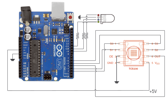
In the scheme we can see the connections between the sensor TCS230, the microcontroller Arduino and LED RGB.

The terminals S0 and S1, which serve to configure the frequency range emitted from the output of the TCS230 sensor are connected to Arduino pins 2 and 3. The outputs S2 and S3 that define whether or which filter to use in the reading of the light intensity are respectively connected to the digital outputs 6 and 5. The output terminal of the TCS230 sensor is connected to input 4 of Arduino. Finally the three terminals of the RGB LEDs are connected to the Arduino PWM outputs 9 (R), 10 (G) and 11 (B). PWM outputs are identified by a “-” on the card serigraphy. We used the three outputs mentioned since they share the same interval of the PWM output frequency. If we chose other pins we would have encountered an abnormal function because pins 5 and 6 have output frequency of 976Hz while the other pin 3, 9, 10 and 11 have output frequency to 488Hz. To avoid surprises and malfunctions difficult to detect is always advisable to read the product description and documentation of the components when dealing with a new project. In our case we connected the terminals of LED RGB to three PWM outputs characterized by the same clock frequency. The three resistors by 470 ohm limit the input current to the output terminals to about 20 mA.
Arduino Uno Code Sketch
The sketch in Listing 1 allows you to manage the logic of our lamp, the process of color recognition and its reproduction as bright hue on LED RGB. Working on the prototype with Arduino we can introduce a set of instructions useful for debugging purposes that later we will eliminate when realizing the final product. In our case we will use the Serial Monitor to display the readings and the results of calculations performed. The constant isPresentTolerance allows setting a threshold value to determine if the lamp is put on a surface or not. We used the expedient of performing a reading with the LED switched on and one with the LED off. To turn the LEDs on and off we will configure properly the pins S0 and S1. If lamp is placed on a surface we will have two very different values, while if the lamp is “suspended”, the ambient light will reach the sensor in any case giving so two close values read. If the lamp is laying on a surface, we will measure both the total intensity of the reflected light and the relative intensities of the individual color components, applying to each reading the appropriate filters configuration through the TCS230 pin S2 and S3. The relative intensity of each component is calculated in relation to the total color intensity, read without the presence of any filter. To read the emitted frequency in correspondence of the application of each filter it is used the instruction “pulsein”, which reads the pulse length on a specific pin. The instruction can be configured to read the pulse duration in LOW level or HIGH level, in our case LOW. In this case, the instruction waits until the pin level takes the value LOW, then starts measuring time until the level returns HIGH, interrupting the measurement. The result of the reading is in microseconds. The instruction is:
pulseIn(pin, value, timeout)
where:
pin: where you want to read the pulse (int)
value: level HIGH o LOW, when you want to read the value (int)
timeout (optional): time window within you are expecting the pulse. The default is 1 sec (unsigned long). It there is a timeout and no pulse read, it returns 0.
The instruction “pulsein” works for pulses lasting between 10 microseconds and three minutes though for very long pulses it can cause reading errors. The logic for the color recognition requires a first reading in the absence of filters, a condition which is achieved by setting pins S2 and S3 respectively high and low. It is read the value present on the OUT pin. Sequentially will be set filters corresponding to the three basic colors and read the values of the relative intensities, in relation to the overall value of the intensity (intensity Total Value / Value Color Intensity). For comparison and selection of the higher relative intensity is then calculated the predominant color to which is assigned the PWM driver value 255. The values to drive PWM signal for other colors are calculated on the proportion between the value read for the color detected and the value of the predominant color referenced to 255. As a last step, the PWM values so calculated are used to drive the respective pins connected to the RGB LED terminals.
/*

Sketch Christmas Lamp

*/

int S0 = 2;    // output frequency control pin

int S1 = 3;    // input frequency control pin

int S2 = 6;    // pin color filter control

int S3 = 5;    // pin color filter control

int taosOutPin = 4;   // pin output for PWM

int LED = 13;  // pinD

int R = 9;     // PWM red

int G = 10;    // PWM green

int B = 11;    // PWM blue

double Coeff = 0;

int Ro = 0;    // pin E

int Go = 0;    // pin E

int Bo = 0;    //  pin E


void setup() {

TCS230setup();

Serial.begin(115200);

Serial.print("\n\n\nready\n\n\n");

pinMode(R,OUTPUT); //S2 pinE

pinMode(G,OUTPUT); //S2 pinE

pinMode(B,OUTPUT); //S2 pinE

delay(100);

}

void loop() {

Serial.print(detectColor(taosOutPin)); // serial debug

Serial.print("\n\n\n");

delay(1000);

}

int detectColor(int taosOutPin){

// surface detection

double isPresentTolerance = 5;

double isPresent = colorRead(taosOutPin,0,0)/colorRead(taosOutPin,0,1);

Serial.print("isPresent:");

Serial.println(isPresent,2);

Serial.print("valore isPresentTolerance:");

Serial.println(isPresentTolerance,2);

if(isPresent < isPresentTolerance){

Serial.println("nessuna superficie rilevata");

return 0;

}

  double red,blue,green;

  // light intensity detection no filters

  double white = colorRead(taosOutPin,0,1);

  // red

  red = white/colorRead(taosOutPin,1,1);

  // blue

  blue = white/colorRead(taosOutPin,2,1);

  // green

green = white/colorRead(taosOutPin,3,1);

Serial.print("red");

Serial.println(red);

Serial.print("blue");

Serial.println(blue);

Serial.print("green");

Serial.println(green);


if(red > blue && red > green){

     Coeff = 255 / red;

     Ro = 255;

     Go = green * Coeff;

     Bo = blue * Coeff;

     LED_RGB(Ro, Go, Bo);

     return 1;

  }

  if(blue > green && blue > red){

     Coeff = 255 / blue;

     Bo = 255;

     Go = green * Coeff;

     Ro = red * Coeff;

     LED_RGB(Ro, Go, Bo);

    return 2;

  }

  if(green > blue && green > red){

     Coeff = 255 / green;

     Go = 255;

     Ro = red * Coeff;

     Bo = blue * Coeff;

     LED_RGB(Ro, Go, Bo);

     return 3;

  }

}


double colorRead(int taosOutPin, int color, boolean LEDstate){

  //make sure that the pin is set to input


  pinMode(taosOutPin, INPUT);


  taosMode(1);

  int sensorDelay = 3;

  //set pins to trigger filters

  if(color == 0){// bianco (no filtri)

     digitalWrite(S3, LOW); //S3

     digitalWrite(S2, HIGH); //S2

  // Serial.print(" w");

  }else if(color == 1){// red filter

     digitalWrite(S3, LOW); //S3

     digitalWrite(S2, LOW); //S2

  // Serial.print(" r");

  }else if(color == 2){// blue filter

     digitalWrite(S3, HIGH); //S3

     digitalWrite(S2, LOW); //S2

  // Serial.print(" b");

  }else if(color == 3){// green filter

     digitalWrite(S3, HIGH); //S3

     digitalWrite(S2, HIGH); //S2

  // Serial.print(" g");

  }

  double readPulse;

  if(LEDstate == 0){

    taosMode(0);

//      digitalWrite(LED, LOW);

  }

  if(LEDstate == 1){

  taosMode(1);

//      digitalWrite(LED, HIGH);

  }

  delay(sensorDelay);

  readPulse = pulseIn(taosOutPin, LOW, 80000);

  // pulse timeout read setting

  if(readPulse < .1){

     readPulse = 80000;

  }

  // turn off sensor led

  taosMode(0);

  return readPulse;

}

// manages the frequency output mode TaosMode(0);

// sero, sensor quiet


void taosMode(int mode){

  if(mode == 0){

  //power OFF

     digitalWrite(LED, LOW);

     digitalWrite(S0, LOW); //S0

     digitalWrite(S1, LOW); //S1

  // Serial.println("mOFFm");

  }else if(mode == 1){

     // frequenza 1:1

     digitalWrite(S0, HIGH); //S0

     digitalWrite(S1, HIGH); //S1

  // Serial.println("m1:1m");

  }else if(mode == 2){

  // frequenza 1:5

     digitalWrite(S0, HIGH); //S0

     digitalWrite(S1, LOW); //S1

  //Serial.println("m1:5m");

  }else if(mode == 3){

  // frequenza 1:50

     digitalWrite(S0, LOW); //S0

     digitalWrite(S1, HIGH); //S1

  //Serial.println("m1:50m");

  }

  return;

}


void LED_RGB(int Rx, int Gx, int Bx){

  analogWrite(R, Rx);

  analogWrite(G, Gx);

  analogWrite(B, Bx);

  return;

}


void TCS230setup(){

  // init pin frequency management

  pinMode(LED,OUTPUT);

  // color filter management pin

  pinMode(S2,OUTPUT); //S2

  pinMode(S3,OUTPUT); //s3

  // output pin light-frequency conversion

  pinMode(taosOutPin, INPUT);

  // pin to select ouput mode

  pinMode(S0,OUTPUT); //S0 pinB

  pinMode(S1,OUTPUT); //S1 pinA

  return;

}
To run it, open the Arduino IDE and copy the sketch in the editor IDE. Connect Arduino Uno to the PC with the USB cable, set the COM port and the Board as shown above. Compile and upload the sketch into the microcontroller. Open the Serial Monitor. Place the sensor on objects or paper sheets of different colors and … enjoy yourself testing it. Now let us see if our 3D printer has finished printing the lamp. Nice Christmas tree, just assemble “summarily” the whole prototype and go around collecting comments!

From the Store
Arduino UNO
TCS230

Related Posts


-
 Arduino ISP (In System Programming) and stand-alone circuits
We use an Arduino to program other ATmega without...
- Posted 12 years ago
-

-

-
 GSM GPS shield for Arduino
Shield for Arduino designed and based on the module...
- Posted 12 years ago
-
 Small Breakout for SIM900 GSM Module
Some post ago we presented a PCB to mount...
- Posted 13 years ago
-
 Join Maker Faire Rome 2024: Innovation Unleashed at Gazometro Ostiense | Calls Now Open!
All Calls Now Open for Maker Faire Rome 2024...
- Posted 2 weeks ago
-
 Building a 3D Digital Clock with Arduino
Project to create a digital clock consisting...
- Posted 4 months ago
-
 Acoustic amplifier – in DIY Kit
This kit creates a microphone amplifier with an output...
- Posted 5 months ago
-
 Creating a controller for Minecraft with realistic body movements using Arduino
Project of a controller that maps body movements...
- Posted 5 months ago
-

2 Comments