- Building a 3D Digital Clock with ArduinoPosted 4 months ago
- Creating a controller for Minecraft with realistic body movements using ArduinoPosted 5 months ago
- Snowflake with ArduinoPosted 5 months ago
- Holographic Christmas TreePosted 6 months ago
- Segstick: Build Your Own Self-Balancing Vehicle in Just 2 Days with ArduinoPosted 6 months ago
- ZSWatch: An Open-Source Smartwatch Project Based on the Zephyr Operating SystemPosted 7 months ago
- What is IoT and which devices to usePosted 7 months ago
- Maker Faire Rome Unveils Thrilling “Padel Smash Future” Pavilion for Sports EnthusiastsPosted 8 months ago
- Make your curtains smartPosted 8 months ago
- Configuring an ESP8266 for Battery PowerPosted 8 months ago
An Arduino powered, easily extendable GPS Datalogger

By coupling a standard NMEA GPS receiver and an Arduino board we created a super simple and effective Arduino GPS logger. This device allows you to trace the route taken by a person or vehicle (or any other moving object) by simply doing a periodic caching of location points coming from the GPS unit. As the logger saves the list of records (containing data on recorded positions) on a microSD memory card, you can then move the data onto your computer and keep track of your trip. You can use tracked data to help project such as OpenStreetMap to grow and include new areas (www.openstreetmap.org).
An intelligent logger
Being experienced users of other loggers in the market, we realized that one of the most annoying things is to forget to turn it off once you get to destination. This means consuming memory because the device continuously saves almost the same position. For this reason we decided to implement a system that is able to stop recording when the logger is still. This feature was obtained thanks to an accelerometer which, in addition to stop saving data when the tracker has stopped, also allows to turn off the GPS module to reduce consumption, which is useful, since this kind of systems normally feeds on batteries.
Hardware

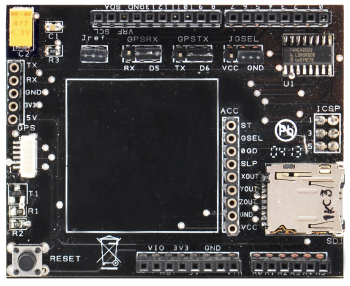
As said, the logger consists of a shield, on which there are mainly the GPS receiver, the SD-Card reader and the accelerometer, in addition to an Arduino UNO board. The GPS receiver is connected through two connectors (each one alternative to the other) then you can actually place it out of the shield. This can be useful if you plan to mount more shields above the circuit, which inevitably disturb the reception of satellites signals.
Let’s look at the circuit of the shield, which, by virtue of its reduced power consumption, it is powered directly from the Arduino. Our measures, when powering it with the Arduino 5V, indicate a consumption of around 35 mA, with the GPS on, reduced to about 5 mA by turning it off via pin 7.
Moreover, we have the 40 mA of the Arduino ONE, for a total of 75 mA in LOG mode (ie during the acquisition and recording of coordinates) and 45 mA in standby mode.
The main part of the shield is obviously composed of the GlobalSat GPS EM406 module, with a built-in antenna (on top of it) which communicates with the Arduino via the NMEA 0183 protocol. Communication is serial (4800 bps) and uses the TX and RX lines at TTL level. This signal is available on the serial and GPS connector through GPSRX and GPSTX jumpers and can be routed to pins 0 and 1 (RX and TX of the integrated serial port) of the Arduino. Alternatively you can use pins 5 and 6. In this regard it should be noted that lines 0 and 1 constitute Arduino’s physical UART: if this is not available because it is already used by other applications (for example because you mounted another shield), you can, via the SoftwareSerial library, set your board to handle 5 and 6 lines as a virtual UART.
The GPS module is activated by setting pin 7 to logic low: from that moment it will cyclically transmit NMEA strings on the serial port until it will be disabled by setting it to high.
As for the microSD slot, the shield includes 74HC4050D level converter to allow communication via the SPI at 0/3, 3V levels (in fact the SD card and micro SD use the Serial Peripheral Interface bus for external communications). The signals are connected to the ICSP header so as to allow compatibility with the Arduino MEGA.
You can access a FAT16 or FAT32 formatted microSD, by using the SD Arduino library available in the development environment, taking care of using SD.begin(4) to configure the Chip Select different from the standard.

The accelerometer, dubbed ACC in the wiring diagram: it’s the MMA7361, a three axes one produced by Freescale: for this we use the version produced by Sparkfun, already mounted on a board showing 9-pins single-in-line with a 2.54mm pitch. This module is powered with 3.3V by the Arduino board by using the the 3.3V line and GND, which on the MMA7361 reach the pins, respectively, VCC and GND. The accelerometer outputs a triple analog signal concerning the detected acceleration on each of the axes, and the signals are available at pin 4 for the X axis, 3 for the Y axis and 2 for the Z axis.
By the JREF jumper is possible to connect Arduino’s VREF to 3.3 V, so that the 1.65 V accelerometer output, that corresponds to no acceleration (0g), roughly coincides with the 512 value at the output of the A/D 10-bit Arduino converter, ie in the middle of the excursion (the A / D ranges from 0 to 1024).
JGSEL jumper allows you to select one of two modes of operation of the accelerometer: when connected to GND it will have a full scale of 1.5 g and a resolution of 800 mV/g, corresponding to a analogRead value of about 248 for g; when connected to VCC the full scale goes to 6 g and the resolution to 206 mV/g, corresponding to sampling about 64 per g.
The default configuration of our logger provides that the central jumpers of the shield, ie GPSRX and GPSTX, are always closed on right pins (ie, D5 and D6, respectively), while the JGSEL jumper related to the accelerometer, is closed to GND. In addition JREF jumper must be closed as well.
The firmware
For the sake of simplicity, we decided to save NMEA strings received on the memory of the GPS module; this also helps saving space compared to most popular formats such as GPX and KML, which however can be obtained from raw data through special programs.
SoftwareSerial will help us handle the communication with the GPS module and the board,if the microSD card is not present, the GPS data will be sent on the Arduino serial, so it can be directly sent to a computer for debugging and advanced applications.
The accelerometer controls the movement approximately every second, if a movement is perceived (in any direction) the logger stays active or it’s activated. On the other hand if the movements stay below a certain threshold (M_THRESH) for one minute (the time period is configurable via the STOP value, in milliseconds) the GPS is turned off.
The values in the program sketch have been empirically checked to provide acceptable results in typical usage scenarios.
For your convenience, when we stop to save the data in the debug phase, we write a a proprietary PXXXX string in the NMEA file, this will be properly ignored by programs. The same string is used to report any SoftwareSerial overflow, which could be a sign of problems.
The SD file (data.log in our example) is frequently closed, so that at any time it is possible to cut off the power, move the microSD into a card reader get the tracking done.
With an easy customization, the logger could integrate some environmental sensors and add information to our travel log as to obtain geo-referenced data.
In future posts we will discuss how to interpret the NMEA Arduino sentences so that you can create more complex projects than just saving data.
#include <SD.h>

#include <SoftwareSerial.h>

/* ****** Settings ****** */
char log_filename[13] = "data.log"; // keep this FAT friendly
// how long should we wait when not moving before we stop logging
#define STOP 60000
/* ****** End of user settings ****** */

#define PIN_GPS_ENABLE 7
SoftwareSerial gpsSerial(5,6);

#define PIN_SD_SS 10
File log_file;
boolean sd_available = false;

boolean moving = true;
unsigned long last_move = 0;
#define ZERO_X 512
#define ZERO_Y 512
#define ZERO_Z 512
#define M_THRESH 60000
#define PIN_X 4
#define PIN_Y 3
#define PIN_Z 2

void setup() {
   Serial.begin(9600);

   //GPS setup
   gpsSerial.begin(4800);
   pinMode(PIN_GPS_ENABLE,OUTPUT);
   digitalWrite(PIN_GPS_ENABLE,HIGH);

   //SD setup
   pinMode(PIN_SD_SS,OUTPUT);
   pinMode(10,OUTPUT);
   start_sd();

   start_gps();
}

void loop() {
   if(moving) {
       if(sd_available) {
           log_file = SD.open(log_filename,FILE_WRITE);
           if(!log_file) {
               sd_available = false;
           }
       }
       if(gpsSerial.overflow()) {
           if(sd_available) {
               log_file.write("\r\n$PXXXX,SoftwareSerial overflow!!!");
           } else {
               Serial.println("\r\n$PXXXX,SoftwareSerial overflow!!!");
           }
       }
       while(gpsSerial.available()) {
           int r = gpsSerial.read();
           if(sd_available) {
               log_file.write(r);
           } else {
               Serial.write(r);
           }
       }
       check_movement();
       log_file.close();
   } else {
       delay(1000);
       check_movement();
   }
}

void start_gps() {
   gpsSerial.listen();
   digitalWrite(PIN_GPS_ENABLE,LOW);
}

void stop_gps() {
   digitalWrite(PIN_GPS_ENABLE,HIGH);
}

void start_sd() {
   if (!SD.begin(PIN_SD_SS)) {
       Serial.println("Card failed, or not present");
   } else {
       log_file = SD.open(log_filename,FILE_WRITE);
       if (log_file) {
           log_file.close();
           sd_available = true;
       } else {
           Serial.print("Can't open file <");
           Serial.print(log_filename);
           Serial.println("> for writing.");
       }
   }
}

void check_movement() {
   int x = analogRead(PIN_X) - ZERO_X;
   int y = analogRead(PIN_Y) - ZERO_Y;
   int z = analogRead(PIN_Z) - ZERO_Z;
   long acc = (long)x*x + (long)y*y + (long)z*z;
   if (acc > M_THRESH) {
       last_move = millis();
       if (! moving) {
           start_gps();
           start_sd();
           // Ignore data that has overflowed
           gpsSerial.overflow();
       }
       moving = true;
   } else {
       if (moving) {
           unsigned long now = millis();
           // TODO: check for the overflow condition of millis
           // (or reboot the arduino every 49 days :) )
           if (now-last_move > STOP) {
               moving = false;
               stop_gps();
               if(sd_available) {
                   log_file.write("\r\n$PXXXX,Device is idle, stop logging\r\n");
               } else {
                   Serial.println("\r\n$PXXXX,Device is idle, stop logging\r\n");
               }
           }
       }
   }
}
Manage files NMEA
NMEA files saved in our logger can be directly read by a limited number of programs. Fortunately, GPSBabel, a free program, allows you to convert to and from most of the formats used by GPS systems. GPSBabel for Windows and OS X can be downloaded from the official website (https://www.gpsbabel.org/). Linux users can find it in the repository of their distribution. Using it is simple: just select the input format (in our case NMEA), the name of the file to be read (data.log on the microSD), the format to be generated (eg GPX for most of the programs or KML for Google Earth) and the name of the output file.
GPSBabel offers innumerable options to complete the conversion, but the defaults are generally suitable for most uses.
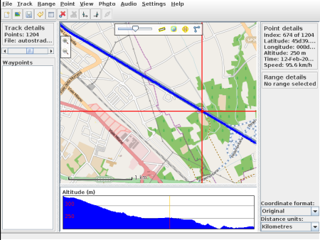
Another program that can be useful is GpsPrune, this free and multi-platform (Java), program enables you to convert and manipulate GPS tracks using as background the Free maps from OpenStreetMap project, and directly supports the NMEA format.
GpsPrune can be downloaded from the official website and http://activityworkshop.net/software/gpsprune/ and is as well available for most of the Linux distributions via the repositories.
Note that to open the files you will need to rename them with .nmea extension.
In the Store

Related Posts


9 Comments
Leave a Reply
-
 Arduino ISP (In System Programming) and stand-alone circuits
We use an Arduino to program other ATmega without...
- Posted 12 years ago
-

-

-
 GSM GPS shield for Arduino
Shield for Arduino designed and based on the module...
- Posted 12 years ago
-
 Small Breakout for SIM900 GSM Module
Some post ago we presented a PCB to mount...
- Posted 13 years ago
-
 Join Maker Faire Rome 2024: Innovation Unleashed at Gazometro Ostiense | Calls Now Open!
All Calls Now Open for Maker Faire Rome 2024...
- Posted 2 weeks ago
-
 Building a 3D Digital Clock with Arduino
Project to create a digital clock consisting...
- Posted 4 months ago
-
 Acoustic amplifier – in DIY Kit
This kit creates a microphone amplifier with an output...
- Posted 5 months ago
-
 Creating a controller for Minecraft with realistic body movements using Arduino
Project of a controller that maps body movements...
- Posted 5 months ago
-

Pingback: An Arduino powerer, easily extendable GPS Datal...
Pingback: An Arduino powered, easily extendable GPS Datal...
Pingback: An Arduino powerer, easily extendable GPS Datal...
Pingback: An Arduino powered, easily extendable GPS Datalogger | ElectronicsEU.com