
We will equip Arduino with wireless connectivity basing on MRF24J4 module by Microchip. As a sample application, we will remotely control a relay, operated by a floating input, and we will virtualize the Arduino USB serial port.
The MRF24J40MA radio module is manufactured by Microchip, that also provides useful and complete software libraries (identified as MiApp) for module management (creation of a complex wireless network, network identification, device addressing, sending and receiving data, etc. …). Clearly, Microchip provides those libraries free of charge only if they are compiled with MPLAB (Microchip C compiler and development environment) and executed in a Microchip CPU (PIC microcontrollers).
On other hands, Microchip provides the data-sheet of all its devices (MRF24J40MA included) and the complete knowledge base for their management. So, nothing prevents you from deeply study the data-sheet and, starting from zero, write down your own libraries for the CPU and development environment you want to use.
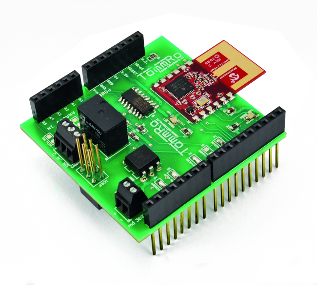
From these considerations, we decided to start the project that we are presenting on these pages whose ultimate goal is to use the wireless module MRF24J40MA with an Arduino hardware platform. The additional shield we developed, to have the radio module and all its components working properly, has also an output relay and an opto-coupled input. The rationale behind this choice is to equip the shield not only with the radio part but also with at least a pair of input / output so that it could be more than enough for simple applications.
Regarding our newly developed software libraries for Arduino, those cannot fully cover all of the features offered by the Microchip proprietary libraries (that allow you to create different types of networks, broadcast communications, etc ….). The operations already available are enough for the basic management of a WiFi network: module initialization, setting of network PAN ID, set the node network address, transmit and receive data. Because of these differences between Arduino and Microchip libraries, some features have been simplified. In particular, we have removed the distinction between Coordinator and End Device node but hierarchically all nodes have the same level and offer the same functionality. Maybe you lose some application optimization but surely, you have huge advantages (which, in our opinion, largely cover the disadvantages) from the point of view of simplicity and ease of use.
WiFi Hardware Chip
MRF24J40 is a RF transceiver, compatible with 2.4GHz IEEE 802.15.4 standard.
For our applications, we will use the full version of the module (MRF24J40MA) that besides the transceiver integrates also a tuned antenna, quartz and other external components required for WiFi communication. It has a mechanical strip shape, 2,54mm step and has already passed all wireless required certifications.
To interface with an external MCU it has an SPI port, interrupt, wake and reset pins; there are also pins for power feed.
The access to the various radio functions is through the read / write of a long series of internal chip registers (for details, please consult the full product description). Our libraries shall manage these registers, hiding at Arduino application level the implementation details but offering the general function calls for configuration and communication.
Arduino MRF24J40 Library
The MRF24J40 libraries for Arduino offer some basic functions of wireless network configuration and communication. They have not all the features of Microchip MiApp but there are all the necessary functions to set up a WiFi network, to address nodes and to allow direct data exchange between them.
The library provides an object called Mrf24j for the complete WiFi stack management. The object constructor gets as input the number of Arduino pin to be used for reset, chip select and radio module interrupt (the SPI port is the default, ie pins 11, 12 and 13 for the Arduino Uno).
There is a reset function that, through the reset pin as defined above, resets the chip (best practice is to reset hardware every time the software starts) and a Init (to be called after the reset) that initializes the SPI port and the registers of the radio module.
To work properly and to exchange messages, every node needs to specify which WiFi network (PAN ID, clearly the same for all) they belong and which is its unique network address. To set the PAN ID we have to use two functions (void set_pan (word PANID) and word get_pan (void)) that respectively write and read the PAN ID chosen.
Instead to configure nodes addresses, we will use void address16_write (word address16) and word address16_read (void) (since the variable is a 16-bit word, we cannot have more than 256 nodes in the network).
Other config functions that may be useful are:
- void set_channel (byte channel) that allows you to specify what radio channel to be used;
- void set_promiscuous (boolean enabled) that allows you to configure whether to use normal or promiscuous rx (i.e. if you want to receive any packets from the channel);
- void rx_enable(void) and void rx_disable (void) that respectively enable or disable the receiving section;
- void set_palna (boolean enabled) that allows you to enable the external controller PA / LNA;
- void set_bufferPHY (boolean bp), which allows to enable the receival of both user data and physical communication payload.
Let us check how the communication works and the functions involved. The first thing to say is that the whole mechanism is implemented in a special way using Arduino CPU interrupt. This implementation is perhaps a bit more difficult than usual but allows you to manage everything more efficiently involving the Arduino CPU only when necessary.
The radio chip has a pin that sends an interrupt to the CPU to indicate that it has data ready; The Arduino software must be written to handle the interrupt indicating what to do in these cases. As we shall see later by analyzing the source code, we use the Arduino attachInterrupt to indicate which function must be executed when a “change interrupt” occurs from the MRF radio interrupt pin.
The software library contains the function void interrupt_handler(void) called directly by the specified interrupt handler. The handler reads all the data from the radio module and makes it “available” again to receive further information.
Other things to define are the two functions that respectively receive and transmit data. Once you have defined these functions, the MRF24J40 library offers the methods void check_flags (void (* rx_handler) (void), void (* tx_handler) (void)) that must be called cyclically (typically in the method loop ()) to manage properly the defined handlers, avoiding overlapping between Rx and Tx.
Finally, the real functions for transmitting and receiving are respectively void send16 (word dest16, char * data) that needs parameters like network address of the destination node and the pointer to the data buffer to be transmitted and rx_info_t * get_rxinfo (void), which returns a pointer to a structure type rx_info_t specially defined to encapsulate all the information received.
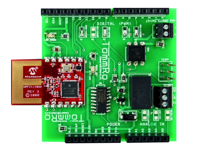
Electrical Wiring
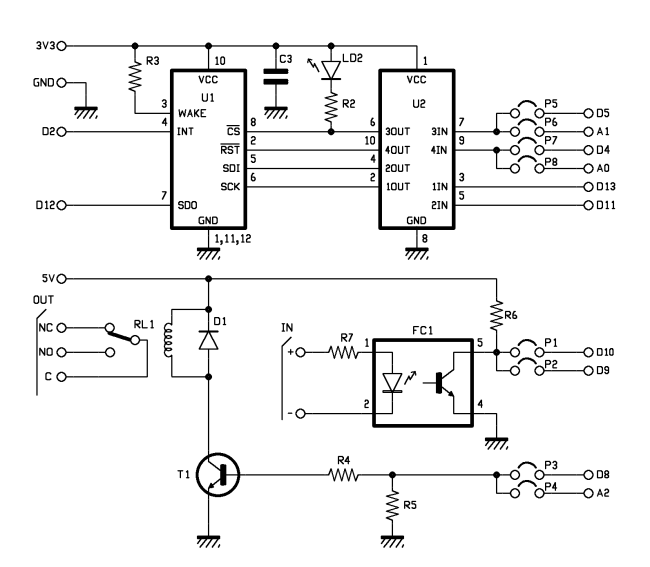
The hardware is based mainly on the WiFi module MRF24J40MA (chip U1). The radio chip needs to be managed by a main CPU through the SPI port, to receive commands and send responses. The SPI port is located on pins 5, 6, 7 and must be connected to Arduino SPI pins (SCK, MISO and MOSI).
The radio module requires a power supply of 3.3V, while the Arduino digital port works at +5V, so you cannot make a direct connection but you must match the right voltage levels. Our choice fell on an integrated circuit designed for this purpose, the chip 74HC4050D (U2 chip in the diagram). Since all the connections between Arduino and MRF24J40MA need different voltages, we will convert all of them through the 74HC4050D.
In addition to the SPI port, the radio chip also provides the Wake, Interrupt, Reset and Chip Select pins. The Wake pin is directly connected to the positive voltage level because we choose to keep always the radio on.
The Interrupt pin is connected to Arduino D2 digital port; this is because Arduino can control the pin D2 via an interrupt and, as we can see by analyzing the sketch source code, this mechanism allows a more efficient resources management.
The other two pins (Reset and Chip Select) can be operated from any other Arduino digital port; to leave a certain amount of freedom of choice (in order to be ready for further development or additional shields), we have prepared two solder bridges to each pin; by soldering one of them, you can make your own choice.
Finishing the radio module analysis, we note the 100nF capacitor C3 connected to the WiFi chip power pin (as required by the data-sheet) and the presence of a LED (green LED in the diagram) connected to the Chip Select pin of MRF24J40MA itself (in order to get the visual indication of the presence of the communication).
With regard to the communication part of the electric scheme, the analysis is done; however, we choose not to implement a simple transmission shield but equip it with at least a minimum set of input and output. In particular, we have provided a photo-coupled input (based on the photo-coupler 4N25) and an output relay (RL1 relay driven by BJT T1 stage). Also for these I / O, we decided to leave freedom of choice about which Arduino port to be used (always using the technique of the two solder bridges).

Arduino Sketch
/*************************************************************************************************

* Title:       Mrf24j40ShieldExample01

* Autors:       Ingg. Tommaso Giusto e Alessandro Giusto

* Date:         26/06/2014

* Email:        tommro@libero.it

*************************************************************************************************/


/*************************************************************************************************

* Library include

*************************************************************************************************/

*/

#include <SPI.h>

#include <mrf24j.h>


/*************************************************************************************************

* Definition pin I/O Arduino

*************************************************************************************************/

// Pin reset radio module

const int pinResetMRF = 4;

// Pin chip select radio module

const int pinCSMRF = 5;

// Pin interrupt radio module

const int pinIntMRF = 2;

// Pin relays MRF shield

const int pinShieldRele = 8;

// Pin input MRF shield

const int pinShieldInput = 10;


// PAN ID wireless

const word PANWireless = 0x1235;


// this node address

const word thisNodeAddress = 0x6001;

//const word thisNodeAddress = 0x6002;


// destination node wireless

const word destNodeAddress = 0x6002;

//const word destNodeAddress = 0x6001;


/*************************************************************************************************

* Variables

*************************************************************************************************/


// object Mrf24j shield

Mrf24j mrfShield(pinResetMRF, pinCSMRF, pinIntMRF);


// last state of input

int lastStatoInput;


/*************************************************************************************************

* source code

*************************************************************************************************/


// board init

void setup() {

// init  I/O

pinMode(pinShieldRele, OUTPUT);

pinMode(pinShieldInput, INPUT);

// relay disable

digitalWrite(pinShieldRele, LOW);

// read current input state

lastStatoInput = LOW;


// init serial port

Serial.begin(9600);


// Reset Mrf24j shield

mrfShield.reset();

// init Mrf24j shield

mrfShield.init();


// set PAN ID

mrfShield.set_pan(PANWireless);

// set sender node address

mrfShield.address16_write(thisNodeAddress);


// uncomment if you want to receive any packet on this channel

//mrfShield.set_promiscuous(true);


// uncomment if you want to enable PA/LNA external control

//mrfShield.set_palna(true);


// uncomment if you want to buffer all PHY Payload

//mrfShield.set_bufferPHY(true);


// attach interrupt handler function when i receive a “change” interrupt

// 0 -> matches Arduino pin 2 (INT0 for Arduino ATmega8/168/328)

attachInterrupt(0, MRFInterruptRoutine, CHANGE);

interrupts();

}


// function to manage MRF interrupt

void MRFInterruptRoutine() {

//sends control to interrupt routine on object Mrf24j shield

mrfShield.interrupt_handler();

}


// main program

void loop() {

int statoInput;

unsigned long currentMillis;

char serialBuffer[105];

int index;

int flag;


// call the handler Rx/Tx

mrfShield.check_flags(&handleRx, &handleTx);


// read input state

statoInput = digitalRead(pinShieldInput);


// if input state is changed:

if (statoInput != lastStatoInput) {

// sends the state (communication protocol)

if (statoInput == HIGH)

mrfShield.send16(destNodeAddress, "INPUT0");

else

mrfShield.send16(destNodeAddress, "INPUT1");


// update last input state

lastStatoInput = statoInput;

}


// if i received data on serial input

if (Serial.available() > 0) {

// Init command buffer

serialBuffer[0] = 'S';

serialBuffer[1] = 'E';

serialBuffer[2] = 'R';

serialBuffer[3] = 'I';

serialBuffer[4] = 'A';

index = 5;

// store the received chars

for (;;) {

// if new char available

if (Serial.available() > 0) {

// queue the char

serialBuffer[index] = (char) (Serial.read());

index++;

// flag the received char

flag = 0;

}

// if new char not available

else {

// if i didn’t receive a new char

if (flag == 1)

// end cycle to store received chars

break;


// set “char not received” flag

flag = 1;

// wait to receive next char

delay(5);

}

}

// add end of string

serialBuffer[index] = (char) ('\0');

// send command

mrfShield.send16(destNodeAddress, serialBuffer);

}

}


// Handler executed when radio receives data

void handleRx() {

int i;


// if the command is valid

if (mrfShield.rx_datalength() > 5) {

// if received an INPUT command

if ((mrfShield.get_rxinfo()->rx_data[0] == 'I') &&

(mrfShield.get_rxinfo()->rx_data[1] == 'N') &&

(mrfShield.get_rxinfo()->rx_data[2] == 'P') &&

(mrfShield.get_rxinfo()->rx_data[3] == 'U') &&

(mrfShield.get_rxinfo()->rx_data[4] == 'T')) {

// set relay

if (mrfShield.get_rxinfo()->rx_data[5] == '0')

digitalWrite(pinShieldRele, LOW);

else

digitalWrite(pinShieldRele, HIGH);

}

// if received command SERIA

else if ((mrfShield.get_rxinfo()->rx_data[0] == 'S') &&

(mrfShield.get_rxinfo()->rx_data[1] == 'E') &&

(mrfShield.get_rxinfo()->rx_data[2] == 'R') &&

(mrfShield.get_rxinfo()->rx_data[3] == 'I') &&

(mrfShield.get_rxinfo()->rx_data[4] == 'A')) {

// send data on the serial interface

for (int i = 5; i < mrfShield.rx_datalength(); i++)

Serial.write(mrfShield.get_rxinfo()->rx_data[i]);

}

}

}

// Handler to transmit data on radio

void handleTx() {

}
We have previously analyzed the libraries for MRF24J40; it is now easier to go through the sketch sample code.
The purpose of the example is to show how to implement a wireless network among different nodes (each identified by a unique address) and to allow the exchange of messages. As example, we decided to “pair” two specific nodes and send from a card to another all characters received on the serial port and vice versa. In addition, there is a sort of “remote” I / O, in the sense that the output of a card mirrors the input of the other and vice versa.
Even having two separate boards, the source code to be loaded on both is the same: the only thing to keep in mind is that the boards should have different network addresses and the network address of a node must be the recipient of the other and vice versa.
Let us look at the code: in the very first lines, we include the necessary libraries (SPI and mrf24j respectively for SPI port and the radio module); then we define the connections between Arduino and MRF24J40MA pins and those used for hardware I/O (to Reset we will use D4; for Chip Select pin D5; for the Interrupt, as described earlier, we are “obliged” to use D2 while for the relay output pin D8 and D10 for the photo-coupled input).
In the following lines, we define the WiFi network PAN ID (const word PANWireless = 0x1235); the node address (const word thisNodeAddress = 0x6001) and the recipient node address (const word destNodeAddress = 0x6002).
Then we define the object to manage all the radio module functions (Mrf24j mrfShield(pinResetMRF, pinCSMRF, pinIntMRF)): as you can see, during the object creation it is necessary to state the pins used to manage the MRF24J40MA.
Before the setup function, we define a variable (int lastStatoInput) that we will use to trace the status of the opto-coupled input; then in the setup function we set that the relay pin is an output, the pin for the ingress is an input and we initialize the serial port with Baud rate to 9600.
Then we reset and initialize the object for the radio communication (instructions mrfShield.reset() and mrfShield.init()).
After that we write on the radio module the PAN ID (mrfShield.set_pan(PANWireless)) and the node address (mrfShield.address16_write(thisNodeAddress)).
Last thing missing, is the interrupt setting: with the instruction attachInterrupt(0, MRFInterruptRoutine, CHANGE) we connect the function that must be executed when the pin MRF Int rises the interrupt. Specifically, 0 corresponds to Arduino pin 2 (INT0 for Arduino ATmega8/168/328); MRFInterruptRoutine is our interrupt routine (will check it later) and finally CHANGE indicates the interrupt request type. Just below we define our interrupt routine (function void MRFInterruptRoutine()) where we simply recall the interrupt routine of Mrf24j shield object (mrfShield.interrupt_handler()).
At this point, we enter the main program (function void loop ()): first, as required by the library for the radio chip, we call the function mrfShield.check_flags (&handleRx, &handleTx) that manages both receive and transmit handlers (handleRx and handleTx functions will be defined later in the code).
Then we read the status of the input and, if changed, we send the current status on the radio (mrfShield.send16(destNodeAddress,”INPUT0″) in case of input “low”). We check if data are present on the serial port and, if so, read them and always with the same command, we send them to the destination node.
Now, the loop function is finished; let us see the two receive and transmit handlers. The first is to receive data (function void handleRx ()) and it will be called only in case of successful reception from the radio. In here, the first thing we verify is that the data is valid according to the protocol chosen by us (if(mrfShield.rx_datalength ()> 5)), just checking if we have received at least 5 bytes (the minimum number that the protocol requires for a valid command).
If so, we read the data from the radio (through mrfShield.get_rxinfo () we access the structure that contains the data and with mrfShield.get_rxinfo () -> rx_data [] we access to the individual bytes from receiver buffer; other useful functions are mrf.get_rxinfo () -> LQI and mrf.get_rxinfo () -> rssi containing two indices on the quality of the radio signal), we verify that the command has been received and act accordingly (changing the relay management pin or sending data to the serial port).
To finish the analysis we will go through the transmission handler (function void handleTx()) that will be invoked at the end of each transmission. In our specific example, the handler is empty (no operations needed when the transmission is completed), but this function identifies whether the transmission was successful or failed (and tries a re-transmission in this case). To do this, the library provides the structure mrf.get_txinfo () that contains all the information related to the transmission; in particular the field mrf.get_txinfo () -> tx_ok indicates whether the transmission is successful (otherwise the transmission failed because we did not receive the confirmation response from the recipient). Other fields of mrf.get_txinfo() are retries, indicating the number of transmission attempts that have been made, and channel_busy that indicates instead whether the transmission is failed because of radio channel already in use.
Testing
To test this sample application you need to have at least two systems MRF24J40 + Arduino Shield.
To program Arduino we use the same procedure through IDE; but first you need to modify the source code to fit the hardware pin-out chosen and change the network addresses of the two nodes. In particular, replace the variables pinResetMRF, pinCSMRF, pinShieldRele and pinShieldInput; thisNodeAddress and destNodeAddress to define source / destination nodes.
At this point you are ready to turn the system on and play with it. Try to change the status of an opto-coupler and verify that the relay of the other shots. Finally, connect with different USB cables a PC to one card; open on the PC a serial terminal (HyperTerminal or similar,”connected” to a different virtual COM port), select the configuration 9600, 8, N, 1 and no flow control and check that when “writing” the data in a window (remember that if you do not have local echo enabled you do not see what you type), these are transmitted and received on the serial port by all cards.
From the Store

[…] Welcome to the Arduino MRF24J40 Wireless ShieldPosted 1 month ago […]
Please is there any way to extract the source Address from the PHY Payload using mrf24j40 library??
Hi, I am using your library for MRF24J40MC, but the range about two meters. What wrong with it?
[…] More specs here, while on this recent post on Open-Electronics.org we have built a wireless shield for Arduino using MRF24J40MA, check it out! […]
Note: The MRF24J40 module does not support Wi-Fi. It is designed to comply with IEEE standard 802.15.4-2011 for low-rate wireless personal area networks (LR-WPANs). In contrast, Wi-Fi is a standard for wireless local area networks (WLANs).