
Putting in contact the wireless world of the mesh networks with the world of Arduino allows the developers to create new and interesting applications, particularly in the field of domotics.
To reach the objective, we created a dedicated shield (called RFTide shield), purposely made to manage the basic RFTide modules with Arduino in an easy way; it is mounted on Arduino, and by means of a dedicated library it allows to transceive data and to emulate the functioning of both Master and Slave units, by interfacing them with a serial port and by supporting the RFTide protocol.
In the specific application, we will make sure that the Arduino-shield set creates a Master unit, given that as for the Slave units, the RFTide basic module may operate by itself, by directly piloting LEDs or relays.
The Master unit that we will build will take care of the creation and management of the network, and also of the configuration with the system and of the coordination of the Slave modules.
Arduino can be connected to existing networks, both in wireless and in wired mode, for a remote access to the RFTide network with really remarkable development possibilities; precisely the coupling of the RFTide shield with an Ethernet shield might allow to Arduino to create a RFTide Gateway. Even better it would be to mount our shield on a Yùn, which is more suitable than a traditional Arduino to manage the network and Internet protocols.
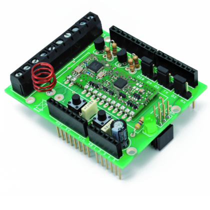
The Shield

The shield that we have created supports the 5V powering modules, both in serialized and non-serialized version, and has some jumpers to set up the communication interface so that the most wide usage possibility is given.
The communication with the RFTide modules occurs in serial mode, with TTL levels and at the speed of 19.200 bps, and can easily be managed by means of a serial port, that can be hardware or software by Arduino.
The JPRX and JPTX jumpers allow to select to which Arduino pins the AUART lines (internal to the RFTide module) will be connected. By positioning the JPRX jumper on RX, the TX module line will be addressed towards Arduino’s pin 0, that is to say the reception pin of Arduino’s hardware module to which, we remember, the USB-serial converter module of the board is connected. By positioning the JPTX jumper on TX, the RX module line will be addressed towards Arduino’s pin 1, that is to say, the transmission pin of Arduino’s hardware module, to which the USB-serial converter module of the Arduino’s board is connected, again.
To allow Arduino to freely communicate with the PC, be it for programs download or for the serial monitor operation, the shield takes into account the possibility to connect the two lines of the RFTide module (TX and RX), to two generic digital Arduino’s pins (D3 and D2), that can be used as serial software (virtual UART), thanks to the softserial library, integrated in Arduino’s IDE, and therefore leaving free space for the communication between Arduino and the PC.
The JPEN jumper allows to assign the Enable line of the module to Arduino’s digital line D9 or D10; this line, brought at a high logical level, allows to enable the module that otherwise would remain inactive with a reduced current consumption.
The shield power supply is directly taken from the +5V Arduino pin and, we remind it, its consumption is just 10mA when receiving, and 33mA when transmitting; in power down mode, the electricity absorbed doesn’t exceed 4µA.

Aurel modules need an external antenna that can be connected to the Y pin of the shield; the easiest way to create an antenna (and the one suggested by Aurel itself) is to weld a simple piece of rigid copper wire (1 mm wide, 85 mm long) directly on the platform. The length of 85 mm allows to have a tuned antenna at ¼ wave on the frequency of 868 MHz. The range is really remarkable and reaches some hundreds meters in beeline without obstacles, which is more than enough for a rich dwelling, even without needing to use repeaters.
From some tests we performed, we verified that even a simple whip antenna (made with a piece of copper wire that is bent on the shield) assures a more than optimal range, and at the same time allows to reduce the hindrances, so to be able to mount other shields over the one from RFTide.
It must be said, however, that this solution might reduce the range, because of the screening effect produced by the shields tracks applied above.
On the board two GPIN0 and GPIN1 inputs are available, and they operate under positive logic, therefore a possible contact will have to be connected between the input pin and the +5V power source. Seen the specific form of the Aurel modules’ inputs (see the previous article), they operate even by supplying continuous voltage between the GND and the input, for a value comprised between a few volts and 12 volts. The two GPOUT0 and GPOUT1 outputs are connected to the base of two transistors, used in open-collector mode, and they’re useful to activate small loads powered at +5V or at Vin, as in the example with the relays.
The board also implements Arduino’s Reset button, that would be difficultly accessed with the shield connected.
With the configuration we adviced, the shield turns out to be compatible with both the Motor Shield and the LCD Shield, that are both distributed in our store; the compatibility is granted by setting the jumpers of the various shields in accordance to Table 1 and Table 2. Even the SPI and I²C ports are not engaged by this shield.
Table 1 – Use with LCD Shield :
| Shield | Used Pins |
| RFTide | D2, D3, D10 |
| LCD | AN3, D4, D5, D6, D7, D8, D9 |
Table 2 – Use with Motor Shield:
| Shield | Used Pins |
| RFTide | D2, D3, D10 |
| Motor | D4, D5, D8, D9 |
RFTide modules do not allow a radio communication in transparent-mode, thus it is not possible to use them to substitute a serial wired communication with a wireless one (as it could instead occur with Xbee modules); broadcast is in fact carried out, as we will see, only for packets having a fixed length of 8 bytes.
Aurel modules can be programmed by means of serial commands, implying that convenient strings are sent (along with some parameters) in accordance to a proprietary standard, that is not compatible with the AT standard used by bluetooth and GPRS modules.
For an easy and immediate management, we therefore decided to write down a convenient library that would free the user from the need to know the modules in detail, if not for specific purposes. The library communicates with the Aurel modules by means of the software serial, thus the jumpers will be set up in the D2, D3 mode, and the Enable line on D10. Anyway, the library allows to define the pins you’re using to your liking, so to manage the modules in a way giving the greatest freedom as for the management of the hardware pins (provided that they’re not the ones used by hardware serial); this is done so to help even those who will test the modules simply by using an experimental breadboard and some jumpers.

Let’s see now in detail how to use the library whose sources are available, along with the files of this article, on the magazine’s website, but they may also be downloaded from the repository at the address: https://github.com/mircose/RFTide-shield-Arduino. The availability of a repository allows an easier distribution of later versions of the library that, being in a development phase, could undergo some modifications.
Once the files are downloaded, it is enough to unpack them within Arduino’s LIBRARIES folder; for any clarification please make reference to the website http://arduino.cc/en/Guide/Libraries.
At the end of the operations you will find a folder named RFTide installed, and it will contain the files function.txt, keywords.txt, readme.txt, RFTide.h and RFTide.cpp and a folder named Examples.
The readme file contains some pieces of information concerning the version of the library, while the function file contains a list of all the implemented functions, and the RFTide files represent the out-and-out library.
During the first boot of Arduino’s IDE, a new library will be loaded and the examples found in the Examples folder will be made available.
Connect now the shield to Arduino and set up the jumpers correctly, connect then everything to a PC by means of the dedicated cable. If the RFTide module has just been bought, it will have the default settings chosen by the manufacturer; if you do not know his settings, it would be better to reset it and bring it back to the factory state (default parameters) via the dedicated procedure:
1) press (for about 2 seconds) the LEARN button that is there on the shield until the LD1 LED is lit and shining with steady light;
2) within 15 seconds, press again (still for about 2 seconds) the LEARN button until the LD1 LED starts to flash.
Once the reset procedure is complete, the LD1 LED turns off.
At this stage it is advisable to verify that the module operates correctly; for the purpose, let’s interrogate the local module by using the example named LocalStatus.ino. Load the example and open Arduino Serial Monitor, by setting a communication at 9.600 bps; in the Serial Monitor window the module configuration will be shown.

In the case of the example, in which a non-serialized module is used, the address and the NetworkID will be zero, the firmware will be version 3.2 and no specific profile is programmed.
At this stage we may go to directly manage the outputs state and read the inputs state by loading the LocalIO example. It is advisable to connect at least a LED and a button to the shield.

The sketch sees to alternately activate the GPOUT0 output and to bring the state of the two GPIN0 and GPIN1 to a point that can be seen in figure.

At this stage it is interesting to use a second module to create a small wireless network. Let’s make a second module operational, by using for example a stand-alone circuit as the one we already presented. As in the previous case, it is advisable to interface a LED and a button.

The powering may occur via a simple non-stabilized power source, set up at 9V. Make sure that the module shows the factory settings; if it wasn’t so, do apply the reset procedure as previously described.
At this stage, it is needed to associate the new module to the network, and to do so we shall use the example named Network.
Boot SerialMonitor by setting a communication at 9.600 baud, and press the LEARN button on the remote module until the LED flashes. Send then the address to assign to the module, within 15 seconds and by means of the SEND command of SerialMonitor: for example 2; the LED will flash for a few seconds and then turn off. The address must be different from the one of the local module, detected for example by LocalStatus. Via the SEND command, type in the “p” letter to visualize the list of modules connected to the network. The local module is not detected since the modules cannot communicate with themselves.

At this stage you will have created a network with two modules, and it is possible to interact with the remote one, as we did at a local level.
Open and load the RemoteIO example, that will provide to activate alternately the GPOUT0 output on the remote module, in addition to reading the inputs state.
The module’s address with which to interact is reported at the line byte remoteAddress = 2 that, obviously, will have to be modified by reporting the address of the remote module assigned with the LEARN procedure previously described.

With the same association procedure, you may add to the network all the modules you wish, provided that each one has an univocal address; afterwards it is enough to specify the module address with which you want to interact.
A peculiarity of the library is that it allows different modes to access the GPIO pins state. In the LocalIO example, the reading of the inputs state may occur in three different ways, the first of them being:
IOSTATUS InOutStatus = rftide.localIoRead();
Serial.print(InOutStatus.getGPIN0);
In this case, the localIoRead function is used to read the state of all the GPIOs, while the INOUTStatus.getGPIN0 function shows the value of the GPIN0 pin, extrapolated from the previous reading.
The second mode goes as follows:
Serial.println(rftide.localIoRead().getGPIN0);
In this second case we use the previously seen localIoRead function, but with the mode to access the value of the getGPIN0 variable.
The third one envisages the instruction:
Serial.println(rftide.getGPIN0());
In this much more intuitive and immediate third example, the getGPIN0() function is used: it directly shows the state of the GPIN0 pin.
Let’s see now how to use the advanced functions to send and receive simple data strings by means of the PAN network.
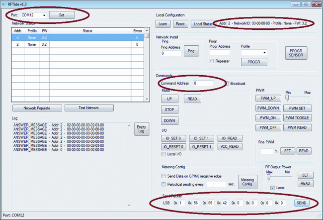
Use a RFTide stand-alone module and connect yourselves with the dedicated connector to the USB-Serial FT782M adaptor, in turn connected to a PC via a convenient cable. The board powering occurs by means of the FT782M module.Verify which virtual COM port is created at the moment of the connection of the USB-Serial converter; then boot the official software distributed by Aurel and named RFTide-v1.0 and specify the communication COM port consequently (SET button).
By means of the Local Status command, verify that the module is correctly recognized.
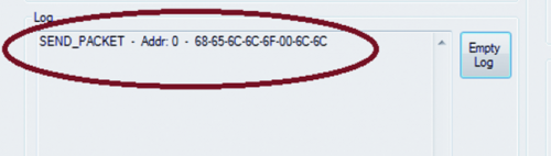
From Arduino’s environment open the ReadPacket example and load it on Arduino’s Board, with a RFTide shield connected, then open Serial Monitor and set up a communication speed of 9.600 baud. Use Aurel’s software to send a data packet to the shield: type in the shield address (for example, 0) in the Command Address field, type in the bytes to send in the Send Packet fields, then click on the SEND button.
On Serial Monitor, the received data will be visualized and the network address from which they’ve been sent will be indicated.

Open now the SendPacket sketch and specify the address of the remote module to which you want to send your data, on the line byte remoteAddress = 2; open then Serial Monitor and set “A capo (NL)” as sending mode, then type in the string to send (8 characters maximum) and click on SEND.
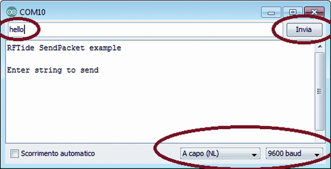
The string will be sent to the remote module that will repeat it on the serial port and will be visualized by means of Aurel’s software.

Let’s see the structure of the library in detail and how it can be used at its best. It is important to copy the first lines in the sketch, as they are the ones including the library in the project:
#include <RFTide.h>
#include <SoftwareSerial.h>
The syntax allowing to create the RFTide object is as follows: RFTide rftide(RX, TX, EN)
in which RFTide is the name associated with the object, while the RX, TX and EN values specify the pins that have been used for the communication between Arduino and the module; all the digital pins can be specified, with the exception of 0 and 1 that have already been occupied by the hardware serial. For example, the function activating an output on the remote module is called remoteIoSet, and the correct syntax considers that the module’s remote address we want to access and the remote pin we want to activate are specified as parameters:
rftide.remoteIoSet(remoteAddress, GPOUT0)
Notice that the GPOUT0 term can be used in place of the numerical constant 0 (zero), since within the library the keywords have been specified:
//define RFTide pin
#define GPIN0 0
#define GPIN1 1
#define GPOUT0 0
#define GPOUT1 1
Once this function has been recalled, the library will provide to create an 11 bytes packet that will be sent to the remote module:
outPacket[CommandLSB]=CMD_RIOSET;
outPacket[CommandMSB]=0x00;
outPacket[Address]=nodeAddress;
outPacket[Byte0]=payload;
The packet thus composed will be sent to the remote module, and the function allowing to analyze the return packet is immediately activated; the packet is always sent from the remote module as a confirmation of data reception. The analysis of the return packet allows to understand how the transmission went: if the packet arrives within the established time period and it contains the identification bytes of a reply packet, the transmission came to a successful conclusion; otherwise the STATUS variable contains the error code in trasmission, indicating if the packet is lost, incomplete or corrupted.
//define status value
#define ANSWER 0 //receive correctly answer
#define NOANSWER 1 //no answer received
#define BADANSWER 2 //bad data on receive buffer
#define BRKANSWER 3 //incomplete data on receive buffer
#define RECPACKET 4 //receive packet
If a data packet is received, the STATUS variable will show the RECPACKET value. The STATUS variable may always be interrogated after each transmission, in order to verify its effectiveness, by means of the rftide.status() function. Those who are experienced in libraries for Arduino will have no trouble in expanding the implemented functions, since the code is thoroughly commented and already divided in functions that can be easily recalled.
List of the functions implemented in the library version 1.0.
RFTide(byte RX_pin, byte TX_pin, byte EN_pin) Constructor
void localIoSet(byte payload) Set Output in local module
payload=0 set GPOUT0
payload=1 set GPOUT1
void localIoReset(byte payload) Reset Output in local module
payload=0 reset GPOUT0
payload=1 reset GPOUT1
IOSTATUS localIoRead() Return IO status in local module
byte getGPIN0 (0=OFF, 1=ON)
byte getGPIN1 (0=OFF, 1=ON)
byte getGPOUT0 (0=OFF, 1=ON)
byte getGPOUT1 (0=OFF, 1=ON)
int getADC0
int getADC1
NTSTATUS localStatus() Return status in local module
byte getAddress
unsigned long getNetworkID
int getFWversion
byte getProfile
byte getLocalAddress() Return address of the local module
int getLocalFWversion() Return firmware versione of the local module (format XYY)
byte getLocalProfile() Return profile type of the local module (0=none 1=motor 2=PWM 3=metering)
void resetLocalDevice() Reset local module
unsigned long getLocalNetworkID() Return NetworkID of the local module
void remoteIoSet(byte nodeAddress, byte payload) Set IO in remote module
payload=0 set GPOUT0
payload=1 set GPOUT1
void remoteIoReset(byte nodeAddress, byte payload) Reset IO in remote module
payload=0 reset GPOUT0
payload=1 reset GPOUT1
IOSTATUS remoteIoRead(byte nodeAddress) Return IO status in remote module
byte getGPIN0 (0=OFF, 1=ON)
byte getGPIN1 (0=OFF, 1=ON)
byte getGPOUT0 (0=OFF, 1=ON)
byte getGPOUT1 (0=OFF, 1=ON)
int getADC0
int getADC1
void progMessage(byte nodeAddress, byte nodeProfile) Program remote module for associate to network
nodeProfile: none, motor, PWM, metering,repeater
NTSTATUS ping(byte nodeAddress) Ping remote module and return remote status
byte getAddress
unsigned long getNetworkID
int getFWversion
byte getProfile
byte getGPIN0() Read value of GPIN0
byte getGPIN1() Read value of GPIN1
byte getGPOUT0() Read value of GPOUT0
byte getGPOUT1() Read value of GPOUT1
int version() Return a version of library
format is XYY (100 is V1.00)
void enable() Enable module
void disable() Disable module
void sendPacket(byte nodeAddress, char payload[]) Send packet to remote module
nodeAddress = address mof remote module
payload = 8 byte of data
byte readPacket(byte inbyte[]) Read fixed 8byte Packet received from remote module
If valid data is available return address of remote module else return 255.
Data received is saved in the inbyte array
byte status() Return status of the last operation
ANSWER receive correctly answer
NOANSWER no answer received
BADANSWER bad data on receive buffer
BRKANSWER incomplete data on receive buffer
RECPACKET receive packet from remote
From Store
