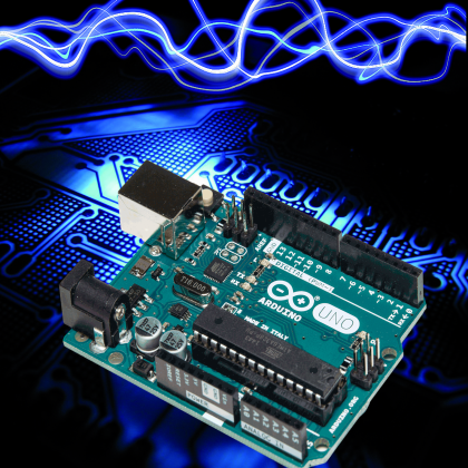
Let’s deal with the problems of the various powering modes for the most famous Arduino boards, in order to overcome doubts users may have and to provide useful advices.
When you want to use an Arduino board in stand-alone mode, the first problem to face is the one of how to power it, once it is disconnected from the computer’s USB port. Unfortunately, a faulty knowledge of the theme of powering sometimes leads people to make unforgivable mistakes, since the first result is often that of seeing the board go up in smoke and almost always irremediably, since from that moment it will not work any more.
In the premise it is good to point out that the article will deal with the powering modes of the Arduino boards operating at 5 V (UNO, MEGA, Duemilanove); a short, specific note will be dedicated to Arduino YÚN, that is still a 5 V board, but with features that are different from the other ones.
THE EXTERNAL POWER SOURCES
Basically, in addition to the computer’s USB port, the external power sources for Arduino are: linear and switching power supplies, or having a specific USB output (that most likely is of the switching kind) and batteries of various types.
THE POWER SUPPLIES
Amongst the many mistakes that are made, there is surely the one of recycling power supplies kept in a drawer, and by treating them as if they were all the same. Let’s start immediately by making it clear that those of the alternating current kind have to be absolutely excluded (they were used a lot by the analog modems of some years ago). In the figure we can see the comparison between the two power supplies that are very similar, from a physical point of view: one operates on alternating current (AC) and the other one on direct current (DC).
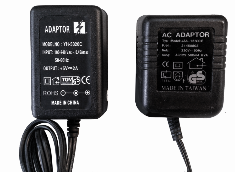
Comparison between power supplies operating on AC and DC
As it can be noticed from the symbols found on the respective tags, it is quite simple to distinguish the two models, even though they are physically similar.
In the alternating current model, shown on the right side of the figure, the line with the indications concerning the output says: AC 12 V 500mA 6VA, that respectively represent: alternating current, maximum output load and power, expressed in VA (that can always be obtained by means of the P = V*I formula). In some cases, in the place of the AC abbreviation, the symbol “~” may be found, and it still means “alternating current”.
On the left, on the contrary, the direct current model, in the line with the output values shows in an equally clear way +5 V 2A, moreover the symbol “═” graphically points to the direct current; finally, in these power supplies, the voltage polarity is always indicated on the output JACK; in this case the graphics represented on the tag indicates that the positive pole (+) is connected to the central part of the jack while the negative pole (-) is connected to the external part. We may still notice the presence of the “~” symbol on the tag, but it is clearly referred to the power supply input that, obviously, must be connected to the alternating current network.
In the course of this article we will talk about direct current only, having already clearly ruled out the alternating one for our purposes. Basically, the power supplies can be divided in three categories:
Unregulated linear power supplies: an unregulated linear power supply always takes into account an AC transformer converting from 230 Vac to a definitely lower value (usually from 3 to 24 Vac), a diode bridge rectifier (that has the task of converting the alternating current into direct current) and an electrolytic capacitor for filter and levelling. There are the so-called “multiple winding” models that have a transformer with a single primary winding for 230 Vac and many different secondary windings, and it is capable of supplying different alternating current voltages that, by means of a commutator, are connected (only one per time) to the diode bridge and to the capacitor, and therefore to the output. By measuring the behaviour of an unregulated power supply (regardless of the fact it is a single or multiple winding model) with a normal multimeter, it is possible to immediately notice how the voltage, in the absence of load, may be definitely higher than the nominal one, while in the presence of a load it proportionally decreases, depending on the current draw of the last one, decreasing even under the level of the nominal voltage. These power supplies do not offer any reliability and are often even harmful for the machineries that, if absorbing little, are powered at voltages that are much higher than the required ones. Consequently, they are absolutely to be avoided!
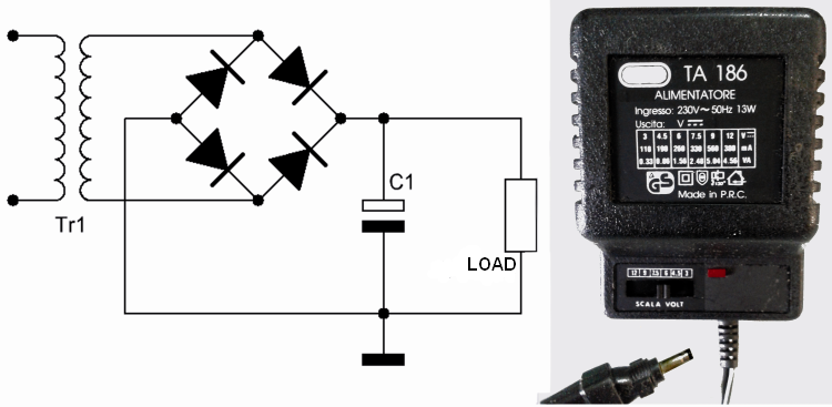
Unregulated linear power supply
Regulated linear power supplies: this kind of power supply is characterized by the presence of further electronic components, in comparison with unregulated models, such as a voltage regulator and other capacitors with filter and anti-self-oscillating functions. In the greatest majority of cases they are single voltage tools, and very reliable ones, of dimensions that are proportional to the deliverable power; the voltage is very stable (typical variations of ±0,1V in respect to the nominal value), regardless of the current (always within the limits of the nominal value). In addition to an excellent stability, they have a very low ripple value (the residual variation of alternating current over direct current), but their performance is quite low (between 40% and 60%) since much power is dissipated by the regulator that, for this reason, may require a dissipation system that can even be quite bulky. The power dissipation is directly proportional both to the drop-out (the difference between input voltage at the regulator and output voltage from the same) and to the deliverable power. Moreover, the greater is the dissipated power, the greater is the temperature reached by the regulator’s case and, consequently, the lesser is the deliverable power. For such reasons the input voltage should always have a slightly higher value than the nominal one of the regulator. These power supplies are ideal for applications whose noise (ripple or high frequency) may prove harmful to the proper functioning of the circuit, typically when dealing with very low voltages. In general, they require an input voltage corresponding to the one of the electric network (230 Vac) or with quite a narrow range (220-240 Vac), moreover they are quite bulky.
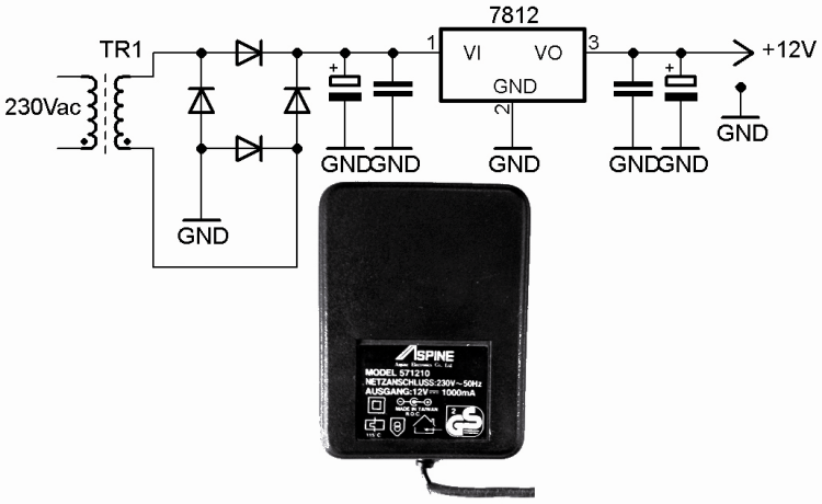
Regulated linear power supply
Switching power supplies: this last family of power supplies is the most recent, from a technological point of view; it is based on a high frequency work system and it is capable of regulating the output voltage at a value that is lower (step-down) than the input one (as in the case of the kind seen before), or at a higher value (step-up). The design of these systems is much more complex than the linear ones, but recently many integrated circuits have been put on the market, and with the help of a few external components, whose values can be calculated with the help of the data-sheet, and that make their creation quite easy. The dimensions are very limited, because of the high efficiency of such technology (80-90%) and even the stabilization is excellent. On the other hand, in respect to the regulated linear models, these power supplies have high ripple levels in addition to high frequency noise, which makes them not suitable to power circuits that suffer from such residual presences on powering. In general, they operate with a wide range of input voltages (100-240 Vac) and have dimensions that are definitely much smaller than their counterpart of the linear kind.
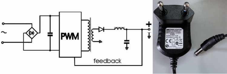
Switching power supply
A particular type of switching power supplies is the one of mobile phone chargers; in general their usage is inadvisable since they have been designed for the exclusive purpose of recharging the battery, and thus often paying little attention to the noise filtering. Some models even incorporate the control system of the battery charge power, for example the ones for LiPo or Li-Ion batteries, thus making them totally unsuitable to power circuits that are different from the ones of a mobile phone.
THE BATTERIES
It is important to deal briefly with the problems connected with battery powering, since the need to make a circuit independent from the home electric network is not rarely felt. When deciding to resort to battery powering, the ratios between their capacity (usually expressed in mAh) and the power required by the Arduino board and the peripheral circuitry connected to it are often neglected, thus leading to results that are often disappointing (autonomy is very low or the system does not turn on at all).
In figure we represented an overview of the most commonly used battery types.

Batteries Overview
Since a single battery cannot always satisfy all circuital needs, because of the low voltage value and/or low capacity, it becomes important to understand the series and parallel mechanism, that is to say, the ways with which two batteries may be connected between them to increase the said values. As a premise it must be very clear that all the batteries that will create a “pack” must be absolutely identical and possibly coming from the same batch; in the case of alkaline batteries they must strictly be new, in the case of rechargeable batteries all of them must be either fully charged or discharged.
Identical batteries, connected in parallel (all the positive poles between them and all the negative poles between them, see in figure) keep the same nominal voltage of a single one and sum up the capacities: e. g. four 1,5 V 200 mAh alkaline batteries connected in parallel make up a 1,5 V battery with a capacity that is equal to the one of a single battery multiplied by four (800 mAh). One resorts to this system when the voltage of the single battery is enough to power the circuit but a greater autonomy is needed.
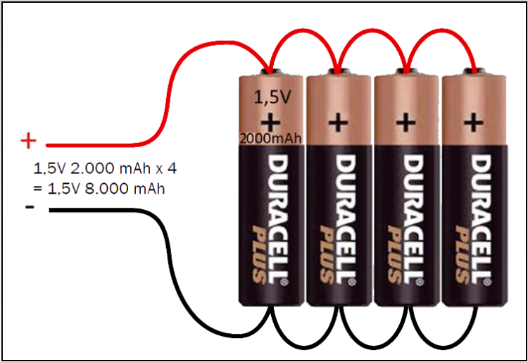
Battery Pack in parallel
Identical batteries, connected in series between them (the negative pole of the first one goes to the positive pole of the second one, and so on), keep the capacity of the single battery and sum up the voltages: e. g. five 1,2 V 2000 mAh NiMh batteries, connected in series, make up a 6 V 2000 mAh pack. The connection in series is used when the single battery has a voltage that is too low and is unable to power the circuit; in fact in the specific example, with a single 1,2 V battery we could never power Arduino, and not even with 2, 3, or 4 batteries in series, since we would obtain 2,4 – 3,6 – 4,8 V respectively, and these wouldn’t still be enough for the purpose; on the other hand the fifth battery enables us to reach a 6 V tension that can be applied, for example, to the Vin pin, as we will see.
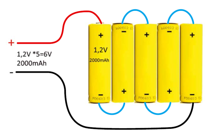
Battery Pack in series
Of course, it is possible to combine the two types of packs, when in need to increase both the voltage and the current. For example, by connecting in parallel two packs already connected “in series” and made up by five 6 V 2000 mAh NiMh batteries (the pack described just a while ago), it is possible to obtain a 6 V 4000 mAh pack.
Hermetic Lead-Acid batteries are packs made up by 2 V elements that are connected in series; usually they are used alone, since they exist in various “sizes” as for voltage and capacity, but they still can be used in series or in parallel.
It is quite a complex thing to create Li-Ion or LiPo battery packs (the single cells must be “balanced”) therefore it is definitely more convenient to resort to commercial products. There are, however, specific battery chargers for these models’ packs, since each cell of the pack must be charged individually.

Battery charger for LiPo/Li-Ion batteries
It is necessary to keep into account that the recharge system used by LiPo/Li-Ion batteries is very different from the one used by NiMh or hermetic Lead-acid batteries, thus you have to read up correctly before adopting any kind of batteries for your own project.
As regards autonomy, the calculation is quite a simple one, even though the thing gets complicated in the cases of “multi voltage”; in general it is enough to operate a division between the global capacity of the battery (expressed in mAh) and the circuit power consumption (expressed in mA) so to obtain the autonomy time (expressed in hours).
For example, an hermetic 12 V 2400 mAh Lead-acid battery, powering a circuit requiring 12 V 300 mA overall, guarantees a maximum autonomy of 2400/300=8 h(ours).
LiPo/Li-Ion batteries have the peculiarity to be able to deliver, even if for a very short time, current for values that are definitely greater than their nominal value, therefore they are very used in fields that require high inrush currents. On the other hand, they do not lend themselves for the creation of the so called “buffer” applications, that is to say, when a circuit is normally powered by the electric network and the batteries, constantly kept under charge, are used only when the power goes out (for example, in domotic installations), since they would get damaged in a very short time.
In these cases, the most suitable batteries are Lead-Acid ones, while NiMh or, worse, the older NiCd, suffer from the so called memory effect, thus it is better to use them until they are fully discharged to recharge them again.
For the usage as buffer, the Lead-acid batteries are definitely advisable, since they can be left constantly under charge, thus lending themselves to the task.
There are however recharge control circuits, very sophisticated ones, that in some cases allow some exceptions to what has been stated above.
THE INPUTS FOR POWERING
Now that we have quite a clear idea of the possible external power sources, we may see how to apply them to Arduino. Everything we will describe in this paragraph can be applied to all the kind of sources previously described, thus both power supplies and batteries. We point out again the need to pay maximum attention to the polarities: it is very important to connect properly the positive and the negative poles to the Arduino board, otherwise there is the risk to see nothing work or even to make irreparable damages. In fact, while in some cases there are some intrinsic protections on the board, in other cases the polarity inversion might cause immediate damages!
Arduino has four possible powering inputs:
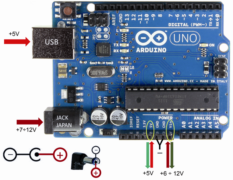
Arduino’s powering inputs
1 – USB Port: 5 V have to reach this socket (different voltages are not allowed, absolutely!), coming from a computer’s USB port, or from any power supply that is provided with a USB port (in general, they are small size power supplies, suitable to power devices that are provided with a USB cable). If the powering comes from a computer, there is a current limitation of 250 mA or 500 mA, depending on the USB port of the said computer; if on the other hand you are using an external power supply, the maximum output current (regardless of the one guaranteed by the same power supply, that in general is a maximum of 1 A or 2 A) is anyway limited to 500 mA by the PTC self-resettable protection fuse.
2 – JAPAN JACK socket: an external source (a power supply, usually) must be connected to this socket, with the positive pole going to the central part of the jack, and the value must be ranging between 6 V and 20 V, even though the range recommended by the manufacturer is 7÷12 V, thus it is not advisable to use voltages that are lower than 7 V or greater than 12 V, if not in the case of a real need; 6 V may not guarantee a proper stabilization on the part of the regulator, it is in fact needed to consider the voltage fall of the protection diode, placed in series at the regulator’s input (whose purpose is to preserve the board from destruction in the case of polarity inversion on the jack); while values above 12 V would create an excessively high drop-out (an electric potential difference between the regulator’s input and output) that would cause a pointless overheating of the regulator, even with low levels of current draw.
3 – Vin socket: this socket has a dual function.
3a – input for external powering, not protected by polarity inversions: in fact the connection goes directly to the regulator’s input and below the JACK socket’s diode; of course no voltage must be applied to the jack socket, otherwise dangerous conflicts might arise;
3b: output from which to draw the voltage applied to the JACK socket, detracting the protection diode’s fall. It might prove useful to power small loads, requiring a voltage higher than 5 V and equal to the one applied to the JACK socket (always considering the diode’s voltage fall).
In both cases the voltage negative pole can be found on the board’s GND sockets.
4 – 5 V socket: it is directly connected to the regulator’s output, thus the 5 V to power external loads to Arduino can be drawn from it. In the case voltages are not applied to the USB Port or to the JACK socket, the 5 V socket can be even used to power Arduino directly, if having an external stabilized 5 V source. One has to consider that, in general, regulators do not like voltages being applied to their output, but in this particular case this situation turns out to happen even when powering Arduino from the USB port, therefore we may assume that the designers judged this problem as harmless. Even in this case there is no form of protection, since both the diode and the PTC fuse are found above this socket and thus they do not have any active function. As in the case of the Vin socket, the voltage negative pole can be found on the board’s GND sockets.
NOTE: regardless of the input used, Arduino has a 3.3 V output socket to power loads operating at this voltage; in fact a second regulator, right for the purpose of generating 3.3 V, is directly connected to the 5 V. This socket cannot be used as input.
CONFLICTS MANAGEMENT
Arduino is provided with a comparison circuit that controls a type P MOSFET; if a tension is found on Vin (powering from the JACK or from the Vin socket), the MOSFET is interdicted and the possible presence of voltage coming from the USB port is ignored; in the opposite case, the MOSFET will connect the USB port’s 5 V to the 5 V socket, hence below the regulator, thus powering Arduino.
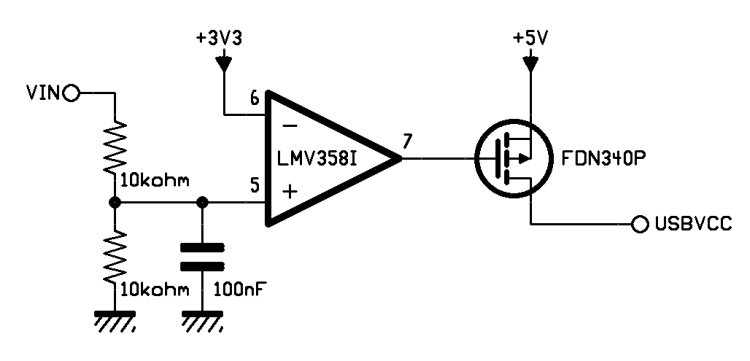
Management circuit of the power conflicts
Therefore it is clear that if you apply the voltage to the USB port and an external source to the JACK socket at the same time, it will be this last one to power the circuit, while the USB connection will keep working for the data exchange with the computer and no longer as a power source. We remind that in both cases the 5 V socket cannot be used as input, but only as output.
THE CHOICE OF THE INPUT
Having now a clearer picture on the subject of the power sources and the various inputs offered by Arduino, it is necessary to decide which of the latter should be used for each specific project. The choice must obviously be made on the basis of the source available, but also on the basis of the external peripherals to be powered.
It must be noticed that, as regards the current delivered, it is important that the source is capable of making it available for as much as needed by the maximum load, to be increased by about 20%, in order to avoid that the said source works at the limits; it then has no importance if the increase is by 50% or even 100% greater; in fact if the power supply is capable of delivering 2 A and the load required is only 100 mA (thus 20 times less), there is no risk to damage things, since the residual power quantity will simply remain “available”.
On the other hand, it is extremely dangerous not to take the voltage into account, since it has never to exceed the limits provided or allowed; for example for no reason it will be possible to apply voltages exceeding the 5 V socket even by a single Volt, since the board’s integrated circuits would burn immediately!
1 – USB Port: this one is handy for experimenting with small loads, requiring 5 V, since it enables the dual function of powering and programming the board; the power limit imposed by the PTC fuse is 500 mA, and actually, these components tolerate up to almost twice the value before a protective intervention, but it is better to consider the nominal value; the polarity on the USB socket is a standard one and thus does not cause problems;
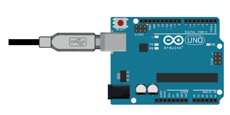
Powering Arduino by means of USB Port
2 – JAPAN JACK Port: in general, one resorts to this port to increase the power availability on the 5 V (within the limits allowed by the regulator) and/or to have available a voltage greater than 5 V, in order to power external loads. For example, if you have to power a 12 V relay, Arduino’s pin alone is not enough, but it can be used to pilot a transistor that will bring, as a conductor, the 12 V needed by the relay. In this case a 12-12,5 V voltage is applied to the JACK socket, Arduino’s board is powered by the regulator’s 5 V and from the Vin socket it is possible to draw 12 V to send to the relay (by means of an appropriate circuital configuration); the positive pole must be applied to the JACK’s central pin, the negative pole to the external one;
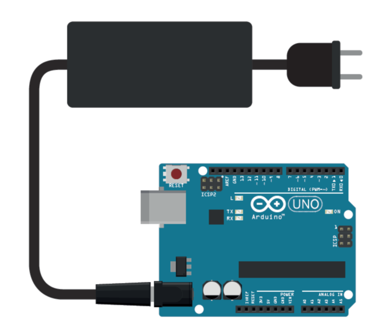
Powering Arduino by means of a JAPAN JACK socket
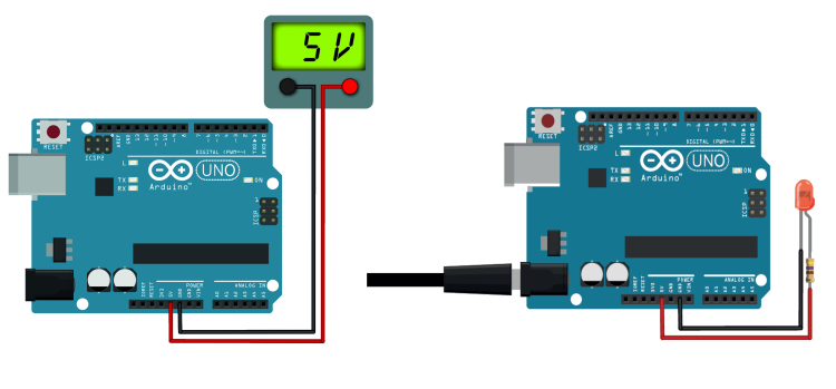
3 – Vin socket: as said before, this one can be useful as input if an external voltage is needed and you only have 6 V available, in fact the Vin socket bypasses the protection diode and the regulator may operate properly; or it may be useful to draw the voltage coming from the JACK socket; considering the fact that the Vin socket is unprotected, its usage by the unexperienced is definitely not advised. The positive pole must be connected to the Vin socket, the negative one to the GND. In figure you can see Arduino powered via the Vin socket on the left, while on the right it is powered by means of the JAPAN JACK socket and from the Vin the voltage to light a LED is drawn.
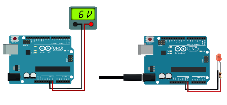
The Vin socket used as input or as output
4 – 5 V socket: even in this case it should be preferable to resort to drawing rather than to inputing voltage, given the enormous risks that are taken when missing protections; one of the possible situations in which this socket comes in handy is the one of having a stabilized 5 V power source but without a USB jack; as previously seen it is necessary to apply at least 7 V to the JAPAN JACK socket and at least 6 V to the Vin socket, thus this socket is the only one capable of accepting 5 V exactly. Going back to the relay example, if having the availability of a model operating at 5 V, but that requires a greater power than the one delivered by one of Arduino’s pins (that cannot exceed 30-35 mA), even here the problem would be solved very well with a transistor and by drawing 5 V from this socket. The positive pole must be connected to the 5 V socket, the negative to the GND.
The 5 V socket used as input or as output
THE LIMITS OF THE CURRENT
Let’s start by remembering that you cannot pretend to power a load requiring a certain current, without the source being capable of delivering it, and that any load draws the power it needs and not the available one. Let’s see some examples, assuming that Arduino will draw the maximum possible (200 mA), the rest is then absorbed by the external components:
a – Global current consumption of 400 mA; in this case it is possible to power everything via USB, on the condition that the computer’s port (or the power supply with USB output, used as its substitute) is capable of delivering all the 500 mA considered as maximum limit;
b – Global current consumption of 600 mA; in this case it is NOT possible to power the circuit via USB since we saw that the limit set by the PTC protection fuse is of about 500 mA; we have then to resort to an external source applied to the JACK port, one that is capable of guaranteeing a current that is greater than the one required by at least 20-30%, thus for a total of at least 600-700 mA, and as stated before the exceeding current available is not used. The voltage for the peripherals can be drawn from the 5 V pin. As already seen, however, the USB connection may be kept for the programming of the micro or for the usage of the serial monitor.
c – Let’s see the case in which the total drawing is 1A; even in this case we have to resort to an external voltage to be applied to the JACK, but as we will see in the next paragraph we are operating at the extreme limit of the regulator, thus it will be needed to separate Arduino’s powering from the one of the external loads.
In the case in which there are no peripherals requiring a voltage greater than 5 V, for example 12 V, it is needed to resort to an external power supply, applied to the JACK socket, but to understand how to draw the two voltages one must always assess the currents drawn by Arduino and the 5 V and 12 V loads. Let’s see some examples:
d – Let’s see the case of Arduino (200 mA), with 5 V (50 mA) peripherals and 12 V (300 mA) peripherals; by applying a 12 V power supply with at least 1 A maximum current, the limits of the regulator (that we will see in the next paragraph) enable us to power Arduino and its 5 V and the 5 V peripherals; as regards the 12 V peripherals, on the other hand we could draw that voltage from the Vin pin;
e – Let’s see the case of Arduino (200 mA), with 5 V (300 mA) peripherals and 12 V(1A) peripherals; by applying a 12 V power supply with at least 2 A maximum current, the limits of the regulator (that we will see in the next paragraph) will impose to power Arduino alone with its 5 V, while it will not be possible to use the Vin pin (see following NOTE), at this point it a different solution should be found.
NOTE: let’s consider another factor, this time concerning the Vin pin; apparently there should not be limits of deliverable current, in addition to the one imposed by the applied power supply; however all the current will have to flow within the protection diode, that is anyway quite sturdy, but de facto one has to consider that the copper track, that connects the regulator’s input to the Vin pin placed on Arduino’s POWER header, is not very thick and consequently may not endure high currents, as it would risk burning.
THE REGULATOR’S LIMITS
We now have to face the problem of the power the regulator has to dissipate; by reading the specifications on the data-sheet of the NCP1117ST50T3G regulator in the SOT-223 case (the one used on Arduino UNO r3) it can be seen that the maximum operating temperature is 150°C (being a “maximum rating” value one should keep himself at about 20% under it, thus let’s consider 120°C); it can also be read that the regulator reaches a temperature of 67°C for each Watt to dissipate, thus we can reasonably consider a maximum power to be dissipated of about 2W (actually the formula on the data-sheet calculates 1,87W at 25°C). We have already seen how to calculate the power by means of formulae; by opportunely moving the terms we can calculate the maximum deliverable power: for example I = W / (Vin-Vout). Let’s see some examples:
– 12 V Power Supply: I = 2 / (12-5) = 2 / 7 = 285mA
– 9V Power Supply: I = 2 / (9-5) = 2/4 = 500mA
– 7 V Power Supply: I = 2 / (7-5) = 2/2 = 1A
These calculations do not take into account the fall on the input diode, but are however based on a power that is greater than the advised one, thus we may consider them to be reasonable. It can be clearly inferred how it can be definitely preferable to apply the lowest power possible to the regulator.
In the previous “b” example, in which 600mA were needed, it can be well understood h now how voltages greater than 8V cannot be applied to the JACK, while in the “c” example we are definitely at the limits, even applying 7 V at the input, thus in this case we cannot think to make all the current flow through the regulator, but a different system has to be thought of; the same goes for the “e” example, while we have seen that the “d” example lends itself to the usage of a single internal power.
POWER SOURCES THAT ARE EXTERNAL TO ARDUINO
In the previously seen examples, we verified possibilities that go beyond the limits of the internal regulator and even of Arduino’s tracks; in these cases a possible solution is the one to create an external board that makes available a series of outputs to power both Arduino and the external peripherals operating at 5 V or other voltages (typically 9 V or 12 V).
– Let’s consider the “c” case: 5 V 1 A are needed, since 200 mA are allocated to Arduino and 800 mA to the 5 V peripherals; for example there can be a 9 V source with a deliverable power that has to be about 20-30% more, for example a 9 V 1,5 A or 2 A regulated power supply; it will be enough to create a small board with an input that is compatible with the power supply jack, below it uses a 5 V regulator (for example the classic 7805 with a TO-220 case and the typical four capacitors), whose exit will go to power the external 5 V peripherals; the 9 V from the external power supply will be brought as output as well and will be connected to a JACK pin for Arduino’s socket.
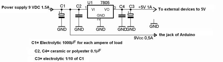
High power consumption 5 V circuit plan
– Let’s consider the “e” case: 5 V 500 mA are needed (200 mA are allocated to Arduino and 300 mA to the 5 V peripherals), and 12 V 1 A by the 12 V peripherals; for example there can be a 12 V source with deliverable power of at least 2 A; it is enough to create a small board with an input being compatible with the power supply jack, below a 5 V regulator is used (for example the previously seen 7805), whose exit will go to power the external 5 V peripherals; the external power supply’s 12 V will be brought as output as well and split on two sockets: one to be connected to a JACK pin for Arduino’s socket and the other one to be connected to the 12 V peripherals.

High consumption 5 V and 12 V circuit plan
NOTE UPON ARDUINO YÚN
In conclusion of this article, let’s leave a particular note concerning Arduino YÚN, given that, even if requiring 5 V, it has a powering system that differentiates it from all the other boards. Since it does not have a power regulator on board, it can be powered exclusively with regulated 5 V power sources:
- by means of its micro-USB port;
- by means of the Vin pin, to which we need to supply 5 V exactly, just because a power regulator below is missing.

How to power Arduino YÚN
Finally, we have to keep in mind that, on the contrary of other Arduino boards, YÚN cannot be powered by the 5 V pin on the lateral header. In fact, as it can clearly be seen on the original electric plan (pag. 5) on the 5 V pin, Arduino YÚN has a diode (D9) that allows the current to flow only as an output.
Sponsored Techno Tip: Arduino programmers can stay 24*7 productive by moving their programming and testing environment into the cloud with XenDesk with top-notch support from one of the best provider of cloud based solutions – Apps4Rent.
From the store
Starter kit with Arduino UNO – Basic Level

Good synopsis and the battery details especially are helpful.
One thing, is Japan Jack is more generally called a Barrel Jack (at least in the US, but also in parts catalogs).
Thanks for the article!
Hi nillocr,
sorry for late reply. Thank you for the clarification.
Best regards
hello nice guide, but i have a question
i have 6A 5v power supply (which i bought to power my 5v ws2812b led strip), so can i use this power supply to power the arduino considering its 6A!
will it be safe? the arduino will remain ON about 10 hours a day (not continuously though).
No problem.
Arduino eat what it needs
thank you.
My Website
Hello!
I am new to this educating forum. Can I power arduino Atmega2560 with a 5v 1A USB power bank: using the USB cable? Thanks in
Yes, you can power Arduino Mega with 5V 1A.
Cheers Mr. Michele Menniti!!!!!! I was initially concerned about the 500mA overcurrent protector.
Hi,
I clarify my answer. You may feed Arduino Mega using a USB 5V 1A generator, but the absorption of Arduino and accessory circuits must not exceed 500mA.
If you needs more than 500mA current, you must use the direct 5V input, on the “power” header connector, but at that point you can’t use the USB cable.
Cheers, Sir!!! I am not drawing more than 500mA. However, I am using the 12v <1A wall adapter. I hope the 7v drop is not too excessive for the regulator of the ATMEGA2560, Sir??
The answer is in this article: paragraph THE INPUTS FOR POWERING, point 2. ;-) 12V are the maximum limit.
Cheers, Sir!!!! Please accept my apology for this late reply.
The EEPROM memory has a specified life of 100,000 write/erase cycles, so you may need to be careful about how often you write to it.
Does the above sentence about arduino in general mean that each location of the EEPROM can only withstand 100k read/write??? Or does the above sentence only apply to all the locations in EEPROM ??? What forms a cycle in this case and when is a cycle completed?? Thanks in advance, Sir!!!
Hi,
I’m sorry but this blog concerns the Arduino power systems. I suggest you propose the question on the Arduino Official Forum.
If the issue still exists for you – pls take a look at: https://cybergibbons.com/uncategorized/arduino-misconceptions-5-youll-wear-out-the-flash-memory/
Could I power it with a 12V 30A computer power supply or will this blow the regulator?
Yes this is far more than adequate!!! It’s like using a sledge hammer to crack a nut. I’m using a computer power supply as a bench power supply. The 12V is the important bit, 30A is the max continuous current the power supply can supply. So basically as long as your Arduino and whatever else you have connected to the power supply doesn’t draw more than 30A (at 12V) in total, then your power supply should be able to cope.
Arduino should only draw 800mA (0.8A) at 5V before burning out. The 12V equivalent is calculated by converting to power at 5V, then back to current at 12V. P = IV = 5 x 0.8 = 4W. So the Arduino would take 4W at the max 5V current. So your power supply the other side of the 5V regulator would see I = P/V = 4/12 = 0.33 A with 100% efficiency in the voltage regulator. In reality you would probably find it draws a little more than that.
Basically you would be using 0.33A of the max 30A the power supply is capable of providing or 1.1% of the available current.
To correctly calculate the dissipation of the voltage regulator, You have to consider the drop-out between input and output of the voltage regulator. The formula is: P = Vin-Vout * I = 12-5 * 0.8 = 5.6 W. This dissipation is dangerous for the voltage regulator of Arduino.
Regards.
Thanks Michele! Always good to learn something new… I presume this only applies to liner regulators? You can get drop in replacement switching regulators now for about £1.20 vers £0.20 or less for a liner regulator.
Any idea how to work out the power dissipation for a switching regulator, or is it just a case of looking at the data sheet?
The switching regulators are not suitable for power microcontrollers, the switching frequencies disturb the clock.
The best solution is to provide a 6-7 volt input voltage or an external power supply of 5 volts.
The power dissipation can be read on datasheet of the component.
I use 5V Switching power for Pi and from there by usb is powered arduino.
Now if i use arduino 12v input then will it output 5v form usb to Raspberry?
And what happening when I connect PC to Raspberry USB port?
The Arduino USB port is unable to provide power output
[…] Feeding power to Arduino: the ultimate guide. Let’s deal with the problems of the various powering modes for the most famous Arduino boards, in order to overcome doubts users may have and to provide useful advices. When you want to use an Arduino board in stand-alone mode, the first problem to face is the one of how to power it, once it is disconnected from the computer’s USB port. Unfortunately, a faulty knowledge of the theme of powering sometimes leads people to make unforgivable mistakes, since the first result is often that of seeing the board go up in smoke and almost always irremediably, since from that moment it will not work any more. […]
Running a standard Arduino board with a battery will drain the cell very, very quickly. If want to run your project for long periods, have a look on this project: https://www.kickstarter.com/projects/340271897/wh…
It is designed to run on common AA batteries for longer periods and also counts with a wireless transceiver for long range communication! Cheers!
Running a standard Arduino board with a battery will drain the cell very, very quickly. If want to run your project for long periods, have a look on this project: https://www.kickstarter.com/projects/340271897/whisper-node
It is designed to run on common AA batteries for longer periods and also counts with a wireless transceiver for long range communication! Cheers!
Great article! I’m currently planning how to power a network of 3 Megas and tens of “nano 3”, interconnected via an RS485 multidrop bus. It will be the hearth of my brand-new, fully open & Arduino based, home automation system. It would be great to read a similar article focused on nano 3.
I have an Arduino Uno board with a GSM shield. The Uno gets its power from a 12vdc SLA battery, and the GSM gets its power from the Uno. This enables me to send SMS messages to the shield to be acted upon by the Arduino sketch – currently just turning on/off a 12vdc circuit via a relay. This setup worked fine in lab testing, but once we deployed it for field testing, the Uno board overheats and shuts off after a few hours. This seems to indicate an overload coming from the battery. Do I need to use a voltage regulator between the battery and the Uno? Thanks.
Yes, 7 volts dropout (12V – 5 Volt) are excessive for the Arduino UNO internal regulator. You need a step-down switch module to reduce 12V to 7V to obtain a dropout of only 2V.
Thank you. I will give that a try.
Hey,
I used arduino mega with gsm gsprs shield from itead studio.
The gsm shield need 2a to send data to database and if i used the 5v and 3a for the power.what do you think?
Can arduino handle this current?
No,
Arduino can’t manages more than 800 mA current, you must powering the shield directly, but you have to keep ground in common
This seems to be an interesting solution to run “Arduino” on batteries:
https://bitbucket.org/talk2/whisper-node-avr/overview
According to the documentation the whole board consumes less than 4uA when sleeping and can be powered by a single AA.
Hi, I have connected only the USB to my arduino mega, but the Vin pin show me 4.4V, looking the schematic of the mega Vin is separated from the USB port by the Mosfet and the Opamp…I cant fin why there are 4.4 volts in Vin pin.
HI, You’re right, according to the schematic, when feeding Arduino Mega via USB, the pin Vin should’nt show voltage; It may have broken the regulator IC1
Very nice article! But I have one question: I got a 12V / 2A power supply and I want to drive a stepper motor via the Arduino motor shield (L298P). Will the Uno-board feed the motor shield when I plug my power supply into the Uno-board? Or is the current to high for the pins?
Hi, the UNO board can’t deliver more than 800 mA; the motor shield should be powered directly.
Thanks for the great article lads.
I have a question about powering the Arduino with 12 v. My enclosure set up means the 12 v jack is right up against the side, and since I’m powering several devices I don’t want to drill a hole for the jack. I checked the voltage across the three jack pins on the underside of the board. The positive I located, but the other two pins are both reading -12 volts (my plan was to solder onto the jack pins under the board). Can anyone tell me the negative pin to use, or if this approach is even a good idea?
Thanks!
Brian
PS I have another question…
I am running a relay shield (the one that plugs into all pins on Arduino from above & with RFBee extension). It’s rated 7 – 12 volts, but recommends 9 v. I used a potential divider to drop to 8.3 v from the 12 v power supply. I know this is not efficient, but the losses aren’t a problem. Could the variable voltage cause an issue when the relays switch? The relays may be holding for up to 2 hours…
Cheers.
I am simply trying the blink program. it works perfectly while powered by the usb. But if I use a 12v adapter the orogram doesn’t execute. The arduino is powered on but the program doesn’t execute
I have been researching power soloutions and this is the most informative article I found but I still need to find a specific power solution to my project. I will be connecting 1 Uno (master), 2 LCD screens and 2 Megas all connected through the I2C bus. What I have read is all the devices on the I2C bus need to have their 5v and grounds connected together. I plan using one 9V 3A power supply to power the three Arduino and then connecting all the 5V outputs of the 3 Arduino together. Will this work or should I buy a 5v regulated power supply and power everything through the 5v pins and not use the Japan Jack.
My project is to control about 45 model railroad turnouts through relays controlled by the two Megas with the UNO managing kepad inputs, routing calculations and displaying routes on the LCD screens.
The relays and turnout motors are on their own 12v power supply.
Thanks in advance for any help.
For 9V 3A in the jack japan solution: the parallel connection of the three 5V outputs is not recommended. You must connect the masses but you must leave separated the positive poles.
The unique power solution with 5V for the entire circuit is preferred because there is less heat loss, in this case you can interconnect all the inputs at 5V.
Hello Michele and Friends,
The technical guide provided here is compellingly lucid, concise and highly appreciated. I work as a lab technician and interested in the Arduino unit.
In particular I am wondering about the power limitation of the linear 5V regulator, NCP1117ST50T3G. Given the power dissipation as: PD = ( TJ(max) – TA ) / R θJA , with the UNO (r3) SOT-223 I calculate the theoretical as PD = 150’C -25’C / 160’C = 0.78W. If the R θJA value is replaced with the DPAK value of 67’C instead of the SOT-223 value of 160’C then the PD = 1.87W @25’C as stated here. Wondering why the DPAK value instead of the SOT-223 value is used to calculate the power dissipation here?
Cheers!
Hi Sean,
simply, in the Arduino model that I used to write this article, the regulator was type DPACK.
best regards
[…] über die Möglichkeiten der Stromversorgung. Ausführlich beschrieben sind alle Optionen bei OpenElectronics.org […]
Hello, I just burned my arduino. I connect arduino to pc with USB cable. Meanwhile I also give arduino 12V DC from its dc jack. At first, it’s ok. But after some minutes, it’s burned. The regulator burned out. I can still upload my program, but my graphic LCD not working anymore. How can this happen?
Please anyone tell me the reason. Thx.
Hi, the reasons can be many and it is impossible to determine the cause for sure, without seeing the connection diagram. I advise you to repeat the question on the official forum arduino.cc, providing further information.
Best regards
Hello Michele,
Thank you for the reply. I have not posted it on arduino.cc due to the limited time I have. Finally I have finished my project. I only used usb power and the arduino was fine.
So, I will check the schematic to make sure of it.
I just got my Arduino today and after testing a few things first it was obvious to look for external powering. This article is the best I have seen. Even though there are a lot of youtube videos showing how to do batteries and stuff, I did not just follow blindly. So glad to have found this. Otherwise I would have burned my Arduino within the first day in my possesion. Power management is probably the first and most important concept that needs to be stressed to understand first before you do anything else apart from what is shown in the project book of the starter kit. Thank you so much for this amazing info here.
Hi,
Thanks for the good valuation of my work
New to this and I was really confused about power (USB vs. Other) to the board and code from the computer. Your article was 100% helpful and cleared up any confusion I had. Thanks for a great job!
Thanks for your feedback
Hi. Great post! Just what I was looking for. Just a little common misconception. mA is a unit of current, while mAh is a unit of energy (the energy delivered by 1 mA current during 1 h, using the Ohm’s law it can be translated into J). Therefore, your comments on the battery packs should be updated. In parallel, the voltage is the same (1.5 V) and the current is summed up. In series, the current is the same and the voltage is summed up (6 V). The total amount of energy remains unaltered (4×2000 mAh = 8,000 mAh). On the other hand, the current, according to Ohm’s law, will depend on the resistance the circuit is connected to (remember that a battery is almost a voltage source, not a power source). Obviously that is in theory, in practice there is a nonlinear limit to the current a battery can deliver, that’s why a parallel arrange is better for a high current system (beyond the higher amount of energy stored). Cheers!
Hi, what did you use to draw the schematic?
Hi,
Eagle free of CadSoft, now Autodesk.
I have a 12V 10A power supply that I’d like to power my Arduino Mega, a relay board for solenoids and possibly some other 12V devices.
I would like to make a small pinball machine that uses one power supply for convenience.
I’ve attached a picture of both the supply and a mock setup so far of how I thought I might power the relay and solenoid.
I don’t think I’ll be using all those barrel jack rat tail connections (after deciding what I actually need to power I may just buy a splitter for said number of connections) but I just wanted to know if the idea is sound and won’t blow the Aruduino?
I realise as long as I don’t exceed the maximum of 9/10amps the supply will be fine….but for testing one component at a time plus powering the Arduino, I just want to know if the power supply will be too much for the Arduino?
Should I use the 12V supply for external components and just stick with USB 5V for the Arduino.
Any input would be greatly appreciated. Thanks.
https://uploads.disquscdn.com/images/f57b09e693035b3e1318dce7f9a78625f6982de6310b0767bbcdc143ba03e2f7.jpg https://uploads.disquscdn.com/images/3be6fd5f0ce24ab538149c568e76239fb62f4322bd76e60942482eb77988ddd2.jpg
Hi,
If all external peripherals are powered by 12V, you can use the same voltage for Arduino, via the external jack, without using the usb port
Thank you Michele. I read all the information on this board beforehand and had an idea that my setup would be okay, I just thought it would be safe to double check. Thanks again.
For my robotic project, I bought x2 ” 36W Car 12V LED Work Spot Lights Spotlight Lamp 4×4 Van ATV Offroad SUV Truck” from ebay: http://www.ebay.co.uk/itm/401096541631?_trksid=p2060353.m2749.l2649&ssPageName=STRK%3AMEBIDX%3AIT
Firstly,
What kind of battery do I need to buy for this spotlight and it will work on arduino without any problems ? It will be nice if you can give a link for the needed battery that is suitable with these options. Rechargeable version should be nice for the battery.
Secondly,
Would you show me / teach me how to connect, wire up and what do I need to achieve to control leds with better brightness for this spot lights ( with this external power supply battery ) to arduino ?
I don’t want to burn my original arduino mega 2560 r3 and I never tried such a thing before with arduino too; so I came here to ask your guidance.
I will be very happy if you anyone help me, I look forward your precious comments here. Take care yourself and have a nice day, thank you very much.
Hello,
Each lamp absorbs 3A, if you want to use them both you need 12V 6Ah to have one hour of autonomy.
The current to the lamp can not be supplied with Arduino, but by an external circuit controlled by Arduino.
On the Internet there are many examples of power led control via Arduino.
I suggest you ask for help at the Arduino Official Forum.
Best regards
Hi Sir, thank you very much for your reply. I asked already in arduino forum too : https://forum.arduino.cc/index.php?topic=479328.0
They said me that I need a relay board but I never used or bought that item before. So, I don’t know which one do I need to buy as the right one with some tutorials. Or use a MOSFET driver circuit which I never tried it before too. I hope that someone will answer my specific questions there with more guidance.
Hi Michele, thanks for the article which is very informative. I am working on an arduino mega based projects for buses.
Can you sugest me about the protected power supply from a 12v vehicle battery which has to withstand the hazards of the automobile environment?
Right now the only protection in my mind is using a fuse and a TVS diode before the linear regulator. what do you thingk?
Hi,
If you use a linear regulator, you only need one fuse in the event of a regulator crash
Really nice article, thank you for sharing.
Really nice article, thank you for sharing your knowledge.
Best wishes.
Thanks for your feedback!
Thank you for this awesome article. Just to clarify, are you saying I can power my Arduino with a 12v 12Ah SLA battery through the “Japan jack”? Thanks again for your post.
>>Just to clarify, are you saying I can power my Arduino with a 12v 12Ah SLA battery through the “Japan jack”?
>>>Yes, you can, but it’s best if you read the part of the article about the dropout
>>Or is it better to use a 5v 3a Buck converter (https://www.amazon.com/gp/p… between the battery and the 5v pins?
>>>Yes, this is a better solution than the previous one, but everything needs to be done according to the circuit requirements
>>The SLA may drain considerably during use (running electric motors). Thanks again for your post.
>>>Lion or LiPo batteries are preferred for these applications; SLA batteries contain liquid acid and there is always a risk
Best regards.
Michele, if fuse setting of arduino is changed to 1.8V, where should I supply the voltage? and is it possible to use 3V when fuse setting is 1.8V?
Hi Lacri,
It is not convenient to set up the Arduino board to operate at 1.8V; you can’t use 3.0-3.3V to power it.
Hi Michele,
From what I understand, the fuse setting (BOD) is used to stop Arduino from working if it drops below that level. setting it to 1.8v should work fine with 3.0-3.3v. is this wrong?
Factory BOD LEVEL is disabled on Arduino. You have to check on the datasheet if the Arduino 16 MHz board can work at 3V.
Very useful article especially I am new to Arduino. I am having doubts about current tolerable capacity and external source powering. All my doubts are cleared in a single Article. Thank you very much. —– A Ravi, Puducherry, India.
Thank you for your feedback!
Best regards.
[…] – Feeding power to Arduino: the ultimate guide /the-power-of-arduino-this-unknown/ 2 – Arduino as a programmable logic controller (PLC) […]
I tried feeding the 5v output from an external arduino PS board to the 5v pin and it did not work. I ended up having to feed 9v to the VIN pin. Not sure why, but for my project I was able to getting it working. I have the external PS in another box/location with a USB cable running to the box with the arduino delivering power and using the 3 other lines for a relay coming back and a temp sensor signal line going into the arduino box. Figured since I needed the local PS board in the remote box, I could just send the 5v regulated to the arduino. Nope.
The description of your circuit is not understandable. I need to have an electric scheme, possibly with Fritzing, to understand how you connected.
Arduino can be powered via the 5V pin, if it did not work it means that the external PS does not have a stable voltage or does not supply the necessary current
thank you professor,a very detailed and well explained guide that’s easy to understand even by amateurs like me,it will be prove very useful once i start working on my project!
Than you for feedback!
Best regards
I am struggling interfacing six analog signals from another device into an UNO to control six servos. How should the power supplies be connected?
Each servo motor must be powered separately from the Arduino, but by connecting common ground
Hi there. Excellent article. In my application I am wanting to power an Arduino Mega using a 12V 4.5A DC power supply to the barrel/japan jack, and then run an Arduino Pro Micro via the Mega’s Vin line, connecting it to what is called the “RAW” power pin on the Pro Micro. This connection goes into the Pro Micro’s regulator supplying regulated power to run the Pro-Micro, which is only being used to send STEP and DIR values to a stepper motor. The motor itself is powered separately. I have 2 questions:
1. Will this work, without putting too much stress on the Mega’s regulator?
2. Would it be problematic if for instance, I happen to inadvertently plug in the Mega to a USB cable, WITHOUT it also being already connected to the 12V power supply at the Barrel/Japan jack? If I read your article correctly, the Vin is not connected to power via the USB jack, meaning that the Pro-Micro, would simply not be powered in this case?
Thanks for a great and informative article.
David
Actually I made a slight mistake above… It is a Pro-Mini, NOT a Pro-Micro. I tried attaching an image here for the connection but I don’t see how to do that.
Hi, thanks for your feedback.
1. The VIN voltage is taken before the Arduino Mega controller, so no problem to power up your Arduino PRO MINI
2. No problem if you power the MEGA with USB without connecting the 12V, the MINI will not turn on because it don’t receive power on the RAW; just connect the 12V to the jack, the MINI turns on and starts working.
Thanks for the prompt reply. And thanks for clarifying my connection plans.
[…] https://www.open-electronics.org/the-power-of-arduino-this-unknown/ […]
[…] through these links ( link1, Link2 )which provides very good explanation about arduino power […]
[…] This modular design of building blocks does not require any hardware experience, we call it FEZ for fast and easy. On the software side, you will program using the Arduino IDE, just like if you were programming Arduino Uno, it even hosts the same micro ATMEGA328P. Open Source Framework for the Internet of Things. Feeding power to Arduino: the ultimate guide. […]
[…] this excelent page about Arduino power, I […]
fndxyzwy
kcluvjow
[…] Ci dessous une représentation des possibilités d’une carte Arduino Uno tirée de l’excellent article http://www.open-electronics.org/the-power-of-arduino-this-unknown/. […]
[…] el Arduino y el lector de álamo. Encender el Arduino se puede hacer de muchas formas diferentes; aquí hay un gran recurso para comprobar si quieres saber todo sobre la alimentación de un Arduino. El Cottonwood funciona […]
Can you suggest, which type of power supply will be best for running an Arduino (Actually NodeMCU) 24/7, I’m thinking of SMPS quality power supply but I need only 5v, thanks