
[bctt tweet=”Let’s build a receiver for FM radio with a display to show info such as radio stations, signal power and RDS messages, besides an integrated stereo amplifier with 3 W speakers.” username=”OpenElectronics”]
Nowadays, many of us have a smartphone in their pocket to connect with on-demand services like Spotify, iTunes, Google Play Music and more, to listen to their favorite music. Sure, being able to choose the music whenever you want to listen to it has its advantages, but you lose the charm of a radio jockey lighting up your day with their sympathy and joy. The same charm that leads to prefer one radio station over another, one radio program over another, or choose between a nonstop music radio or a talk radio.
In the car, at work and more often than not in our homes, we still listen to radio stations: this is why we wanted to propose a receiver circuit for FM radios, which today can be built with just a few reliable components.
If you sift through various electronics catalogs, you will find the tiniest chips which integrate basically everything you need to act as FM receivers, besides, the cost is ridiculously low.
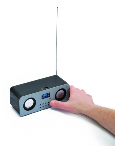
That’s why we had the idea of creating a functional FM radio that you can take anywhere you like.
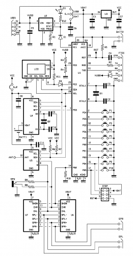
Circuit diagram
Since we wanted to create a modern product we couldn’t do without providing the option for rechargeable batteries for power, allowing to use the device anywhere, with no limitations.
By taking a look at this circuit diagram you will notice there is no power switch, so you can imagine the circuit will never turn off; this is actually the case, because the entire circuit is constantly powered on, and all the stages with considerable power consumption are activated by a key which however doesn’t directly act on power but instead it “notifies” the microcontroller.
Power management for the circuit is in fact completely controlled by software, allowing a series of advantages that will enhance its functioning. For instance, when you activate the MUTE function for the speakers, the entire BF amplifier module is turned off, considerably saving energy. Another absolutely fundamental feature is the possibility to put the whole circuit in power-off mode when the battery voltage goes below a certain threshold, therefore guaranteeing it safeguards. This because Li-po batteries cannot be completely discharged, because below a certain voltage (usually 2.6 V) the battery gets damaged and trying to recharge it might even cause it the battery to burst.
Given this risk, we couldn’t trust the radio user with battery monitoring, therefore we prefer to manage it automatically, within the context of power management.
This is the case for instance with mobile phones and smartphones, that can be easily turned on and off by pressing a key and automatically turn off when the battery reaches the minimum level allowed.
In order to obtain this feature you have to design the entire circuit by carefully taking into consideration current absorption for each device, and also taking into consideration, if necessary, the possibility to set them in low-consumption mode (standby or powerdown mode, in technical lingo). Almost every electronic components commercially available have this mode, which is more and more requested by designers of battery-operated devices, where autonomy is key.
Let’s start from the heart of the project, which is an ATMega328P microcontroller, the same of Arduino, in order to guarantee complete compatibility with the famous programming environment. Most people don’t know that this micro has a sophisticated system that allows to activate or deactivate each single internal peripheral, in order to reach a power-down situation with an absorption of just a few microamps. The microcontroller is surrounded by functional blocks, three of which are found on modules in breakout board format.
Voltage of a completely charged Lipo battery goes up to 4.2 V, which is too much for 3.3V devices, therefore we provided an LDL voltage stabilizer with quiescent current (current dispersed to ground) of just one microamp; in the circuit diagram, the regulator is labeled as U3.
For the radio section, we used an RDA5807M radio module from RDA Microelectronics (labeled U5 in the diagram) which, besides being able to decode RDS signals, it only absorbs 15 µA in powerdown mode (turned off but still powered). The module is very sensitive, it supports 2 de-emphases for stereo decoding (50 and 75 µs) and channel spacing of ±100, ±200, ±50 and just ±25 kHz, implying that it’s input stage is strongly selected.
The RDA5807 module has been to sign for worldwide use and this purpose, it’s RF stage is designed for syncing with any FM frequency all over the world, therefore it can operate from a minimum of 52 to a maximum of 115 MHz.

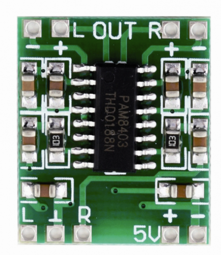
The audio signal outputted by U5 must be amplified, in order to send it to two wideband speakers (we want a stereo your radio, of course…); an additional module on the breakout board can do so, and it is based on the PAM8403 integrated. This is a complete 2-channel amplifier, each channel is a Class D 3+3W, but it does require external low-pass filters and has a guaranteed efficiency of 90%; the chip can work with voltages ranging from 2.5 V to 5 V and it’s been specifically designed to be powered by a USB port or a single set Lipo battery. This integrated circuit has a control pin called shutdown that allows making the module consumes less than one microamp when it is not in use.
Let’s continue the circuit analysis by saying that on our board, we also have an RTC module, which is optional; you can use it for future developments where an appropriate software variant will allow you to turn this project in a radio alarm clock. The RTC module is based on an MCP79410 IC by Microchip and can be fully operational by absorbing just 1.2 µA!
To complete the circuit, we have added the MCP73831 integrated, which takes care of battery recharge when the circuit is connected to a USB port. This integrated circuit, if not powered on, still absorbs the smallest (inverted) current from the battery at around 1µA. taking into account the standby current of Atmega328P, we are still under 40 µA (value conferred by our lap test), that means we will empty a 1000 mAh battery in around 3 years! It is highly probable that the Lipo battery will discharge due to self-discharge, just like any other battery.
A small detail, although maybe not too small: there is no voltage divider for measuring voltage at the battery’s terminals. Knowing the battery’s voltage is crucial in order to know when it is time to turn up the circuit, but we surely cannot use the classic voltage divider; for instance, to 10 kΩ resistors connected in series would absorb around 250 µA, which is more than the rest of the circuit. Our deep knowledge of the Atmega328P microcontroller allowed us to bypass the problem, thanks to the possibility to read power voltage via software and, in fact, the micro is powered by the voltage taken from the battery, unlike the RTC and the radio module, which power is 3.3 V.
In the circuit we have provided a battery box (BATT 1) to possibly power a RTC without main power, although, since the circuit is constantly powered by the main battery, the related function is not crucial, because even if the main battery was completely out of charge, it would still be enough to provide the few microamps necessary to keep the RTC working.
The radio module has a digital volume control which can be easily adjusted through software commands, this allows us to do without the classic potentiometer and use simple buttons.
We have also provided a MUTE feature, which brings volume to zero and deactivates the amplifier module in order to save power, which is useful if you receive a phone call and want to mute the radio.
You will also notice that we have “only” used an 8 MHz quartz for the Atmega328P’s clock, while the standard quartz for the Arduino Uno board is, for instance, 60 MHz. Since we don’t have particular needs in terms of performance, having the microcontroller working at a lower frequency clock gives us the advantage of minor power absorption, which is very important in battery-powered circuits such as our radio.
The whole circuit is powered by a single cell, 1000 mAh Lipo battery; considering that, at moderate volume, circuit absorbs around 45 mA, will be able to listen to music for over 20 hours.
For the recharge, we set our integrated MCP38731 battery charger for a recharge current of around 250 mA, which allows to totally recharge the Lipo battery in around four hours.
On the printed circuit you will also find the ICSP connector for downloading the bootloader and the FTDI connector which is compatible with the FTDI CONVERTITORE USB-SERIALE module by Open Electronics, necessary for uploading this sketch on the microcontroller.
The SJ12 jumper was only needed during the test phase to measure current absorbed by the RTC and the radio module; in fact, you can see that it is connected in series to the Vcc adapter.
The SJ1 three-way jumper has a central contact that can be connected in USB BAT position and allows to choose how to power the circuit, as shown below.
- MODE 1: SJ1’s central contact is closed on the BAT serigraphy side and the circuit is powered by the battery. Connecting a USB cable and/or the FDTI programmer recharges the battery.
- MODE 2: SJ1’s central contact is closed on the USB serigraphy side and the circuit is powered by the USB cable and/or the FDTI programmer. In this mode, battery MUST be removed.
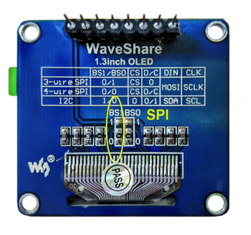
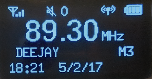
For displaying data we have opted for a modern OLED display with 128 x 64 pixel resolution which, given the construction technology, does not need backlighting, it absorbs a really small power and has a wide angle of vision. Since this is a graphics display, we can use it to visualize letters, numbers and icons; also, visualization is always crisp, which is always a good thing.
Practical assembly
In order to keep our prototype’s profile low we have soldered the display directly on the circuit board with a single 8-way strip connector; 2 small plastic washers are all it takes to keep the display in place on the opposite side from the connector; anyways, the circuit board has holes for screw-on placement. In our prototype, we have soldered the display directly using a strip connector in order to leave a 3 mm gap between display and the circuit board. The PAM8403 comes preassembled in a breakout of different formats, therefore the print board has been designed to accept the major formats available on the market.
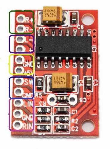
The breakout in the Open Electronics catalog (code PAM8403POT, shown in figure) is compatible with connector labeled U7, however, in order to use it we must remove the potentiometer (which is not easy) and bring the shutdown lead outside with a wire.

The breakout board we have used, which is also sold by Open Electronics with code MICROAMPLID2X3W is compatible with the connector labeled U8 and has no potentiometer;
it is therefore necessary to make the shutdown pin available, which is not really hard to do, however you, must use great care in doing it. First things first, you have to cut off the track connecting pins 12 and 13; then, make two small holes on the printed circuit between pin “+” and pin “R”: now solder a 2,54 7-pole male strip connector. Now, solder a small segment of wire which will connect pin 12 of the PAM8403 integrated with the strip’s pin, as shown in figure .
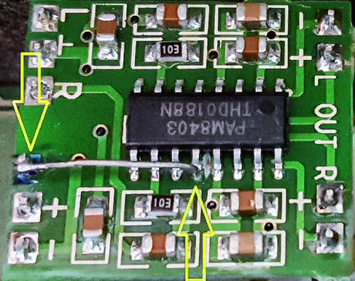
In the end, pin 12 (Shutdown) of the PAM8403 integrated must be connected to pin 7 of the U8 connector. To make things easier, you can also connect to small strips by applying that on the output leads to which the speakers would be connected to.
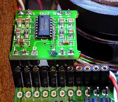
In figure you can see the 2846-MICROAMPLID2X3W breakout board mounted on our board.
For further information, please note that there is another breakout board which is compatible with U8 connector, already equipped with shutdown pin on the connection pads; however, you have to remove the small pull-up resistor that would always keep the module active.
The antenna can be created using a simple 75 cm wire segment (1/4 wavelength at FM means frequency…) or you can use a telescopic antenna from an old FM radio receiver or a radio control receiver.
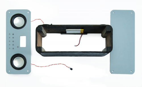
As mentioned before, our circuit can be powered with a 1000 mAh single cell Lipo battery, you just have to place it on the bottom of the container with hot glue.
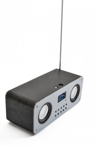
The ideal speakers for this project, that you can see in the prototype photo, are sold by Open Electronics with code 2846-AP5243W (you’re going to need 2); these are well-built, inverted dome transducers with 52 mm diameter, capable of sustaining power up to 3 W. They have a generously-sized magnet that allows high-efficiency and therefore a high-quality audio output even at small power. They also have a good frequency response, so our radio will perform as a compact stereo system.
Operation
The first operation to carry out after the circuit board is ready is to install the bootloader. For this operation you will need an Arduino board to use as programmer; besides, remove all the jumpers and battery and connect OpenRadio to the Arduino board by following the connections listed in Table 1.
Table1
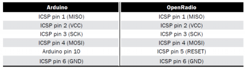
Open Arduino’s IDE and upload ArduinoISP sketch (with programmer function) on the Arduino board, then set “Arduino Pro or Pro Mini” as target and ATmega 328 (3,3V, 8 MHz)” as processor. Set Arduino as programmer with the command Tools – Programmer: “Arduino as ISP-2, then launch the bootloader write using the command Tools-Write the boot loader. In our case, the procedure returned an error with version 1.6.10 while it was completed successfully with version 1.0.5 of Arduno’s IDE. Once the bootloader is installed, OpenRadio becomes an Arduino compatible board for all practical purposes, provided you set board to type on “Arduino Pro o Pro Mini” with “ATmega 328 (3,3V, 8MHz)” as processor.
Before uploading the OpenRadio’s sketch you have to install the additional libraries used in the project. In the list you can find their name and link for the download, however, in order to avoid possible incompatibilities, they are also available along with the file from this project which can be downloaded from the magazine’s website.
We called for the compiler, during the sketch compiling phase, to automatically read date and time from the PC and consequently sync with OpenRadio.
The first time you upload the sketch you have to remove the comment from the line setDataTime() which is necessary to set date and time of the RTC module, then, you will not have to update the clock any longer in order to upload other sketch variants and this line can be commented.
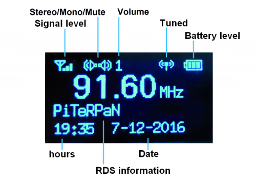
The display can provide many information, starting from the main ones such as battery level all the way up to synch frequency but also signal power, Mono/Stereo functioning mode and can also tell if the radio is perfectly in tune, in the bottom section time and date is kept updated by the RTC module. To this purpose, see in figure.
It looks like there are a lot of buttons but actually five of them are used to recall save the radio stations, besides, some have a dual functionality based on long press or short press, you can see a recap of their features in Table 2.
Table2
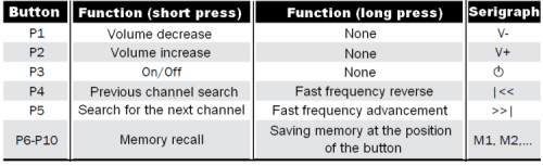
In order to assign advanced features to the keys we use the Button library by Jack Christensen, because it has some advanced features that cannot be found in other libraries; pay attention because there are other libraries named Button, however with different implemented features.
This library allows to detect is a moment in which the button is pressed and when it is released, generating two separate events; furthermore, it can detect button long press.
By combining these events you can have the program execute two separate functions, based on the button being short pressed or long pressed. It is understood that the instant in which the button is pressed is not used to carry out any functions because in that moment we still don’t know how long the button will be pressed for. This advanced feature has been used to manage synchronization that can be made using the SEEK function, which search for the next radio station and synchronizes it or the FAST FORWARD function that allows the frequency to rapidly go forward, which is useful for instance if you are searching for a radio station with a very different frequency from the current one.
Memory managing (PRESET) is also handled in advanced mode: by short pressing the button you can recall the corresponding radio station saved, while pressing the button allows to save the current frequency into specific position. The volume button allows to also carry out the MUTE function and shut down the amplifier module thus leaving the speakers completely silent.
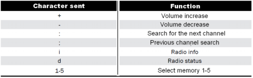
If you leave the board connected to a personal computer, besides debug messages you will also be able to control it through Arduino’s Serial Monitor: all you have to do is open communication session and set a data transfer speed of 9600 bauds.
The implemented commands for this purpose are reported in Table 3.
Table3
Conclusion
In this article we have proposed a high-quality, portable, self-powered FM radio receiver which can be possibly equipped with a clock in order to turn it into a radio alarm clock; we have used advanced hardware and, in order to simplify the project and reduce the electronics encumbrance, we have mounted specific modules on the microcontroller board for the radio receiver, the display and BF amplifier, which description you can use at starting point for new developments. With that said, we hope you enjoyed the project and most of all enjoy your music!
From Openstore
87.6-108 MHz Stereo FM Radio Module
Charge regulator for LiPo – SMD
ATMEGA328-AU – Microcontrollore ATMEGA328

Hi, perhaps I am missing it, but is there a download link for the firmware? Thanks!
Hello,
Nice project. Where do I find the software for this radio ?
Thank you,
Joost.
Very good project, but the sketch is missing. Where can I find “OpenRadio’s sketch.
Thanks,
Cezar
Very good project, but the sketch is missing. Where can I find “OpenRadio’s sketch”.
Thanks,
Cezar
Very good project, but the sketch is missing. Where can I find “OpenRadio’s sketch”.
Thanks,
Cezar