

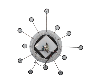
IKEA’s Figgjo, is designed to be a mirror, but with a little ‘electronic can becomes fascinating light equipped wall clock.
It’s a round mirror, from which twelve evenly spaced rays and this makes it perfect for a clock base.
The twelve rays with small round mirrors will be our hours, while the circumference of our mirror will be tracking seconds and minutes, thanks to colored LEDs lighted up as a continuous strip and as a single element (respectively for seconds and minutes).
Strips and LED
We will use LED strips based on HL1606 controller, with two type 5050 RGB SMDs each chip and 32 LEDs per meter. The 30 LEDs strip is less than one meter: you can “roll” it on a circumference of about 30 cm in diameter that can be hidden behind the mirror.
We will only use 30 LEDs to indicate the minutes and seconds, using points and lines to differentiate. We’ll be leaving the colours to be randomly generated.
The RTC shield
There are various ways to create an Arduino based clock: the most simple is using the RTCSHIELD. This is based on Maxim-Dallas DS1307, which is a Real Time Clock capable of freeing the CPU from keeping up with time management. Information about time and date are transferred to the Arduino microcontroller via the I²C-bus.
The bus is attachd to pins numbered 5 (SDA) and 6 (SCL) that match with Arduino’s SCL and SDA pins (UnoRev3 and MegaRev3), which acts as a master unit of the I²C bus, while the DS1307 is the slave.
In previous Arduino versions (such as UnoRev2 or Arduino2009), the SCL and SDA signals are available on pins A4 and A5, to make the shield also compatible with these versions, there’s some soldering toyou’ll need to do.
The project takes shape

Let’s summarize: we need an IKEA Figgjo mirror, one meter of a RGB LED smart strip with 30 LEDs – that will be driven thanks to three SPI data lines – a RTC shield that takes care of time to be driven thanks I²C, and a dozen LED to mark the hours by illuminating each of the twelve small mirrors.
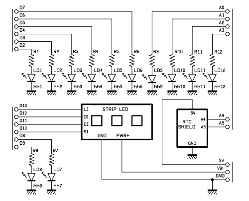
To keep it simple, we will not do any multiplexing: hours LEDs will be connected directly to the Arduino’s pins ranging ftom D2 to D9, then we’ll be using four pins that are usually dedicated analog input (A0 to A3); those will be reconfigured as digital outputs through pinMode command.
To drive the LED strip with SPI we’ll use pins D10, D11 and D12.
The LEDs in charge of showing the hours have the cathode to ground and the anode connected to an Arduino pin as follows:
D2 = h 1
D3 = h 2
D4 = h 3
D5 = h 4
D6 = h 5
D7 = h 6
D8 = h 7
D9 = h 8
A0 = h 9
A1 = h 10
A2 = h 11
A3 = h 12
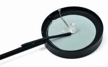
In theory we have to carry two wires for each LED, and remind also to insert a current limiting resistor, but Figgjo’s structure comes handy in this case. As the structure is conductive, we can use it as a mass and bring only one wire to the LEDs, since the cathode can be welded directly to the structure itself.
From the LED strip instead we have five wires as per the following:
L in
C in
D in
S in
Gnd
Observing the strip will also notice the presence of a sixth connection, +5V, to which, however, a supply wire is soldered to an outlet of round type, with central positive.
These strips have their own connection mode: the output from the previous LED block of two LEDs overlooks each pitch and in case the strip is cut from a longer piece, Arduino must be connected to the pins marked with the “I” (inputs) while the pins marked with “O” are the outputs.
Each chip acts as a shift register that sends the data in its memory to the following, every time it receives new. The clock signal manages the transfers timing, while the pin which is not connected with “S” shall be used as a step signal to activate the fade in and fade out modes provided by the HL 1606 chip. This is based on PWM, where for each impulse on S there is an increase or decrease of the intensity with which the PWM which enables the LED. This system allows for the synchronization of the shades over the entire strip in a definite and repeatable fashion, but makes programming of the strip itself a bit more complex.
A wiring
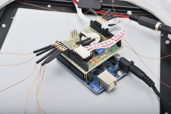
As we have seen thus far, apart from the RTC shield, the rest of the composition is based on wires and connections. We wanted to propose an assembly based on the direct connection of the resistors to the insulated wire that leads to each LED, while the other end can be inserted directly into the pinstrip hole corresponding to the signal to be used.
From the picture you can see how practical and fast this is. Note that to be able to solder the cathode behind each mirror you need to scratch the surface to remove anti rust powder and epoxy resin.
The current limiting resistor refers to blue LEDs; to limit the current to approximately 15 mA, given the 5V supplied from Arduino, a 82 ohms resistor is to be used. If you use LEDs of other colors, remember to recalculate it not to exceed the 15 mA current.
Now that the 12 LED for the hours are connected, we can proceed with the wiring of the LED strip, already cut to length.
The positive of the 5V supplied to the circuit, is also to be sent to the Arduino using a piece of insulated wire which starts from the round socket strip LED (central pin, which corresponds to the positive) and arrives to Arduino’s pinstrip (via the RTC SHIELD) in correspondence of the 5V pin (between GND and 3.3 V). In this case, you’re feeding the microcontroller directly, bypassing the voltage regulators, so pay attention to the power supply you choose.
The sketch
/*
 Ikea Clock
 created 2013
 by Boris Landoni
 http://www.open-electronics.org

 This example code is in the public domain.

*/

#include <Wire.h>
#include "RTClib.h"

RTC_DS1307 RTC;

// HL1606strip is an adaptation of LEDstrip from  http://code.google.com/p/ledstrip/
#include "HL1606strip.h"

// use -any- 3 pins!
#define STRIP_D 12
#define STRIP_C 11
#define STRIP_L 10

// Pin S is not really used in this demo since it doesnt use the built in PWM fade
// The last argument is the number of LEDs in the strip. Each chip has 2 LEDs, and the number
// of chips/LEDs per meter varies so make sure to count them! if you have the wrong number
// the strip will act a little strangely, with the end pixels not showing up the way you like
HL1606strip strip = HL1606strip(STRIP_D, STRIP_L, STRIP_C, 160);

const int h1  =  2;      // hour 1
const int h2  =  3;      // hour 2
const int h3  =  4;      // hour 3
const int h4  =  5;      // hour 4
const int h5  =  6;      // hour 5
const int h6  =  7;      // hour 6
const int h7  =  8;      // hour 7
const int h8  =  9;      // hour 8
const int h9  =  A0;      // hour 9
const int h10 =  A1;      // hour 10
const int h11 =  A2;      // hour 11
const int h12 =  A3;      // hour 12

int hours=0;
int minutes=0;
int seconds=0;
int ledcolor=0;
int mcolor=3;
int scolor=2;
boolean change=0;

boolean randomcolor=1;
boolean sbar=0;
boolean chghour=1; //change the bar/point at new hour

void setup(void) {
  pinMode(h1, OUTPUT);
  pinMode(h2, OUTPUT);
  pinMode(h3, OUTPUT);
  pinMode(h4, OUTPUT);
  pinMode(h5, OUTPUT);
  pinMode(h6, OUTPUT);
  pinMode(h7, OUTPUT);
  pinMode(h8, OUTPUT);
  pinMode(h9, OUTPUT);
  pinMode(h10, OUTPUT);
  pinMode(h11, OUTPUT);
  pinMode(h12, OUTPUT);

  Serial.begin(9600);
    Wire.begin();
    RTC.begin();
	RTC.sqw(1);		//0 Led off - 1 Freq 1Hz - 2 Freq 4096kHz - 3 Freq 8192kHz - 4 Freq 32768kHz
  if (! RTC.isrunning()) {
    Serial.println("Clock regulated");
    // following line sets the RTC to the date & time this sketch was compiled
    RTC.adjust(DateTime(__DATE__, __TIME__));
  }
}

void loop(void) {
   readclock();
   stripOff();
   writeseconds();
   writeminutes();
   writehours();

   delay(200);
}

/**********************************************/

void readclock(){

    DateTime now = RTC.now();
    hours=now.hour();

    if (hours>12) hours=hours-12;

    minutes=now.minute();
    minutes = (minutes/2);

    seconds=now.second();
    seconds = (seconds/2);

    Serial.print(now.hour(), DEC);
    Serial.print(':');
    Serial.print(now.minute(), DEC);
    Serial.print(':');
    Serial.print(now.second(), DEC);
    Serial.println();

    Serial.print(hours, DEC);
    Serial.print(':');
    Serial.print(minutes, DEC);
    Serial.print(':');
    Serial.print(seconds, DEC);
    Serial.println();
    Serial.println();

     if ((now.second()==59)&&(now.minute()==59)&&(chghour==1)){
        if(sbar==1) {
          sbar=0;
        }
        else
        {
          sbar=1;
        }
    }

    if ((now.second()==00)&&(randomcolor==1)&&(change==0)){

      mcolor=color();
      scolor=color();
      while (mcolor==scolor){
            scolor=color();
      }
      change=1;
    }

    if ((now.second())==02) {
      change=0;
    }

 if ((now.second())%2==0){
     strip.writeStrip();
   }

}

void writehours(){
  digitalWrite(h1, LOW);
  digitalWrite(h2, LOW);
  digitalWrite(h3, LOW);
  digitalWrite(h4, LOW);
  digitalWrite(h5, LOW);
  digitalWrite(h6, LOW);
  digitalWrite(h7, LOW);
  digitalWrite(h8, LOW);
  digitalWrite(h9, LOW);
  digitalWrite(h10, LOW);
  digitalWrite(h11, LOW);
  digitalWrite(h12, LOW);
  switch (hours){
    case 1:
      digitalWrite(h1, HIGH);
      break;
    case 2:
      digitalWrite(h2, HIGH);
      break;
    case 3:
      digitalWrite(h3, HIGH);
      break;
    case 4:
      digitalWrite(h4, HIGH);
      break;
    case 5:
      digitalWrite(h5, HIGH);
      break;
    case 6:
      digitalWrite(h6, HIGH);
      break;
    case 7:
      digitalWrite(h7, HIGH);
      break;
    case 8:
      digitalWrite(h8, HIGH);
      break;
    case 9:
      digitalWrite(h9, HIGH);
      break;
    case 10:
      digitalWrite(h10, HIGH);
      break;
    case 11:
      digitalWrite(h11, HIGH);
      break;
    case 12:
      digitalWrite(h12, HIGH);
      break;

   }
}

void writeminutes(){
  strip.setLEDcolor(minutes, mcolor);
}

void writeseconds(){
  if (sbar==1){
      for (int i=0; i <= seconds; i++) {
      strip.setLEDcolor(i, scolor);
      }
  }
  strip.setLEDcolor(seconds, scolor);
}

  // turn everything off (fill with BLACK)
void stripOff(void) {
  // turn all LEDs off!
  for (uint8_t i=0; i < strip.numLEDs(); i++) {
      strip.setLEDcolor(i, BLACK);
  }
  //strip.writeStrip();
}

int color(){

int tmp= random(1,7);
switch (tmp){
  case 1:
    ledcolor= WHITE;
    break;
  case 2:
    ledcolor= RED;
  case 3:
    ledcolor= YELLOW;
    break;
  case 4:
    ledcolor= GREEN;
    break;
  case 5:
    ledcolor= TEAL;
    break;
  case 6:
    ledcolor= BLUE;
    break;
  case 7:
    ledcolor= VIOLET;
    break;
  }

 return(ledcolor);
}
From a conceptual point of view, the program that drives our watch should do very little: to acquire hours, minutes and seconds from the RTC minutes, then divide minutes and seconds by two, and go for visualization.
Visualizing hours means turning the corresponding LED on; the strip turns on gradually to show seconds, while for minutes you turn on a single LED superimposed to the latter, if necessary.
Most of the complexity is in the reading RTC via I2C and in writing data on the LED strip according to the SPI protocol.
Fortunately we are dedicated libraries that almost completely solve both the problems.
The first, called RTClib.h, is dedicated to the RTC. It can be downloaded from this link (note that this is a slightly modified version of the library originally developed by Adafruit).
Thanks to the RTClib all becomes very simple: once you create the clock instance (“RTC_DS1307 RTC”) you can obtain the data thanks to the command “DateTime now = RTC.now()”
With “now.hours”, “now.minutes” and “now.seconds” we directly obtain values for processing, while the special routine using “RTC.isrunning” is key to see if you need to adjust the time.
If the RTC has not yet been set with the “adjust” command, the “IsRunning” returns false (the library reads the “Clock Halt” / 7th bit of the 0x00 register on the DS1307): this leds to the if cycle that uses the compilation timestamp to write the corresponding numeric values – replaced by the IDE at labels compiling time – on the RTC chip as starting values.
With this arrangement, we will have a clock setting very close to that of the host computer on which runs the IDE.
Regarding the strip, we use the HL1606strip.h library, available on http://code.google.com/p / Ledstrip where you just define the pins connected to the Arduino and the number of active LEDs in the strip. The setLEDcolor(position, color) method allows you to define the color of each LED among the eight colors available (black, white, red, yellow, green, blue and purple); writing each LED color and transmitting the info to the strip are two separate functions by the way. Thanks to this, the software can be set to define the color of each LED and then displaying it in different moments.

Toward the bottom of the code, in the color function, there is a missing break; under the red color. :)