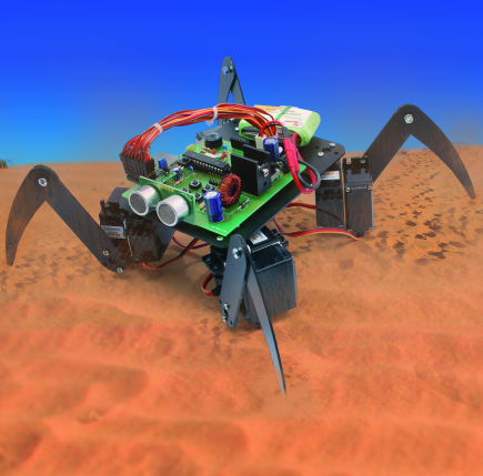
THE ROBOT
This robot has four legs with two degrees of freedom to obtain totally eight degrees of freedom; this is the minimum requirement to be able to form a shape similar to a spider and also to get acceptable movements. This choice obliges to use a controller for eight independent servomotors and it must have some functions to control their positions and speeds. A lot of attention is paid to shapes so that it is possible to avoid challenging solders and bondings which makes it possible to assemble it just using some double stick tape. The chassis of the spider is composed by a base, where servomotors and legs are fixed. In this way the obtained shape is very similar to a spider. Because of the flexibility of the vetronite, an additional part was designed to install under the robot, making it more robust and eliminating dips. It is strongly suggested to make the robot chassis using two coppered sides PCB, in this way all the structure will be stronger. Alternatively, any other lightweight and rigid material like 2mm thick aluminum or 4mm thick plexiglass can be used. It is suggested to paint it in black so that it gets more similar to a spider. The drawings related to the parts of the chassis can be found in the following pages but it is suggested to download them from our website. All the holes represented in the drawings refer to the SERVO209 servomotor model used in this project.

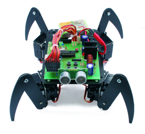
THE MECHANICAL ASSEMBLY

The robot can be assembled following the instructions shown in the drawings and in the pictures of the article. For each leg two servomotors have to be coupled, one is used for rotation movement and the other one is used for lifting and lowering a leg. They can be coupled with double stick tape so that it is possible to easily reuse these servomotors in other projects. Otherwise, it is possible to glue them but a glue optimized for plastic materials has to be used. Complicated software settings for servo motors positioning are not planned so, the maker has to follow the following procedure. First of all, the servomotors have to be taken in the neutral position. It can be done using a servomotor tester or the Spiderin control circuit, because when it turns on, it is programmed to take them to the neutral position. The servomotor arm has to be fixed, through two screws, to the base structure. Robot legs are made by two pieces fixed together by a 3 mm long screw and a nut or alternatively, it is possible to glue them. When the assembly phase is finished, the spider legs must be a little bit higher than the desk surface and the servomotors must be put on the table. The distance between legs must be about 22 cm and each of them has to be orthogonal to the mechanical structure. The PCB can be fixed using some spacers and it is possible to use some clamps for wiring. The ultrasonic sensor is installed on the front part of the robot and in this way, it looks like spider eyes.

THE CONTROL CIRCUIT

The core of the electrical circuit is the PIC18F2550. This was chosen because it can work with a 48 MHz clock and it has a USB module. Through the usage of the USB module and the bootloader, the user is able to program the microcontroller without using a programmer such as a PICkit. The J6 header connector is soldered on the board and it allows to program the PIC using the PICkit 2. The power supply of the control part is based on a linear voltage regulator while, the power supply of the motors and their driver is based on a switching solution. The linear voltage regulator is a LM2940 because it is a low drop out type. It can also work with a small voltage difference between input and output. Alternatively, a LM2937 can be used. The famous LM7805 can be also used but in this case, the power supply voltage must be above 8 V. The described voltage converter is not able to provide all the current requested by the servomotors. The drawn current by the motors is about 3 A. Obviously, the circuit does not consume this amount of current all the time and the requested power supply fluctuates a lot. Because the robot is powered by a battery, it is better to use a switching regulator instead of a linear one, because the efficiency is higher. The LM2576-5 IC in step down configuration is used the way it is possible to power this circuit with a voltage range from 7 to 12 V. It means that it is possible to use 2S, 3S LiPo battery or 8-10 cells NiCd-NiMH battery. In both cases, the user must take care of the weight of the battery. The suggested batteries are AAA NiCd-NiMH or 2S-3S 1000 mA/h LiPo batteries. The prototype was powered by eight cells 800 mA/h NiCd battery and by two cells 860 mA/h LiPo battery. It is also ready to host an MMA7260QT accelerometer. This component is not managed by the firmware but it can be useful for “rough terrain walking experiments”. There is also an SRF05 ultrasonic sensor to detect obstacles. It looks like the spider eyes.

The PNA4602 infrared sensor is used for the remote command. The battery voltage is read by the zeroth analogic channel of the PIC which is connected to a voltage divider composed by R6 and R7. The maximum allowed voltage is 20,48 V. The resolution of the ADC channel is based on 10 bits so the resolution is 20 mV. The minimum required power supply voltage is 6,5 V. Under that voltage the microcontroller turns off all the servomotors to avoid to discharge excessively the battery. This value is optimized for the usage with 2S LiPo or eight cells NiCd battery. If the battery voltage is higher, it is possible to set a different value.
FUNCTIONAL TESTING

Before inserting the PIC and the servo controller, a 100 Ohm resistor must be connected between “+” and “-“ of the J2 connector. Then, the circuit has to be powered on and the voltage (5 V) has to be checked on the PIC side and on the output of the switching power supply. The led LD2 has to be powered on. After that, it is possible to insert the previously programmed PIC and the servo controller. About one second after the start up of the circuit, all the servomotors move to the neutral position. Some servomotors may slightly vibrate because they fluctuate very close to the neutral point. In this case, a small “hit” can make the mechanism put in the neutral position.
THE FIRMWARE
The PIC firmware, developed with PicBasic- Pro compiler, manages devices and the servo controller. During the startup, the program sets all the necessary internal registers in particular the ones related to the USART module. This module is used to send and receive commands using the infrared remote command. The reception is managed through the usage of interrupts and it works at 1200 baud. Because of this, the PIC is not able to manage the MSSC module through the USART module. The MSSC is managed through the software command “SEROUT” at 9600 baud.
The servomotors used in this project have to be managed with 50 pulses per second. The variable period of these pulses (PWM modulation) allows to define the servo position. The robot hosts eight servomotors so, for each second, it is necessary to calculate eight different pulses. Because of that, just one microcontroller is not enough. Infact, it is suggested to calculate positions and then to send them to another PIC that calculates and generates pulses for the servomotors. The MSSC module also allows to set the speed for reaching a desired position so, it is possible to create movements with different speeds. This feature is available because the advanced function (Pololu mode) is enabled. If the “protocol selection jumper” is shorted, the Mini SSC II mode is activated. This function just manages the immediate positioning of the servos. The servomotor driver works with a RS-232 link manageable by a PIC. The most advanced functional mode (the Pololu mode) allows to manage each servo according to an internal variable value. Its range is between 500 and 5500 and it has 0,5 us resolution. The position can be indicated in an absolute way or related to a neutral point. The baudrate is automatically recognized by the module and it must be between 2000 and 40000 baud. The communication protocol works with five or six bytes. The first one is needed for the synchronization and its value is 80h (128d). The second one is the device address and its value is 01h. The other bytes are related to commands and values (see the following table). In each byte the first bit value must be zero.
What follows is a list of all possible commands to send by the instruction “SEROUT”.
COMMAND 0
This command defines the scale of the desired position, the movement direction and the state of the servo (on or off). The command is composed by eight bits. The first one defines the scale of the desired position. The firmware works with a range between 0 and 127 with the 63 neutral point. In this case this value must be set to 15, where a seven bits variable matches to a 90° movement. If the position value is higher than 63 (neutral value), the direction gets set in a way to move forward and to rotate it in a way to make the robot stand up. The servo off function turns off the corresponding motor and it is used to limit the current consumption when the battery is too low. The command syntax is: “SEROUT LS0,2,[$80,$01,$00,0,$6F]” and it must be sent to all servomotors modifying the second from last byte with the value of the servo which has to be moved.
COMMAND 1
This command allows to set the movement speed of the servomotors. If the value of this command is zero, the servomotor tries to reach the requested position as fast as possible, otherwise, the estimated necessary time to reach the desired position can be calculated using this formula: Tmove =(Starting_point – Final_point)*150/speed [ms]. The command syntax is “SEROUT LS0,2,[$80,$01,$01,0,speed]“and it must be sent to all present servomotors.
COMMAND 2
This command allows to set the desired position of the servomotors. The command syntax is “SEROUT LS0,2,[$80,$01,$02,0,pos]”. The value of the “pos” variable represents the requested position to reach and it has to merge to the scale previously set. The value 63 sets the servo in the middle while, with the values 0 and 127 the servo- rotates respectively from -45° to +45°.
THE SERVO MOVEMENTS
There are two different “walking styles” for Spiderin but generally, at every moment, there must be some legs standing on the ground and pushing forward while, the other remaining legs stand up and re-position. In the first walking style firstly, two legs push the robot forward while the other two re-position. Then, these movements will invert. This walking style expects just two support points so, the static balance is not guaranteed, however, taking care of inertia and center of gravity, it works quite well. In the picture this walking style is described: blue arrows indicate movements of the low standing legs (standing on the ground) while red arrows indicate movements of the raised legs (raised from ground).

The second walking style expects three legs standing on the ground and a moving one. In this way every step is composed by four phases. This walking style allows a greater stability. It is possible to get the best result if the frame is rigid and the center of gravity remains in the triangle formed by the three legs. To get a greater stability it is suggested to keep legs opened wilder instead of being too close. For each step, every servomotor rotates “alpha” degrees.

The correspondence between the firmware and the movements is shown in this table:

This walking style is described in this table:

During every step taken by the robot, the legs (standing on the ground) make short moves. Because of that, this walking style works only if the surface is smooth.

The ultrasonic sensor is used for detecting obstacles in a distance lower than 30 cm. If it detects an obstacle, the robot stops the forward movement. This sensor is not used in rotation movements. It can be omitted by the firmware and the robot still works. However, it increases the movement autonomy of the Spiderin.
THE PROGRAMMING

For making it easier to everybody to program and develop this robot, it is possible to get access to the PIC through the USB. The PIC has to be pre-programmed with a small program able to manage the USB communication for transferring incoming data directly to the PIC’s memory and it is hosted in the top part of the PIC program memory. This program is usually called bootloader and it is possible to find it in many devices like mobile phones, GPS navigators and everything that allows to upload the firmware without using external programmers. The PIC used in the project is already burnt with the bootloader so it is possible to upload the robot firmware through USB. Through the usage of PICBASICPRO IDE (Integrated development environment), the developer is able to modify the program or just to study it. In PICBASICPRO IDE, the usage of the bootloader must be indicated in the program with these following code lines:
DEFINE LOADER_USED 1
DEFINE RESET_ORG 1000h
The software HID BoolLoader.exe, available with the files related to this project, has to be installed. This small program and the bootloader (HID Bootloader – PIC18F2550) are available to download on the Microchip website. To program the robot, the user has to turn on the robot and to connect it through a USB cable to the PC. Then the user has to press the reset button, release it, and then press the P1 button. The operating system beeps one time when it detects a new connected device and also the software highlights it.

The compiled firmware (.HEX extension) has to be uploaded on the program and through the command “Programma” the PIC is burnt. Then, the user has to press the software “Reset” or to press the reset button on the board. It is seen that it is easier to program the PIC with the bootloader rather than using an external programmer.
THE REMOTE COMMAND

The main functions of the robot can be directly managed through the buttons on the board. It is possible to see these functions on the table nr. 2. “Mode1” is the walking style with three support points and “mode2” is the walking style with two support points, while the rotation movement is always with two support points. The robot can be also managed through an infrared remote command with seven buttons. The sensor installed on the robot and used for receiving commands is called PNA4602 and it works at 38 kHz. The commands are sent with a speed of 1200 baud and they are composed just by a byte. The value of the byte must correspond to the available commands. If the robot receives the signal, the buzzer beeps shortly and if the robot decodes the signal correctly, it executes the received command.

From OpenStore
Spiderin with Arduino
