- makeITcircular 2024 content launched – Part of Maker Faire Rome 2024Posted 2 weeks ago
- Application For Maker Faire Rome 2024: Deadline June 20thPosted 2 months ago
- Building a 3D Digital Clock with ArduinoPosted 7 months ago
- Creating a controller for Minecraft with realistic body movements using ArduinoPosted 7 months ago
- Snowflake with ArduinoPosted 8 months ago
- Holographic Christmas TreePosted 8 months ago
- Segstick: Build Your Own Self-Balancing Vehicle in Just 2 Days with ArduinoPosted 8 months ago
- ZSWatch: An Open-Source Smartwatch Project Based on the Zephyr Operating SystemPosted 9 months ago
- What is IoT and which devices to usePosted 9 months ago
- Maker Faire Rome Unveils Thrilling “Padel Smash Future” Pavilion for Sports EnthusiastsPosted 10 months ago
Spherebot Reloaded: Customize Your Xmas
Let’s create a plotter to decorate Christmas Tree balls with writing and drawings.
Christmas is coming you dusted off your xmas tree and decorated it: everybody try to make it different, buying new decorations and balls of different colors. Well, if you are looking for something original, think of making your personalized balls with drawings and writings at will.
Here comes this machine: a printer, or better to say a plotter, which will draw with a marker on spheres at will, derived from models transformed into G-code files. The machine is easily doable with a few 3D printable pieces (we’ll provide the relative models in a special Thingiverse page) and a control board which is the same of the 3Drag. A computer will be needed for the appropriate printing software.

A bit of history
The machine that we aim to realize is known in the internet world as Eggbot or Spherebot. The first (which takes its name from the fact that it was born to draw and write on eggs) is one is the famous creation of Evil Mad Scientist that also made all the project opensource (see http://egg-bot.com/). The suggested control board (http://www.schmalzhaus.com/EBB/) is based on a Microchip microcontroller, thus many makers have striven trying to realize something similar based on Arduino, because, however good, the Microchip hardware can not rely on the same amount of information exchange and community. The result is a version of the printer that has taken the name of Spherebot and which substantially shares the mechanical structure of the EggBot but differs in the electronics.
Unfortunately, the documentation of this creation is quite fragmented, sometimes incomplete and often outdated: the firmware available did not work, for example, with the latest versions of the Arduino IDE. This is the reason that prompted us to review the entire project trying to create guidelines that would allow anyone to make their own Spherebot.
The printer are based on a system of ball grips that rotate the ball (egg) and on a servomotor mounted on a carriage that drives the pen: the servomotor lifts the pen when not required to write and lowers it when must draw; the gripping system relies on a kind of clamp that locks the ball by two rubber suckers and makes it rotate (by a stepper motor) at a constant speed, in synchronization with the pen movement. The pen is guided by a second stepper motor. To draw lettering and designs, the pen, once the servomotor has let it descend until the tip touches the ball, moves laterally, while the gripping system rotates in one direction or another, so as to create the vertical line.
Our machine
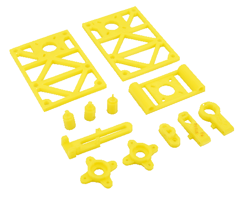
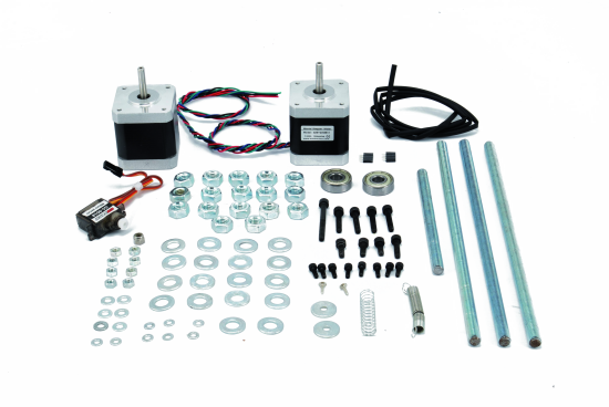
The mechanics of the plotter that we propose is similar to that of the mentioned machines and consists of pieces made with a 3D printer (you can find the models in a separate page of Thingverse, some threaded rods and a couple of ball bearings; in this page you will find the complete list of the parts that compose it.
Compared to the versions available on the Internet, our Spherebot shows a greater “printing area”, so we can also draw on Christmas balls with a bigger diameter of 6÷7 cm.
Software
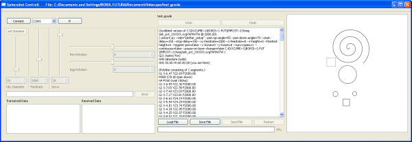
As most of the numerical control machines also our Spherebot is able to manage the G-code. To pass them to the machine you must use a special software.
This software can be downloaded from Github, from the web page https://github.com/thunderbug1/Spherebot-Host-GUI, which has a convenient user interface. The software is very intuitive and also allows you to move all three engines to properly position the marker.
Obtain the Gcode file
To print the Christmas tree balls with our version of Spherebot, you need to turn your ideas into prints, is therefore necessary to go through a simple conversion software, that can transform into G-code your design or text.
Let’s start again with a completely free software: Inkscape. You can download it from http://inkscape.org/en. Inkscape is a vector drawing software based on Scalable Vector Graphics (SVG) format.
Inkscape can import different kind of files of various types and, thanks to a special extension, export our vector drawings in Gcode. This is achieved precisely by the plugin downloadable and available on the Github page https://github.com/martymcguire/inkscape-unicorn.
Installation is easy: just copy the files located in the SRC folder of the downloaded ZIP under Inkscape extensions folder, which by default is C:\Program Files\Inkscape\share\extensions; complete the procedure by restarting Inkscape.
Online you will find many tutorials to learn how to use Inkscape, here we will show you how to transform the writings in Gcode in order to be able to add them to your Christmas decorations. First of all you need to define a correct working area in order to realize if the word has the right size. To do this, from the File menu, choose Document Properties. Here you will find several standard formats available. Our Christmas ball is not exactly standard, hence we define a custom size, such as 10 cm x 5 cm (Fig.3).
Now, with the text tool (selectable with F8 key), type your text by selecting the character you like. In order to be correctly drawn the text should be rotated 180 degrees, thus select it with the tool Select and transforms objects (F1) and from the menu, Object click twice on the item Rotate 90 clockwise. Center the writing in the page and eventually resize it using the appropriate anchors (Fig.6).
Now we have to create the route that our marker must follow in order to create the writing. Pick the item from object to route from the Route menu (Fig.7).
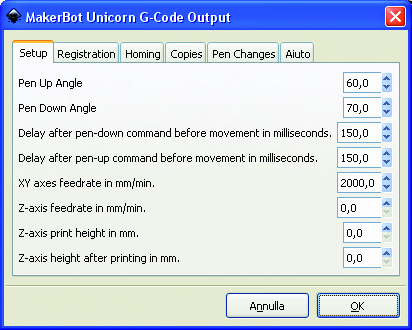
Now there is nothing left than save in Gcode.
A will prompt you to define some parameters such as the speed of execution, the angle that defines the marker raised, lowered, and other parameters that we recommend to copy from the figures that we report (Fig.4 and Fig .5).
Electronics
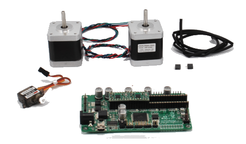
Our Spherebot is made of two stepper motors and a servomotor; as mentioned, a motor serves to rotate the ball on the axis, while the second motor allows to move the marker around the circumference of the sphere. The servomotor is used to raise and lower the pen. To allow anyone to easily edit the software without the need for programmers or compilers a bit of Arduino would be ideal.
So that’s it! The 3Drag printer controlled make by us: in fact this control board is based on ATmega2560 (the same microcontroller of Arduino MEGA) and is able to drive up to 4 stepper motors.
We assemble, in this case, only 2 drivers and we use only the motors provided for the X and Y axes, the first to drive the ball rotation on the axis and the second to move the pen. To the servo instead we use the pins provided for the end-stop. In fact, these pins provide for male strip where you can attach easily to the servo connector.
The only change to be made is to close the bridge that allows you to bring the 5V on the strip.
The firmware
Since the3Drag hardware is used to control a machine with a different function from that expected, it is clear that a specific firmware must be loaded into the ATmega 2560 . This will govern the two stepper-motor and the servo commander. Being an open source project, we had to write all the code, but it was enough to find someone who worked on it and make the changes.
A big hand was given us by Eberhard Rensch http://pleasantsoftware.com/developer/3d
However to let the sketch work with the latest Arduino IDE (version 1.0 above) we had to change it a bit.
The sketch deals directly with the two stepper motors and the servo according to the GCode commands received via the USB port. The combination of the three engines allows you to write on the ball without problems.
Chose the board, modify the sketch and you’ll only need to connect it to the USB port of the PC and upload the firmware.
/*
 * Copyright 2011 by Eberhard Rensch <http://pleasantsoftware.com/developer/3d>
 *
 * This program is free software: you can redistribute it and/or modify
 * it under the terms of the GNU General Public License as published by
 * the Free Software Foundation, either version 3 of the License, or
 * (at your option) any later version.
 *
 * This program is distributed in the hope that it will be useful,
 * but WITHOUT ANY WARRANTY; without even the implied warranty of
 * MERCHANTABILITY or FITNESS FOR A PARTICULAR PURPOSE.  See the
 * GNU General Public License for more details.
 *
 * You should have received a copy of the GNU General Public License
 * along with this program.  If not, see <http://www.gnu.org/licenses/>
 *
 * Part of this code is based on/inspired by the Helium Frog Delta Robot Firmware
 * by Martin Price <http://www.HeliumFrog.com>
 *
 * !!!!!!!!
 * This sketch needs the following non-standard libraries (install them in the Arduino library directory):
 * SoftwareServo: http://www.arduino.cc/playground/ComponentLib/Servo
 * TimerOne: http://www.arduino.cc/playground/Code/Timer1
 * !!!!!!!!
 * Servo up/down velocity Modified by Boris 11/12/13
 */

#include <TimerOne.h>
#include <SoftwareServo.h>
#include "StepperModel.h"

#define TIMER_DELAY 64

/*
 * PINS
 */

   /*  ms1  |  ms2
    ----------------
      L    |  L        ->  Full Step
      H    |  L        ->  Half Step
      L    |  H        ->  Quarter Step
      H    |  H        ->  Sixteenth Step
  */

#define XAXIS_DIR_PIN 55
#define XAXIS_STEP_PIN 54
#define XAXIS_ENABLE_PIN 38
#define XAXIS_ENDSTOP_PIN -1

#define YAXIS_DIR_PIN 61
#define YAXIS_STEP_PIN 60
#define YAXIS_ENABLE_PIN 56
#define YAXIS_ENDSTOP_PIN -1 // <0 0> No Endstop!

#define SERVO_PIN 3

/*
 * Other Configuration
 */

#define DEFAULT_PEN_UP_POSITION 50
#define XAXIS_MIN_STEPCOUNT -5.6*230000
#define XAXIS_MAX_STEPCOUNT 5*230000
#define DEFAULT_ZOOM_FACTOR 0.60 // With a Zoom-Faktor of .65, I can print gcode for Makerbot Unicorn without changes.
                               // The zoom factor can be also manipulated by the propretiary code M402

/* --------- */

StepperModel xAxisStepper(XAXIS_DIR_PIN, XAXIS_STEP_PIN, XAXIS_ENABLE_PIN, XAXIS_ENDSTOP_PIN,
        XAXIS_MIN_STEPCOUNT, XAXIS_MAX_STEPCOUNT, 200.0, 16);
StepperModel rotationStepper(YAXIS_DIR_PIN, YAXIS_STEP_PIN, YAXIS_ENABLE_PIN, YAXIS_ENDSTOP_PIN,
        0, 0, 200.0, 16);

SoftwareServo servo;
boolean servoEnabled=true;

long intervals=0;
volatile long intervals_remaining=0;
volatile boolean isRunning=false;
int servovalue=DEFAULT_PEN_UP_POSITION;

// comm variables
const int MAX_CMD_SIZE = 256;
char buffer[MAX_CMD_SIZE]; // buffer for serial commands
char serial_char; // value for each byte read in from serial comms
int serial_count = 0; // current length of command
char *strchr_pointer; // just a pointer to find chars in the cmd string like X, Y, Z, E, etc
boolean comment_mode = false;
// end comm variables

// GCode States
double currentOffsetX = 0.;
double currentOffsetY = 0.;
boolean absoluteMode = true;
double feedrate = 300.; // mm/minute
double zoom = DEFAULT_ZOOM_FACTOR;

const double maxFeedrate = 2000.;
// ------

void setup()
{
    Serial.begin(115200);
    Serial.print("SphereBot modified By Boris Landoni 1.0\n");

    clear_buffer();

    servo.attach(SERVO_PIN);
    servo.write(DEFAULT_PEN_UP_POSITION);

    if(servoEnabled)
    {
      for(int i=0;i<100;i++)
      {
          SoftwareServo::refresh();
          delay(4);
      }
    }

    //--- Activate the PWM timer
    Timer1.initialize(TIMER_DELAY); // Timer for updating pwm pins
    Timer1.attachInterrupt(doInterrupt);

#ifdef AUTO_HOMING
    xAxisStepper.autoHoming();
    xAxisStepper.setTargetPosition(0.);
    commitSteppers(maxFeedrate);
    delay(2000);
    xAxisStepper.enableStepper(false);
#endif
}

void loop() // input loop, looks for manual input and then checks to see if and serial commands are coming in
{
  get_command(); // check for Gcodes
  if(servoEnabled)
    SoftwareServo::refresh();
}

//--- Interrupt-Routine: Move the steppers
void doInterrupt()
{
  if(isRunning)
  {
      if (intervals_remaining-- == 0)
	 isRunning = false;
      else
      {
          rotationStepper.doStep(intervals);
          xAxisStepper.doStep(intervals);
      }
  }
}

void commitSteppers(double speedrate)
{
  long deltaStepsX = xAxisStepper.delta;
  if(deltaStepsX != 0L)
  {
    xAxisStepper.enableStepper(true);
  }

  long deltaStepsY = rotationStepper.delta;
  if(deltaStepsY != 0L)
  {
    rotationStepper.enableStepper(true);
  }
  long masterSteps = (deltaStepsX>deltaStepsY)?deltaStepsX:deltaStepsY;

  double deltaDistanceX = xAxisStepper.targetPosition-xAxisStepper.getCurrentPosition();
  double deltaDistanceY = rotationStepper.targetPosition-rotationStepper.getCurrentPosition();

  // how long is our line length?
  double distance = sqrt(deltaDistanceX*deltaDistanceX+deltaDistanceY*deltaDistanceY);

  // compute number of intervals for this move
  double sub1 = (60000.* distance / speedrate);
  double sub2 = sub1 * 1000.;
  intervals = (long)sub2/TIMER_DELAY;

  intervals_remaining = intervals;
  const long negative_half_interval = -intervals / 2;

  rotationStepper.counter = negative_half_interval;
  xAxisStepper.counter = negative_half_interval;

//  Serial.print("Speedrate:");
//  Serial.print(speedrate, 6);
//  Serial.print(" dX:");
//  Serial.print(deltaStepsX);
//  Serial.print(" dY:");
//  Serial.print(deltaStepsY);
//  Serial.print(" masterSteps:");
//  Serial.print(masterSteps);
//  Serial.print(" dDistX:");
//  Serial.print(deltaDistanceX);
//  Serial.print(" dDistY:");
//  Serial.print(deltaDistanceY);
//  Serial.print(" distance:");
//  Serial.print(distance);
//  Serial.print(" sub1:");
//  Serial.print(sub1, 6);
//  Serial.print(" sub2:");
//  Serial.print(sub2, 6);
//  Serial.print(" intervals:");
//  Serial.print(intervals);
//  Serial.print(" negative_half_interval:");
//  Serial.println(negative_half_interval);
//  Serial.print("Y currentStepCount:");
//  Serial.print(rotationStepper.currentStepcount);
//  Serial.print(" targetStepCount:");
//  Serial.println(rotationStepper.targetStepcount);

  isRunning=true;
}

void get_command() // gets commands from serial connection and then calls up subsequent functions to deal with them
{
  if (!isRunning && Serial.available() > 0) // each time we see something
  {
    serial_char = Serial.read(); // read individual byte from serial connection

    if (serial_char == '\n' || serial_char == '\r') // end of a command character
    {
      buffer[serial_count]=0;
      process_commands(buffer, serial_count);
      clear_buffer();
      comment_mode = false; // reset comment mode before each new command is processed
      //Serial.write("process: command");
    }
    else // not end of command
    {
      if (serial_char == ';' || serial_char == '(') // semicolon signifies start of comment
      {
        comment_mode = true;
      }

      if (comment_mode != true) // ignore if a comment has started
      {
        buffer[serial_count] = serial_char; // add byte to buffer string
        serial_count++;
        if (serial_count > MAX_CMD_SIZE) // overflow, dump and restart
        {
          clear_buffer();
          Serial.flush();
        }
      }
      else
      {
      }
    }
  }
}

void clear_buffer() // empties command buffer from serial connection
{
  serial_count = 0; // reset buffer placement
}

boolean getValue(char key, char command[], double* value)
{
  // find key parameter
  strchr_pointer = strchr(buffer, key);
  if (strchr_pointer != NULL) // We found a key value
  {
    *value = (double)strtod(&command[strchr_pointer - command + 1], NULL);
    return true;
  }
  return false;
}

void check_for_version_controll(char command)
{
  if(command == 'v')
  {
    Serial.print("EBB 1.0\n");
  }
}

void process_commands(char command[], int command_length) // deals with standardized input from serial connection
{
  if(command_length == 1)
  {
    check_for_version_controll(command[0]);
  }
  if (command_length>0 && command[0] == 'G') // G code
  {
    //Serial.print("proces G: \n");
    int codenum = (int)strtod(&command[1], NULL);

    double tempX = xAxisStepper.getCurrentPosition();
    double tempY = rotationStepper.getCurrentPosition();

    double xVal;
    boolean hasXVal = getValue('X', command, &xVal);
    if(hasXVal) xVal*=zoom*1.71/2;                              //this factor is for correction to meet the unicorn coordinates
    double yVal;
    boolean hasYVal = getValue('Y', command, &yVal);
    if(hasYVal) yVal*=zoom;
    double iVal;
    boolean hasIVal = getValue('I', command, &iVal);
    if(hasIVal) iVal*=zoom;
    double jVal;
    boolean hasJVal = getValue('J', command, &jVal);
    if(hasJVal) jVal*=zoom;
    double rVal;
    boolean hasRVal = getValue('R', command, &rVal);
    if(hasRVal) rVal*=zoom;
    double pVal;
    boolean hasPVal = getValue('P', command, &pVal);

    getValue('F', command, &feedrate);

    xVal+=currentOffsetX;
    yVal+=currentOffsetY;

    if(absoluteMode)
    {
      if(hasXVal)
        tempX=xVal;
      if(hasYVal)
        tempY=yVal;
    }
    else
    {
      if(hasXVal)
        tempX+=xVal;
      if(hasYVal)
        tempY+=yVal;
    }

    switch(codenum)
    {
      case 0: // G0, Rapid positioning
        xAxisStepper.setTargetPosition(tempX);
        rotationStepper.setTargetPosition(tempY);
        commitSteppers(maxFeedrate);
        break;
      case 1: // G1, linear interpolation at specified speed
        xAxisStepper.setTargetPosition(tempX);
        rotationStepper.setTargetPosition(tempY);
        commitSteppers(feedrate);
        break;
      case 2: // G2, Clockwise arc
      case 3: // G3, Counterclockwise arc
        if(hasIVal && hasJVal)
        {
            double centerX=xAxisStepper.getCurrentPosition()+iVal;
            double centerY=rotationStepper.getCurrentPosition()+jVal;
            drawArc(centerX, centerY, tempX, tempY, (codenum==2));
        }
        else if(hasRVal)
        {
          //drawRadius(tempX, tempY, rVal, (codenum==2));
        }
        break;
      case 4: // G4, Delay P ms
        if(hasPVal)
        {
           unsigned long endDelay = millis()+ (unsigned long)pVal;
           while(millis()<endDelay)
           {
              delay(1);
              if(servoEnabled)
                SoftwareServo::refresh();
           }
        }
        break;
      case 21: // G21 metric
        break;
      case 90: // G90, Absolute Positioning
        absoluteMode = true;
        break;
      case 91: // G91, Incremental Positioning
        absoluteMode = false;
        break;
      case 92: // G92 homing
        break;
    }
  }
  else if (command_length>0 && command[0] == 'M') // M code
  {
    //Serial.print("proces M:\n");
    double value;
    int codenum = (int)strtod(&command[1], NULL);
    switch(codenum)
    {
      case 18: // Disable Drives
        xAxisStepper.resetStepper();
        rotationStepper.resetStepper();
        break;

      case 300: // Servo Position
        if(getValue('S', command, &value))
        {
//          servoEnabled=true;
          if(value<0.)
            value=0.;
          else if(value>180.)
          {
            value=DEFAULT_PEN_UP_POSITION;
            //servo.write((int)value);
//            for(int i=0;i<100;i++)
//            {
//                SoftwareServo::refresh();
//                delay(4);
//            }
//            servoEnabled=false;
          }
          if (servovalue>value)
          {
            for (int i=servovalue; i>value; i--)
            {
              servo.write((int)i);
              delay(5);
            }
          }
          else
          {
            for (int i=servovalue; i<value; i++)
            {
              servo.write((int)i);
              delay(20);
            }
          }
          servovalue=value;
        }
        break;

      case 400: // Propretary: Reset X-Axis-Stepper settings to new object diameter
        if(getValue('S', command, &value))
        {
          xAxisStepper.resetSteppersForObjectDiameter(value);
          xAxisStepper.setTargetPosition(0.);
          commitSteppers(maxFeedrate);
          delay(2000);
          xAxisStepper.enableStepper(false);
        }
        break;

      case 401: // Propretary: Reset Y-Axis-Stepper settings to new object diameter
        if(getValue('S', command, &value))
        {
          rotationStepper.resetSteppersForObjectDiameter(value);
          rotationStepper.setTargetPosition(0.);
          commitSteppers(maxFeedrate);
          delay(2000);
          rotationStepper.enableStepper(false);
        }
        break;

     case 402: // Propretary: Reset Y-Axis-Stepper settings to new object diameter
        if(getValue('S', command, &value))
        {
            zoom = value/100;
        }
        break;

    }
  }

//done processing commands
if (Serial.available() <= 0) {
Serial.print("ok:");
Serial.println(command);
Serial.print("\n");
  }
}

/* This code was ported from the Makerbot/ReplicatorG java sources */
void drawArc(double centerX, double centerY, double endpointX, double endpointY, boolean clockwise)
{
  // angle variables.
  double angleA;
  double angleB;
  double angle;
  double radius;
  double length;

  // delta variables.
  double aX;
  double aY;
  double bX;
  double bY;

  // figure out our deltas
  double currentX = xAxisStepper.getCurrentPosition();
  double currentY = rotationStepper.getCurrentPosition();
  aX = currentX - centerX;
  aY = currentY - centerY;
  bX = endpointX - centerX;
  bY = endpointY - centerY;

  // Clockwise
  if (clockwise) {
    angleA = atan2(bY, bX);
    angleB = atan2(aY, aX);
  }
  // Counterclockwise
  else {
    angleA = atan2(aY, aX);
    angleB = atan2(bY, bX);
  }

  // Make sure angleB is always greater than angleA
  // and if not add 2PI so that it is (this also takes
  // care of the special case of angleA == angleB,
  // ie we want a complete circle)
  if (angleB <= angleA)
    angleB += 2. * M_PI;
  angle = angleB - angleA;

  // calculate a couple useful things.
  radius = sqrt(aX * aX + aY * aY);
  length = radius * angle;

  // for doing the actual move.
  int steps;
  int s;
  int step;

  // Maximum of either 2.4 times the angle in radians
  // or the length of the curve divided by the curve section constant
  steps = (int)ceil(max(angle * 2.4, length));

  // this is the real draw action.
  double newPointX = 0.;
  double newPointY = 0.;

  for (s = 1; s <= steps; s++) {
    // Forwards for CCW, backwards for CW
    if (!clockwise)
	step = s;
    else
	step = steps - s;

    // calculate our waypoint.
    newPointX = centerX + radius * cos(angleA + angle * ((double) step / steps));
    newPointY= centerY + radius	* sin(angleA + angle * ((double) step / steps));

    // start the move
    xAxisStepper.setTargetPosition(newPointX);
    rotationStepper.setTargetPosition(newPointY);
    commitSteppers(feedrate);

    while(isRunning)
    {
      delay(1);
      if(servoEnabled)
        SoftwareServo::refresh();
    };
  }
}

/* Make life easier for vim users */
/* vim:set filetype=cpp: */
Download the SphereBot project
In the store
3Drag controller
Driver for stepper motor
3Drag (to print parts)

Related Posts


18 Comments
Leave a Reply
-
 Arduino ISP (In System Programming) and stand-alone circuits
We use an Arduino to program other ATmega without...
- Posted 12 years ago
-

-

-
 GSM GPS shield for Arduino
Shield for Arduino designed and based on the module...
- Posted 12 years ago
-
 Small Breakout for SIM900 GSM Module
Some post ago we presented a PCB to mount...
- Posted 13 years ago
-
 makeITcircular 2024 content launched – Part of Maker Faire Rome 2024
Applications to MakeITcircular must be in by October 3,...
- Posted 2 weeks ago
-
 SONY color camera module, 700 TV Lines
Color camera module equipped with a 1/3″ CCD sensor...
- Posted 3 weeks ago
-
 ESP32 Low Power Module
ESP32 Low Power Module, based on Espressif’s SoC capable...
- Posted 2 months ago
-

-
 Application For Maker Faire Rome 2024: Deadline June 20th
Learn More About the Ideas, Makers + Projects at...
- Posted 2 months ago
Pingback: Custom Christmas Ornaments with Spherebot - Hacked Gadgets – DIY Tech Blog
Pingback: Spherebot: Decorating Xmas Baubles - RaspberryPiBoards
Pingback: IT青年舍 » Spherebot: Decorating Xmas Baubles
Pingback: Emiliano Martin Valdez (elmimiliano) | Pearltrees
Pingback: Custom Christmas Ornaments with Spherebot | Hi-tech news
Pingback: Projets étudiants | Pearltrees
Pingback: SphereBot Arduino shield – Chaos Geordend