- makeITcircular 2024 content launched – Part of Maker Faire Rome 2024Posted 2 weeks ago
- Application For Maker Faire Rome 2024: Deadline June 20thPosted 2 months ago
- Building a 3D Digital Clock with ArduinoPosted 7 months ago
- Creating a controller for Minecraft with realistic body movements using ArduinoPosted 7 months ago
- Snowflake with ArduinoPosted 8 months ago
- Holographic Christmas TreePosted 8 months ago
- Segstick: Build Your Own Self-Balancing Vehicle in Just 2 Days with ArduinoPosted 8 months ago
- ZSWatch: An Open-Source Smartwatch Project Based on the Zephyr Operating SystemPosted 9 months ago
- What is IoT and which devices to usePosted 9 months ago
- Maker Faire Rome Unveils Thrilling “Padel Smash Future” Pavilion for Sports EnthusiastsPosted 10 months ago
SmiLED pin
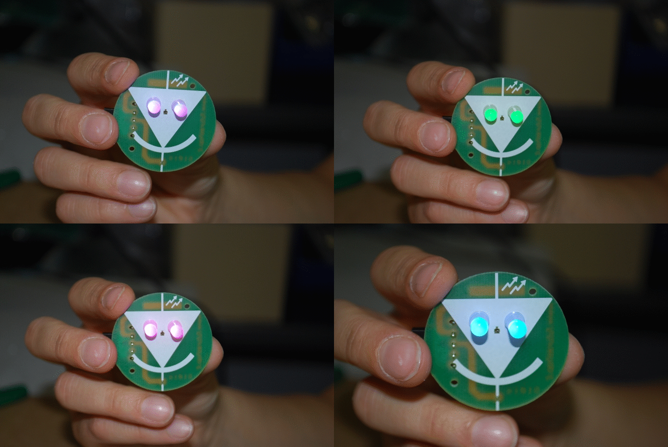
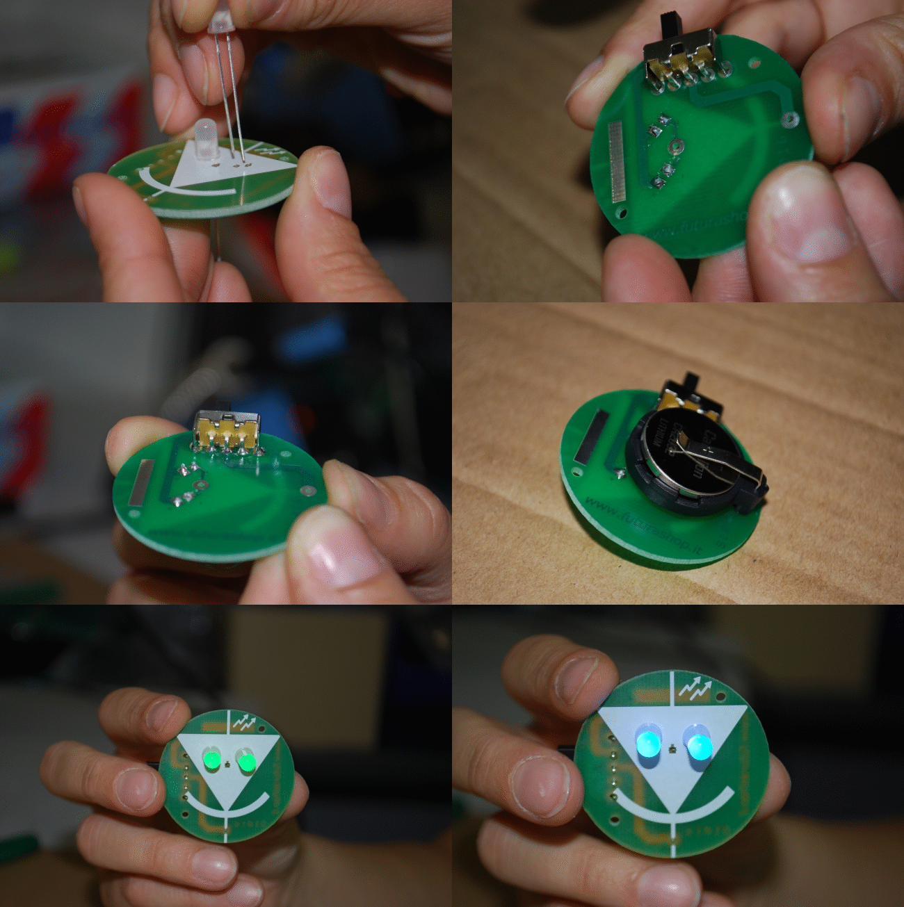
This small project is composed of a small pin hosting all the necessary components, namely, a battery, a switch, and two RGB LEDs. Once the switch is closed, LEDs turn on cyclically starting with red, and then lilac, violet, blue, green, yellow and restarting with red light again.
The question is that, how is it possible to change the color of the light without using any electronic circuits? Well, the answer is in the particular RGB LEDs used. They host a control circuit and three different colored LEDs, namely, red, green and blue. A LED (Light Emitting Diode) is a particular diode emitting visible light if polarized directly ( positive pole on the anode, negative pole on the cathode); all diodes, which are composed of a silicon and a germanium junction, if directly polarized, are able to emit light, however, the mentioned one always has a wavelength not visible by human eye.
Each of the RGB LEDs used in our project contains three junctions with a common terminal and each of them is turned on by a PWM generator. The control circuit modifies the duty cycle of the signals, offering the capability to obtain different light colors. The devices used for this project are similar to the commonly used LEDs and they just have two pins: the longer one is the positive pole and the shorter one is the negative one. They have to be powered with 3,2 V and, in this condition, they absorb 15÷20 mA. The maximum achievable luminosity (an average referred to all colors) in these conditions is about 1200 mcd. This type of LED is called RGB rainbow LED due to its ability to emit light in a various range of colors. In the market two versions of this type of LED can be found: one with a slower color transition and the other one with a faster color transition. In addition, it is possible to find them with opaque white or transparent (like glass) containers.
In our project, diodes are powered in parallel mode by a CR2032 cell battery. Between LEDs and the battery, there is just a switch allowing to turn on and off LEDs. There are no limitation resistors present because the voltage supplied from the battery is just enough to make LEDs turn on and it is very close to the suggested value in their datasheet. Limitation resistors, suggested for higher voltage like 5 V, will reduce the current flowing in the circuit and the color transition time consequently changes.


