
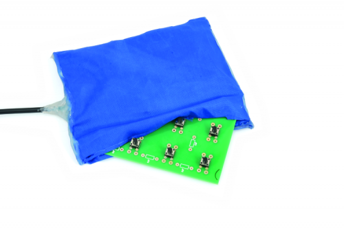
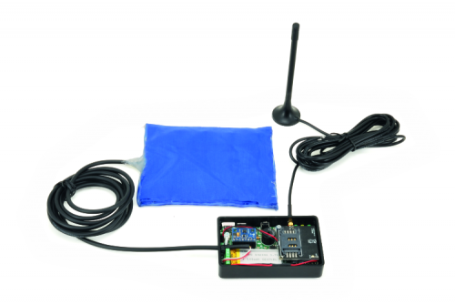
It is installed in cars, and thanks to a detector placed on the child seat, it warns us – via SMS or phone call – if we get away without bringing the child with us.
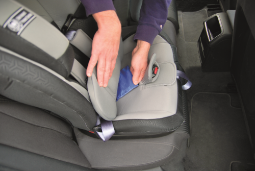
Among the most saddening (and at any rate, infrequent) accidents in the news, there are those of parents that – because of briskness, health problems or lack of attention – get out of the car and “forget” their kids on the child seat, in a hot or cold environment. Certainly, such accidents could have been avoided if someone or something reminded the driver that he left the child in the car; undoubtedly technology may help and offer solutions, to be implemented in the vehicle by the manufacturer or of the “retrofit” kind, such as the project here described here. That’s a device based on a GSM cell phone that detects some parameters, on the basis of which the behavior of the driver is evaluated and the necessary actions are executed: in particular, an SMS is sent to the phone of the driver that is getting away from the car. The device is installed in the car and is powered by the electric system of the latter; it verifies that the child is on its seat (by means of a sensor that is composed of some low-profile buttons, mounted on a breadboard to be placed under the cover of the child seat): if it turns out that the buttons are pressed (therefore, the child is sat), the circuit will also verify that the vehicle has stopped (by means of a triaxial accelerometer), if so and once the set time has elapsed, it will send an alarm SMS message to the driver’s phone and will let out a buzzer sound.
Moreover, it carries out a call to the same phone number and possibly to other ones, so that parents, friends, and other people may call the driver to verify what’s happening.
Even though the application of choice is the aforementioned one, the project has been created in our lab as a platform that may be adapted for the other two purposes. The first one is a residual-current device for elderly and fragile people, while the second one is a remote alarm, operating in the case of blackouts (and useful for the purpose of avoiding that the freezer defrosts and that the food therein contained becomes dangerous).
[bctt tweet=”Save My Child: the smart seat that sends text messages if you forget the child in the car” username=”OpenElectronics”]

Save my Child Circuit diagram
Let’s see therefore what is this all about, and analyse the electrical diagram of the circuit, whose management has been entrusted to a PIC18F46K20-I/PT microcontroller by Microchip, that has been programmed via our MF1361 firmware, so that it reads the status of the inputs (to which the child seat’s weight sensor, and a possible detection device, are connected), and acquires the signals supplied by the (U5) accelerometer, and talks to the (U4) external EEPROM (containing the settings for the system’s functioning) and interfaces a possible (U6) radio receiver, and manages a (GSM) cellular module.
Please notice that the circuit considers elements that may be mounted or not, since we conceived it as an expandable development platform, for those of you who wished to create their own application, starting from the base firmware.
Let’s start by describing the microcontroller, that – after the power-on-reset – initializes the lines RB1 and RB2 as inputs supplied with an internal pull-up resistor, that will be needed in order to read some normally open contacts that are connected to IN1 and IN2; the D2 and the D3 diodes protect the microcontroller in the case in which a voltage above the one of the PIC power source is erroneously applied at the inputs. IN1 is currently used for the child seat’s weight sensor, while IN2 is available for further possible controls: we may use it, for example, for the detection of the opening and closing of the doors, via the reading of the voltage on the courtesy lights; concerning this, please consider that in some modern cars the ceiling lights are managed (in PWM) by a junction box (in order to ensure a gradual switching on and off), while we just have to read the state of the lights instantly turned on and off (otherwise the reading will be an abnormal one); after that, we will have to filter the PWM by means of a capacitor placed between the microcontroller’s input and ground (after the diode). Another input is RB3, still supplied with an internal pull-up resistor, that is needed in order to read the P1 button (that is used in order to forcibly switch on the cellular module, that is normally switched off).
Still during the initialization of the I/Os, RB4 is set as an input for the purpose of reading – by means of the voltage divider R1 and R2 – the starting of the circuit, carried out by the double deviator SW1b; the voltage divider is needed since the microcontroller tolerates a voltage that is lower than the input one found on the power connector. The function of the RB4 has been reserved for future developments, it is explained considering that the circuit may be powered both by a network power supply via USB socket and by means of a lithium battery that is connected to the output of the dedicated charge regulator.
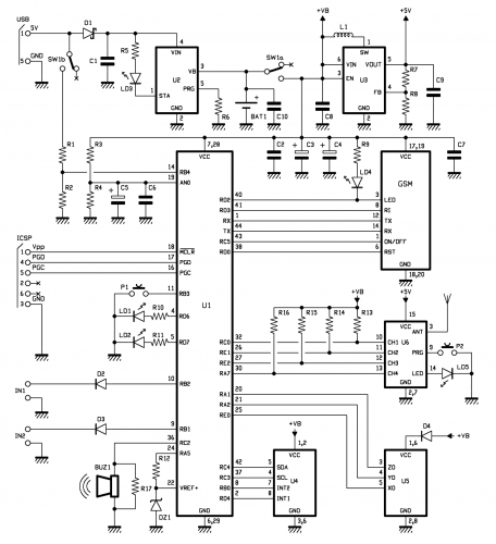
When SW1 is moved on the contacts that are marked with a cross in the circuit diagram, the rest of the circuit is isolated from the battery and therefore turned off; if at the input of the power source (USB) a 5 volt voltage is applied, only the charger stage will be operating (it is powered via the D1 diode, that protects it from polarity inversions). By moving SW1 to the switched on position, SW1b brings the input voltage to the RB4 line and SW1a powers the microcontroller and whatnot, by means of the voltage at the ends of the battery (about 4V when at full charge) in addition to turning on the step-up switching converter signed as U3, that generates the 5V needed by the rest of the circuit.
As regards the functioning of the circuit powered via USB, SWb brings the input voltage to the RB4, that – by implementing its reading in the firmware – allows to understand if the network power source is found; such a function is useful for the purpose of creating the anti-blackout alarm. On the other hand, during the battery operation, RB4 enables the microcontroller to know that and to carry out possible strategies to decrease the energy consumption (for example, by reducing the intervals in which the cell phone is turned on). The RB4 line is the only way the firmware has to understand when the circuit is battery operated, since if U1 is receiving power even if RB4 is at zero volts, it means that the circuit is battery operated, while if there is another power source, it will be functioning thanks to the voltage drawn from the USB.
Let’s return now to the I/Os initialization and see that the RC0, RE1, RE2 and RA7 lines are initialized as inputs, that they have been provided with an external pull-up resistor, given that we cannot activate it internally for such lines; they will be needed in order to read the channels of the hybrid receiver, that is anyway an accessory, reserved for future developments. Such a receiver could prove useful for the home usage as a remote alarm, for those that are impaired in their movement or forced on their bed; by detecting the variation at the outputs of the RX radio, it will carry out a phone call to ask for help or it will send a similar SMS. This is a possible application, but there are other ones; anyway, it must be implemented in the firmware.
RC3, RC4, RB0 and RD4 are the lines that have been assigned to the U4 accelerometer, that more specifically is a breakout board based on the MMA8452 triaxial accelerometer by NXP: RC3 is an output and it is needed in order to send a clock signal, RC4 is a bidirectional I/O and it drives the SDA, while the other two pins are inputs that have been reserved to the reading of the interrupts INT1 and INT2, that are generated by the accelerometer when certain events occur.
The RA1, RA2 and RA0 lines still are inputs, but they have been multiplexed on the A/D converter and are used in order to read the U5 triaxial accelerometer, that is also on the breakout board and that is based on the MMA7361 accelerometer module; such a component is intended as an alternative to the U4 (that is the one currently expected by our firmware) and supplies information concerning the accelerations detected on the X, Y, Z axes by means of analog voltages coming out from the corresponding lines. In this case, the firmware is simplified, since the MMA8452’s management routine is not needed (it requires the reading of registers, the implementation of the I²C-Bus protocol, and so on).
Still on the subject of ADCs, the An0 line is used in order to read the voltage level, that is supplied by the lithium battery, that powers the microcontroller and the rest of the circuit (save for the radio receiver); if the firmware considers it, it enables the possibility to shut down the whole when the battery is running low, or when it is under a certain voltage threshold. The RC2 line is initialized as an output and generates a series of digital pulses when the BUZ1 piezoelectric buzzer has to let out the warning acoustic note that has been indicated by the firmware; other two outputs are RD6 and RD7, that have been entrusted with the task to light the LD1 and LD2 LEDs.

Let’s complete the analysis of the I/Os with RD0, RD2, RD3, RC5, that along with the UART’s RXs and TXs from the interface towards the SIM800C cellular module by SIMCom; in the circuit the latter is mounted on a dedicated board to be inserted in the specific connector found on the printed circuit board. The module exchanges the data concerning the sent messages (the alarm ones) and the received ones (the configuration ones) with the microcontroller, via the PIC’s UART, that is also needed for the commands for the settings of the cell phone; the rest of the lines concerns some state signals: RD2 reads the output for the “signal” LED that is repeated by LD4, while RD3 reads the Ring Indicator, that is to say, the cell phone contact that supplies the high logic level when a phone call is received. The RD0 line enables to reset the module and RC5 deals with the switching on and off; reset and ON/OFF are implemented by the circuitry on the board on which the SIM800C is mounted upon.
The board, whose circuit diagram has been shown – along with the pinout of the insertion connector – in Fig. 1, contains the SIM800C cell phone, an MMX 90° antenna connector and a 2mm male 2×10 pin-strip on which the power source, the ignition control line (PWR), all the signals and the serial communication lines from and towards the GSM module, as shown in Fig. 1.
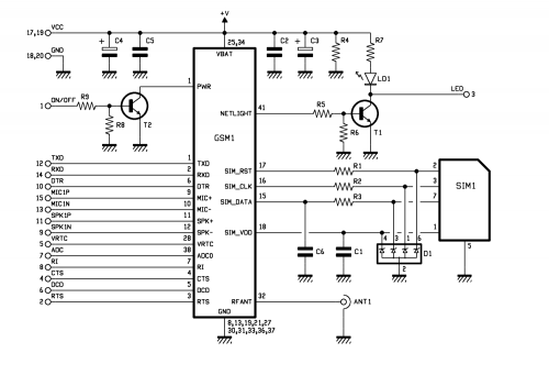
Fig. 1
Since the microcontroller’s I/Os have been defined, we may take a look at the two sections involved in powering the circuit: the charger and the DC/DC step-up converter.
The charger is based on the MCP73831T integrated circuit (U2), manufactured by Microchip; as an input it typically accepts 5V (the tolerable range is between 3.75V and 6V), coming in this circuit from the USB connector; it supplies – at the output – the current needed in order to charge lithium ion or lithium polymer (Li-Po) elements, and supplying up to 550mA. A battery (to be connected to the +/- BAT contacts) may have a theoretically unlimited capacity, since at most it would be charged in a very long time, however please consider that by means of a 550mA current, a 550 mAh element is charged in an hour; since we chose a 500 mAh cell, it will be charged in less than an hour.
The integrated circuit operates in the typical configuration, in which the LD3 light diode is driven by the STAT output, that is brought to the low logic level when charging, while it remains at a high logic level when it stops charging; the same is brought to a high impedance (open) when the MCP73831T is shut down or when it turns out that no battery is connected to the VB output. VB (pin 3) is the output that is used for the lithium battery. The integrated circuit carries out the charging with constant current and voltage. The charging current (Ireg) is set by means of a resistor connected to the pin 5 (in our case, that’s R6); its value is connected to the resistance by the following relationship:
Ireg = 1,000/R
in which the R value is expressed in ohm if the Ireg current is expressed in A. For example, with 4.7 kohm a 212 mA limitation is obtained, while with R being 2.2 kohm the current is worth about 454 mA. if the pin 5 is opened, the integrated circuit is brought to the idle state and it only absorbs 2 µA (shutdown); the pin may, therefore, be used as enabling.
Let’s complete the description of the circuit diagram with the step-up converter, that draws 5 stabilized volts from the battery voltage; the stage is based on the MCP1640BT-I/CHY integrated circuit, that’s a synchronous boost regulator. There’s a PWM generator inside it, that drives a transistor whose collector periodically closes the L1 coil to ground, by means of the SW pin, it charges it and lets it release the accumulated energy during the pauses – by means of the pin 5 – to the C2, C3, C4, C7 and C9 filter capacitors. The diode clamp protecting the internal transistor is also an internal one, thus reducing the external components needed to the bare minimum: in fact, there are the filter capacitors between Vout and ground, the L1 inductor and the resistive divider between Vout and FB that deals with the reactivation of the PWM generator via the internal error amplifier, by stabilizing the output voltage at the desired value. By modifying the ratio between R7 and R8 it is, therefore, possible to modify the voltage supplied by the Vout pin, but that’s not in our interest to do that.
Settings and commands for Save my Child
Once the installation has been completed, you will have to configure the unit; such an operation is carried out via SMS, therefore please insert an operational SIM in the SIM holder of the 7100-FT1308M module, and take note of the corresponding telephone number. After that, please give all the required commands via a cell phone: they are all shown in Table 1.
Among the first things to do there is the configuration of the telephone numbers in the list of those that the system will call or to which the alarm SMS messages will be sent, in the case of a kid on the child seat that has possibly been “forgotten abandoned”. In order to facilitate the procedure, given that the system is protected by the password as for this operation, an Easy Setup mode has been designed: during the first time it is started, the system will save the first telephone number that calls it, and considers it as the first number in the list. This number will be able to carry out modifications, even without passwords; anyway the commands may be sent by any phone, as long as the corresponding SMS includes the password, and even though – in order to speed up some commands – we allowed that those sent by the telephone numbers in the list may be given without need for passwords. As for the commands concerning the addition and the deletion of telephone numbers from the list, the request of a password makes it so that the list is managed only by a person that is enabled to do it.
Let’s move on now to the description of the commands and to the corresponding syntax, with the premise that the circuit also accepts SMS messages containing more than a command; in that case the commands must be separated from the following one, by means of a comma.
The first command examined is the one that modifies the password, it consists in an SMS such as PWDxxxxx;pwd, in which the new password (composed of five numbers) must be written in the place of xxxxx, while pwd indicates the current password. The default password is 12345.
Table
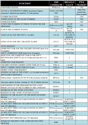
The memorization of one of the eight numbers enabled to send configuration commands is carried out by sending an SMS, whose text contains the NUMx+nnnnnnnnnnnnn;pwd text, in which the position (which number is being memorised) must be written in the place of the x, the telephone number goes in the place of the ns, while pwd is the current password. All of it must be written without spaces.
Numbers that are 19 figures long are permitted, while the + substitutes 00 as the international call prefix, on the cell phones. For example, in order to add the 00398911512 telephone number in the third position, you will have to send a command like this: NUM3+398911512;pwd. The password is only needed when you try to save a telephone number in a position that has already been occupied by another one; on the other hand, if you have to add a number in an empty position, you will just need to send an SMS with the following text: NUMx+nnnnnnnnnnnnn.
The deletion of a number is executed via an SMS containing the NUMx;pwd text; in the place of the x you will have to write the position of the telephone number to be deleted, while pwd is the usual password. For example, in order to delete the fourth telephone number from the memorized list, a message containing the NUM4;pwd text is needed. In order to request the list of the telephone number memorized in the circuit, you will have to send an SMS containing the following text: NUM?;pwd. The board answers to the telephone number from which the interrogation is coming.
It is possible to know the quality of the GSM signal by sending the QUAL? command; the system will reply with an SMS containing the current situation. The message will be sent to the telephone that sent the command.
Let’s move on now to the input state and configuration messages: LIV? allows to know the state of the inputs; IN2 may operate both at a voltage level (it is set via LIV2:b, that triggers the alarm when the input is open) and at a variation one (it is set via LIV:v). As regards the inputs, it is possible to set an inhibition time, via the INI1:mm command (the interdiction minutes go in the place of mm) for IN1 and via INI2:mm for IN2; the inhibition is needed in order to avoid sending continuous warnings if the input – in the level mode – remains open. In order to define which numbers in the list have to receive phone calls, you have to sent the VOCxxxxxxxx:ON;pwd message, with the same rules used for the management of the telephone numbers to which to send the SMS messages.
The reply message is a very similar one: “Number memorized: Posx V+nnnnnnnnnnnn, Posy V+nnnnnnnnnnn.” The S of SMS has been replaced by the V of voice. Even in this case, there are two different commands for the deactivation: SMSxxxxxxxx:OFF;pwd deactivates the sending of messages and VOCxxxxxxxx:OFF;pwd disables the possibility to make phone calls. The xs represent the positions of the numbers that must not receive the alarm warnings.
We need to clarify something concerning the command for the setting of the telephone numbers to call or to which to send the alarm SMS messages: as per default settings of the firmware and after each total reset, the system will direct both the calls and the SMS messages, to all the memorized numbers. Consequently, in order to leave out some of them, it is needed to send the deactivation commands: SMSxxxxxxxx:OFF;pwd or VOCxxxxxxxx:OFF;pwd, and to indicate the positions to leave out.
The system sends an SMS to the telephone number occupying the first place in the list, each time it is newly powered. Such a function may be disabled/enabled via the AVV0 (deactivate) and AVV1 (activate) commands; the default text is SYSTEM STARTUP.
Let’s move on now to the commands that enable the memorisation or the overwriting of the SMS messages to be sent: the syntax is like that of TINn:xxxxxxxxx, in which n is the number of the input the message is referring to, while the xs correspond to the text message, that must not exceed a length of 100 characters.
An essential setting is the one concerning the IN1 observation time, that is carried out via the OSS1:ss command, in which the time (ranging between 0 and 59 seconds) goes in the place of ss: it indicates to the circuit for how much time the buttons must remain pressed from the time it has been detected that the car has stopped and before the alarm generation. The delay is of the essential, in order to avoid that a false alarm arises when you stop for a short time. Under this point of view the firmware, when the circuit is powered (when the dashboard is turned on), waits for a time that is twice the set one, in order to allow the driver to carry out operations such as closing the garage door or fastening the safety belts, etc.
An observation time for IN2 may also be defined, with the same procedures, by giving the OSS2:ss command; it is also possible to request the currently set times via SMS (OSS? command).
Let’s complete this overview on the commands with the one that returns the default settings: that’s RES;pwd. The reply message is “Reset”.
The rest of the commands has been described in Table 1.
Conclusions
The project we proposed here is an open platform; it is possible to use it in order to create many applications, among which there are: the alarm to prevent forgetting children in the car, the remote care system and the remote alarm we mentioned before. More in general, that’s a system that is capable of generating warnings and notifications via phone, when certain events – that are not necessarily emergencies – occur, and therefore they also serve for purposes of remote monitoring.
Components List:
C1, C8, C10: 1 µF ceramic capacitor (0805)
C2, C6, C7, C9: 100 nF ceramic capacitor (0805)
C3, C4: 470 µF 6.3 VL tantalum capacitor (D)
C5: 4,7 µF 6.3 VL tantalum capacitor (A)
R1, R2, R4: 10 kohm (0805)
R3, R12: 1 kohm (0805)
R5: 470 ohm (0805)
R6: 3.3 kohm (0805)
R7: 470 kohm (0805) 1%
R8: 150 kohm (0805) 1%
R9÷R11: 470 ohm (0805)
R13÷R16: 10 kohm (0805)
R17: –
U1: PIC18F46K20-I/PT (MF1361)
U2: MCP73831T
U3: MCP1640BT-I/CHY
U4: Breakout board cod. 2846-MMA8452
U5: Breakout board cod. 7300-MMA7361 (unused)
P1: 90° Microswitch
P2: –
LD1: 3 mm yellow LED
LD2, LD4: 3 mm green LEDs
LD5: –
LD3: 3 mm red LED
D1÷D3: MBRA140T3G
D4: MMSD4148
DZ1: 2.7V 500mW Zener diode
L1: 4.7 µH 770mA wire-wound inductor
BUZ1: Buzzer without electronics
Other information:
– 8-way female strip-splitter
– 9-way female strip-splitter
– 6-way male strip-splitter
– 2mm pitch 2×10 female connector
– 2.54 pitch 2-way terminal (3 pcs.)
– 2 mm pitch 2-way JST Connector for PCBs
– 500mA LiPo battery with 2 mm JST connector
– S1361 (85×51 mm) printed circuit board
From openstore
Child Life-Saving Car Seat Alarm

[…] Save My Child: The smart sensor that sends text messages if you forget the child in the car – [Link] […]
[…] Save My Child: el sensor inteligente que envía mensajes de texto si olvidas al niño en el auto – [Link] […]