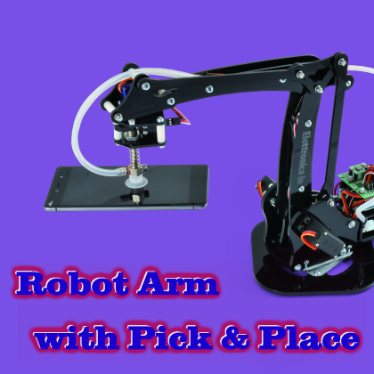
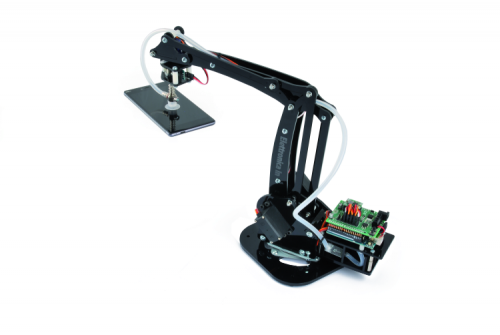
We equip the robotic arm published in the previous issue of a pneumatic system for gripping and releasing objects, controlled through an Arduino shield created for the purpose.
You will have had the opportunity to appreciate the qualities and potential of the robotic arm with manipulation terminal clamp presented in the previous article, to test which we used an Arduino board combined with an Octopus shield. For those who missed the article, briefly remember that it is a robotic arm in plexiglass with a steel ring, with four degrees of freedom (so-called anthropomorphic, because it moves almost like a human); the arm is of articulated type, since all the joints are rotating, (rotation of the base, movement of the shoulder, of the elbow and rotation of the wrist) which, together with the pincer at the extremity, give a certain ability to position and orientate small objects. The robotic arm was designed not only to take its first steps by experimenting and developing robotic applications, but it can also be applied in the execution of repetitive movements of small objects and packing in the production sector.
In the introductory article, we explained how to command the servo through Arduino UNO REV3 (or Fishino UNO) equipped with the Octopus shield, specific for the servo control. In the application described in these pages, instead, we will propose a dedicated electronic control, based on an ad-hoc shield set up to control the servo commands driven by Arduino, through the PWM outputs, but also to acquire the analogue signal of the potentiometer where we decide to use servomotors with position feedback that “carry” the signal of the coaxial potentiometer to the outside.
This function is very useful, for example, for precision positioning, since it allows you to correct any errors or tolerances due to the play of joints, but also to learn the movements to build sequences to be performed at a later time and automatically; the learning can be carried out by moving the arm manually to the desired positions, then recording them and then inserting them into a firmware that repeats the relative movements, aiming at reaching the angles of rotation of the servos involved in the movements themselves.
However, consider that the system works safely even with traditional servos, such as those included in the basic robotic arm.
Among the various functions implemented, the shield takes care of supplying the servo power supply and of controlling the solenoid valve electromagnet and the vacuum pump that allow the pick and place.
Pick up and release the object
That said, we can get into the heart of the application, which consists in equipping the robotic arm of a system for picking up and releasing small objects based on a suction cup connected to an aspirator (a small vacuum pump) by means of a three-way electric valve, which allows switching the suction cup on the pump or on a vent; the latter allows the immediate release of the picked up object. To limit the consumption of electricity by the solenoid valve we have chosen to use the common joint normally connected for the suction cup and connect the same to the vacuum pump.
The manipulator of the objects, i.e. the suction cup, must be mounted instead of the clamp, which will then be removed; the base will remain, i.e. the wrist, operated by the usual 1.2 kg/cm servo control which will allow the rotation to rotate, if necessary, with the picked-up piece. The suction cup is perforated inside and communicates with a small tube, which goes into the common solenoid valve connection, the two of which terminate, one on the vacuum pump and the other on a vent, which allows the suction cup to be brought to atmospheric pressure when the valve switches from the pump to the vent itself. The suction cup is supported by a stem attached to the top of the support bracket (which allows attachment to the wrist of the arm) by means of a nut that grips its threaded end; between the support bracket and the pneumatic connection of the suction cup a spring is interposed that allows the soft grip because if the arm to falls down, the suction cup and its stem can fall to a certain extent.
The operation of the pick & place system is as follows:
- The suction cup is positioned on the object to be picked up and pushed onto the surface of the latter until it adheres;
- With the shield, the Arduino operates the vacuum pump and, as the solenoid valve at rest connects directly the suction cup, the latter sucks the piece keeping it attached to it;
- Arduino commands the arm to remove the piece and position it in its destination;
- At this point the Arduino activates the solenoid valve, which switches the common connection on the vent when the depression stops and the object can fall;
- Once the object is released, the electronics will return the arm to its original position and prepare for a new pick up.
These steps summarize the activity of the arm, to perform which you need an electronic control commanded manually (for example through two joysticks) or automatically through a special firmware in which to memorize the movements to be performed and their speed, which should not be excessive in order to prevent the joints of the arm are stressed so much to gamble in the long run. In this article we will provide you with a basic arm management tool, which consists of a sketch for Arduino capable of executing the sequential movement of all the actions of the arm and also of the solenoid valve; in it it will be enough to replace the predefined parameters with those desired to make the robotic arm perform the actions we want. We will explain how when we describe the application firmware.
The electronic control
The control of the four servo controls of the robotic arm is entrusted to Arduino UNO, through the shield of which you find the wiring diagram in these pages; from it you see how it is something simple, summarized in the extension of the analogue lines (1 PWM and an analogue input for each of the servos) of Arduino on the servo control connectors, which this time have four pins instead of three, since we added that, optionally, for spindle rotation feedback.

This is possible because the Arduino/Fishino UNO board has six PWM outputs and allows direct control of the same servo controls, at least for the position signals; the electromagnet of the three-way valve is instead managed through a digital I/O line, wherein the pilot shield a transistor is used as a static switch. The shield is not limited to supply the servo control signals, but it also supplies the 5V power supply with all the current that the 13 kg/cm servo controls require to operate, even from the cues coinciding with the start of the servo controls, especially when the arm is under load.
Without using the shield, we would have to wire the mass and + 5V of the servo, then connect the + and – poles to an external power supply, while with the shield we obtain a compact set, since all the electronics necessary for the system’s operation are included between Arduino UNO and the shield.
So let’s take a look at the electric diagram of the shield, in which, to make it easier to understand, we placed Arduino ONE in the center: as you can see, the left connectors are those for the servos and on them the 5V power supply is repeated from the output of the voltage regulator, which you see signed U1; S1 is reserved for servo control 1, S2 at 2 etc.
For the assignment of the servos, we refer to Table 1, which shows the correspondence between them and the part of the arm which they move.
This assignment reflects that made in the firmware and the two connections S5 and S6 have been implemented for future developments, i.e. to add functions to the arm or manage services related to its activity.
Table1

As mentioned, each connection has four poles because, in addition to the two power supplies (5V) and the PWM output for the control, we have provided a position for feedback input provided by the servos. So for each servo, Arduino reserves a PWM output and an analogue input; for example, taking S1, the servo output is D11 and the feedback input is A0. The connectors for the servos are each made up of a 4-pole pin strip, whose pin-out reflects the standard adopted by the servos with feedback.
On the output side, Arduino UNO controls two static switches formed by a cascade of BJT transistors and N-channel MOSFETs, to operate the vacuum pump and the three-way solenoid valve, as well as, directly, an LED (LD3, powered through the resistance R9 with the output D13); through D12, on the other hand, interfacing with a digital output sensor is provided through the SENS connector: this is a sensor on the terminal part of the arm, which in this application is not used, to detect when, by lowering the suction cup, this presses more than it should. In practice, the sensor is a microswitch that detects the withdrawal of the suction aspirator, which is constrained to the head of the arm by means of a spring system that allows it to move back up to a certain point, to ensure a soft contact with the piece to be manipulated.
By appropriately rewriting the firmware, the sensor can be another of your choice, digital, which uses only one wire for communication (for example a 1-wire device).
Let us dwell for a moment on the OUT1 and OUT2 outputs, which are identical and therefore, describe only one of them, without prejudice to the fact that what has been explained for one is also valid for the other; we take into consideration OUT1, whose control is entrusted to the D2 line of Arduino, which, at a high value level (5V) through the resistive divider R1 / R2, polarizes the base of T1, sending the latter into saturation, a condition in which the voltage Vce almost vanishes, sending the low level gate of the MOSFET Q1. Since it is the N-channel enhancement mode, it remains blocked and the OUT1 output does not supply any current. On the other hand, when Arduino sets to value zero D2, the transistor T1 remains in interdiction and the gate of Q1 is supplied through R3, a condition which determines the entry of the MOSFET in ON state: the current which can now flow between the drain of Q1 and ground illuminates the status LED LD1 and supplies any connected load between + and – of OUT1, which supply a voltage of about 5V (the voltage drop between drain and source of the MOSFET is negligible, at least to the currents in play ).
We now move on to the power supply stage, which is based on a breakout board (U1) based on the integrated WP1584: it is a compact buck type DC / DC voltage regulator, starting from an input voltage of 12-15V obtains well-stabilized 5Vcc, providing a current of 3A. The regulator has two input contacts (IN + and IN-) connected respectively to the cathode of the protection diode D1 (used to block the current in case the shield is powered with the polarity inverted by mistake) and to ground, and two output, which provide the stabilized voltage. The shield does not then take power from the Arduino (in fact none of the power supply pins of the latter board is connected) but from a separate DC jack on board, which in the electric diagram is labelled PWR; the input power passed through the protection diode is filtered by the capacitors C1 and C2 and the stabilized one, at 5 volts, by the capacitors C3 and C4.
We conclude the analysis of the electric diagram with the Arduino I / O D7 and D8 lines, which are inputs that acquire the status of the P1 and P2 buttons, intended for future applications, that is to start and stop the learning of movements, for example.
The pneumatic manipulator
This is the electrical and electronic part, however, in order for the robotic arm to handle the objects, the pneumatic suction cup manipulator must be applied to the wrist, which is done by assembling two 3 mm plexiglass plates as shown in Fig. 1 (where you see the body with the limit switch microswitch board applied, but without the suction cup and its spring support) by means of 19 mm plastic tubular spacers. The cross-shaped bracket supplied with the mini-servo must be fixed to the plexiglass top plate using 4 cross-head 2×6 TB self-tapping screws. When closing the two plates, insert the microswitch support, to which the circuit must be fixed, containing the microswitch that detects the compression of the suction cup system. When closing the body delimited by the two plates remember that the fork of the plexiglass guide for the suction system must be oriented towards the tongue of the microswitch and centred with respect to the hole of the bottom plate. Now place the wrist at the end of the forearm by matching the holes on both sides and fasten it to the forearm using an M3x35 TB cross screw, 4 flat 3×6 washers, a 3×15 ABS spacer and a self-locking M3 nut.

Fig. 1
Apply the servo bracket spacer (in 3 mm plexiglass) on the mini-servo crosspiece mounted on the suction cup head, positioned halfway the pin of the mini-servo of the wrist, then insert on it the double lever fixed on the suction cup head so that the latter is aligned with the wrist.
Fix the suction cup head to the servo pin with the 2×4 self-tapping screw supplied to the servo, then apply the suction cup that best suits your needs to the lower end of the suction cup. Apply one end of the silicone tube supplied with the kit to the solenoid valve terminal C.
Stretch and fix the tube along the arm so that the free end can reach the suction cup head without impeding movement. To complete the work, push the end of the tube onto the suction cup coupling (holding it with one hand to avoid pushing the suction cup head). The silicone tube can be shortened if necessary, but first, it is necessary to check that it is able to reach the suction cup head even in the most extreme conditions (maximum and minimum extension of the arm, etc.) without undergoing bottlenecks which would reduce the suction power. Now the assembly of the mechanical parts of the arm is finished. All that remains is to stretch and possibly extend (with M / F cables) the electric cables of each servo so as to make it reach the control board without interfering with the moving parts.
The limit switch sensor must be connected to a 60 cm M / F extension cable.

The firmware
Now it’s time to approach the firmware aspects describing the sketch we have prepared ad-hoc to make the robot arm work and explaining how to set the parameters in order to make the arm perform the desired movements.
The firmware includes a series of sections that describe the movement, understood as the rotation of the servo and the time it takes to get it, one for each of the servos that the shield can handle, then 6.

To realize a sequence, it is enough to customize these parameters and remember that you must make the movements to the desired angle for each servo, record the angle, then connect Arduino to PC, edit sketch parameters, then reload the sketch and run in a loop. The sketch is shown in Listing 1 and basically performs the positioning sequence of the pneumatic head, passing from the starting position A, moving to the B (where the piece is located), letting the head go down, operating the vacuum pump (the solenoid valve it is at rest, thanks to the digitalWrite (valve, HIGH) instruction and then raising the head and moving back to position A, in which it releases the piece through the interruption of the depression, operated by feeding the solenoid valve digitalWrite (valve, LOW) and bringing the pump to OFF. All this is obtained by using the arm.h and servo.h libraries which manage the movements in their entirety.
Each ServoMovement instruction determines the displacement of servo controls that must be written in brackets, separated by commas and preceded by the time taken to complete them. For example (40, 120, 110, 90 etc.) indicates that the positions in degrees must be reached in a time equal to 40.
listing1
#include <Braccio.h>
#include <Servo.h>
#define pump 2
#define valve 4
Servo base;
Servo shoulder;
Servo elbow;
Servo wrist_rot;
Servo wrist_ver;
Servo gripper;
// the setup function runs once when you press reset
// or power the board
void setup() {
// initialize digital pin LED_BUILTIN as an output.
pinMode(pump, OUTPUT);
pinMode(valve, OUTPUT);
digitalWrite(pump, HIGH);
digitalWrite(valve, HIGH); //HIGH ASPIRA LOW RILASCIA
//For each step motor this set up the initial degree
Braccio.begin();
}
void loop() {
//go in position A
Braccio.ServoMovement(40, 120, 110, 90, 100, 90, 90);
Braccio.ServoMovement(40, 120, 60, 90, 100, 90, 90);
delay(500);
Braccio.ServoMovement(40, 120, 60, 90, 100, 90, 90);
Braccio.ServoMovement(40, 120, 60, 100, 100, 90, 90);
//I go down and say no.
Braccio.ServoMovement(10, 120, 60, 100, 50, 90, 90);
//no no
Braccio.ServoMovement(10, 120, 60, 100, 150, 90, 90);
Braccio.ServoMovement(10, 120, 60, 100, 50, 90, 90);
Braccio.ServoMovement(10, 120, 60, 100, 90, 90, 90);
delay(1000);
// I go to position B and I get down.
Braccio.ServoMovement(40, 120, 110, 90, 100, 90, 90);
Braccio.ServoMovement(40, 70, 60, 90, 90, 90, 90);
Braccio.ServoMovement(40, 70, 60, 110, 90, 90, 90);
//I'll start the pump.
digitalWrite(valve, HIGH);
digitalWrite(pump, LOW);
delay(1000);
//I get up
Braccio.ServoMovement(40, 70, 60, 90, 90, 90, 90);
Braccio.ServoMovement(40, 70, 110, 90, 90, 90, 90);
Braccio.ServoMovement(40, 70, 110, 90, 50, 90, 90);
//I'm going to position A
delay(1000);
Braccio.ServoMovement(40, 120, 110, 90, 100, 90, 90);
Braccio.ServoMovement(40, 120, 60, 90, 100, 90, 90);
delay(500);
// I'm down
Braccio.ServoMovement(40, 120, 60, 110, 100, 90, 90);
//I turn off the pump.
digitalWrite(valve, LOW);
digitalWrite(pump, HIGH);
delay(1000);
//mi alzo
Braccio.ServoMovement(40, 120, 90, 90, 100, 90, 90);
Braccio.ServoMovement(40, 120, 90, 90, 90, 90, 90);
//I'm going to position B
delay(1000);
Braccio.ServoMovement(40, 70, 60, 80, 90, 90, 90);
Braccio.ServoMovement(40, 70, 60, 100, 90, 90, 90);
//Mi abbasso
delay(1000);
//e dico no no
Braccio.ServoMovement(10, 70, 60, 100, 50, 90, 90); //no no
Braccio.ServoMovement(10, 70, 60, 100, 150, 90, 90);
Braccio.ServoMovement(10, 70, 60, 100, 50, 90, 90);
Braccio.ServoMovement(10, 70, 60, 100, 90, 90, 90);
//Wait 1 second
delay(1000);
//I get up and go to position A.
Braccio.ServoMovement(40, 120, 110, 90, 100, 90, 90);
Braccio.ServoMovement(40, 120, 60, 90, 100, 90, 90);
delay(500);
//I'm down
Braccio.ServoMovement(40, 120, 60, 90, 100, 90, 90);
Braccio.ServoMovement(40, 120, 60, 110, 100, 90, 90);
//and I'll start the pump.
digitalWrite(valve, HIGH);
digitalWrite(pump, LOW);
delay(1000);
//i get up
Braccio.ServoMovement(40, 120, 90, 90, 100, 90, 90);
Braccio.ServoMovement(40, 120, 90, 90, 90, 90, 90);
//Wait 1 second
delay(1000);
//I'm going to position B
Braccio.ServoMovement(40, 70, 60, 90, 90, 90, 90);
Braccio.ServoMovement(40, 70, 60, 110, 90, 90, 90);
digitalWrite(valve, LOW);
digitalWrite(pump, HIGH);
//dico no no
delay(1000);
Braccio.ServoMovement(40, 70, 60, 90, 90, 90, 90);
Braccio.ServoMovement(40, 70, 110, 90, 90, 90, 90);
Braccio.ServoMovement(40, 70, 110, 90, 50, 90, 90);
//Wait 1 second
}
Conclusions
The project described here is a scalar application, born as a demo of the manipulation possibilities offered by our robotic arm, but extensible to any application and to any type of robotic arm similar in degrees of freedom and implementation.
It is only a matter of putting the firmware to hand and starting from this base it is possible to create complex applications, which come out of the education world, moving to the professional.
From openstore
4″ Aluminium rotating bearing turntable
SUB MICRO SERVO 9g – 22x11x29 mm
SERVO 55 g – 13 kg/cm – METAL GEAR
Octopus – Shield 16 I/O for Fishino and Arduino -kit
Pick & Place for Robotic Arm “ROBOARM”
