Home cinema becomes even more immersive thanks to Raspberry and addressable LEDs: let’s re-create the Ambilight TV effect on any other TV using Raspberry and Kodi.
What’s better than watching a movie in front of your TV in the summer heat or …under a warm blanket in the winter? Once the perfect mood is set, why not enjoy your experience in the best possible way, but the help of technology? Yes, the project described in this article was born with the goal of giving a boost to any modern flat screen TV, from the first models to the latest smart TVs but all their interesting features.
In the early 2000’s, Philips R&D labs designed a system they called “Ambilight” which, using RGB LEDs applied on the edges of the TV, allowed to project colors matching the video content visualized in any given moment on the wall behind the TV.
This technology allowed to bridge the brightness gap between the image on the TV and the wall around it, thus eliminating some known glare and helping the viewer visualizing more details in the image; at the beginning, there was a separate track to manage the film’s color information on the LEDs, but this way, every movie studio would have had to add those tracks to every movie during production phase: the second version of Ambilight would pick up color information directly from the video on screen, in real time.
The screen’s edges are divided into logic sectors, and each sector is associated with a specific LED and, by making a color average of the pixels, you can find the color to set to be reproduced by the LEDs; this operation is repeated for all the LEDs mounted on the TV and all of this is repeated hundreds of time per second in order to provide synchronicity and maximum smoothness to the colors projected around the TV.
With RaspiLight we can re-create this technology and apply it to any flat-screen TV, but there’s more: even when the TV is off, we can control the system through an Android or iOS app and create static or dynamic light effects and make the TV an animated lighting point and not just a simple lighting piece of furniture.
In order to create our project, we need the following components, which you can find on our store:
- Raspberry Pi 3: with Kodi installed it will become a media center, where a program will run in the background taking care of analyzing the edge of the video transmitted and send the information regarding LED colors to Arduino;
- Micro SD: 16 GB recommended;
- Raspberry Pi power supply: 5V 3A recommended;
- A 470 ohm resistor;
- RandA: RandA will be installed directly above Raspberry Pi as a shield;
- A strip of addressable RGB LEDs: 5-m 300-LED strip with control chip WS2812B;
- LED strip power supply: 5V with proportionate current based on length of the LED strip’s Mike on this value must be calculated by adding up the length of four edges of the TV.
As for power supply, consider that, roughly, an RGB LED strip of 5m needs typically a maximum of 8.5 A.
We chose to develop this project using Raspberry Pi 3 because, besides being the most powerful device of the series, it also offers built-in wireless connectivity that translates in an objective advantage when we are going to place it under our TV; in fact, we won’t need to connect an Ethernet cable or an additional Wi-Fi USB dongle.
Moreover, since it also has Bluetooth connectivity, we’ll be able to control our media center in several ways, through Bluetooth keypads and remote controls, with an app from smartphone or tablet over Wi-Fi, or directly through remote control of our TV if it has CEC functionality.
This feature, which is nowadays included in almost any new TV, allows to use the provided remote to control all the devices connected to the TV through HDMI cable (decoder, multimedia players and Kodi media center on Raspberry Pi).
The unique feature of addressable LED strips, which have considerably grown in popularity over the last years, is that we can control brightness and color of each single LED through an associated chip; with this feature, we can create any kind of animation using a microcontroller, an Arduino or a Raspberry Pi.
Applications are many: dynamic lighting, timed effects and, if we place strips one over the other to create a LED matrix, with can also create a PC-controlled, LED maxi screen.
The strips are available with 30, 48, 60 and 144 LEDs per meter, we chose the strips with 60 LEDs per meter to have a good correspondence between the video on TV and the colors projected on the screen; this because by choosing a strip with a bigger distance between each LEDs, we would have had color “gaps” and the end result wouldn’t have been optimal, while on the other hand, with 444 LEDs per meter, LED density for each single sector would have been uselessly bigger, increasing power consumption of the whole system and creating lighting hues we wouldn’t even be able to perceive.
SOFTWARE
The pieces of software we are going to employ are basically four: Kodi (which we have already talked about in issue #201 in the article on the Raspberry Pi Media Center), HyperCon, Hyperion and a sketch for Arduino.
Kodi
This is a program we are going to install on Raspberry Pi in order to turn it into an actual media center, capable of playing full HD video content, photos and music; everything is connected to our home network so that sharing multimedia content to display them on TV is quick and easy.
HyperCon
This program will run on our PC, we’re going to indicate the number of LEDs on the sides of our TV and other parameters that we will analyze in-depth later; these will be used in order to create the config file that will be uploaded on Raspberry Pi.
Hyperion
This program will be installed on Raspberry Pi and will run in the background every time Kodi is launched; its task is to analyze the sectors on the edges of the screen and send out LED colors for all the strip through a serial connection to Arduino or RandA.
Sketch
We will upload a simple sketch on RandA (our Arduino board interfacing with Raspberry Pi) that will take care of receiving information from Raspberry Pi and assign colors to the LED strip attached to it; before uploading this sketch we will modify a few parameters to adapt it to our system.
Besides these four programs, we are going to use another configuration software, Boblight Configurator, that will allow us to calculate the prefix of our LED strip: “prefix” is a series of hexadecimal numbers that depend on the number of LEDs we have for each side of our TV; we are going to insert this parameter in the sketch before uploading it on RandA. These way, the strip will be recognized and Hyperion and Arduino will be synchronous during serial communication.
There are several software’s just to analyze the various video sectors during reproduction and assign colors to the LED strips lining the screen, the most famous are Boblight and Hyperion; we went with Hyperion because it has some advantages: the code is much more optimized, since the lag (LAtency Gap) between video and LED coloring is zero (Boblight has almost 1 second delay, in many cases). Besides, the whole system is much more comfortable, allowing us to fine-tune it and calibrate LEDs’ colors, control LEDs from the PC and app for smartphone and execution of lighting animations even when the TV is off.
Then, we are going to use the Boblight system configurator only to calculate the “prefix” parameter to write in the sketch, because Hyperion configurator does not offer this feature.
REALIZATION
Now, let’s take a look at the practical side of the project, which involves preparation of hardware, wiring, installation and configuration of the corresponding software.
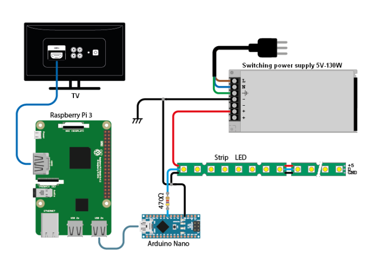
Let’s start from assembling the electric and electronic part, for which you have to follow the diagram in figure , keep in mind that in this application we are using Raspberry Pi as the brain and our RandA (Raspberry and Arduino) board to interface with the LED strips. For those of you who are still not familiar with it, RandA is the hardware we have designed and developed, which is inserted in the Raspberry Pi and gives us the possibility to use Arduino hardware and the white range of ready-made libraries offered by the Arduino world for controlling standard devices (e.g. LED strips).
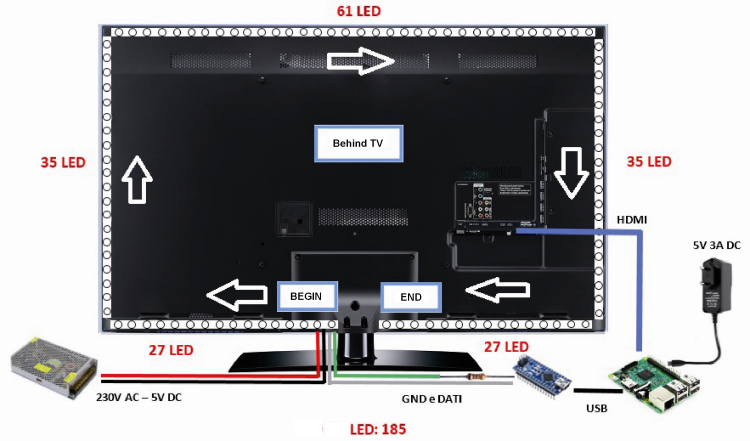
With that said, let’s go back to wiring and elements layout: if we look at the rear panel of our TV we are going to apply our LED strip with its adhesive tape, starting from the bottom left half (if the TV has a central stand), then we continue in clockwise direction along the left edge, the top edge, right and in the right part of the bottom edge.
When we get to each corner, we have to cut the LED strip and connect it to the next segment using pieces of wire we are going to solder in the corresponding pad using a soldering iron no more powerful than 25 W to avoid creases on the strip; once we complete the perimeter, we cut the excess strip following the precut line on each one of them.
Now, let’s connect the two biggest wires of the strip (the black and red ones) to the 5 V power supply, which must be capable to supply a current calculated based on the total length of the LED strip applied on the TV and remember what we said above, that is that 5 m of strip absorb around 8.5 A, therefore if total perimeter is 2.5 m, the current needed will be 4.5 A etc.
Then, we are going to connect the GND contact of the strip to the GND of RandA and the strip’s data wire one of RandA’s pins (we chose 6-pin…) Placing a 470 Ω resistance in the middle.
Let’s take note of how many LEDs we have for each side of our screen and the total number of LEDs: we are going to use these values in a short while when we are going to configure Hyperion (values indicated in images refer to the TV we have used for the project).
After mounting the whole electronics part, let’s download the Hyperion configuration program on our PC (that we can see in figure from this webpage.

Once launched the program, we can see in the main screen all the parameters needed to create the config file; pay attention to the preview image: the front side of the TV will be displayed, while we always have to think as if seeing the TV from the rear side (just like during application of the LED strip).
Here’s the parameters for the “hardware” board:
- Configuration name = this is used to give a name to our configuration;
- Type = Adalight;
- Output = /dev/ttyUSB0;
- Baudrate = 500.000;
- Delay [ms] = 0;
- RGB Byte Order = GRB;
- Direction = counter clockwise;
- LEDs horizontal, left, right = here we are going to insert the specific values for our TV;
- Bottom gap e 1st LED offset = we are going to play with these values to adjust LED interruptions in the bottom edge in case the TV has a stand supported and place the first LED in the correct position.
As for the other boards, we only have to make sure that “Internal frame grabber” and “Kodi Checker” are enabled; we can export the config file JSON with the button “Create Hyperion Configuration” and keep it ready for later when we are going to need it.
Now, let’s download the Boblight configurator (the related screen can be seen in figure from this website.

Let’s open the program and set all the values of the LEDs on the edges using the fields: Top Row LEDs, Right Col LEDs, Left Col LEDs, Bottom Left LEDs, Bottom Right LEDs and Bottom Center Padding; since we have mounted our strip clockwise, in the field Orientation (Rear View) are going to select “Clockwise”.
Let’s now finish the configuration inserting the parameters in the lower part of the program screen:
- Name = this is just to name our configuration;
- Output Device = /dev/ttyUSB0;
- Type = mono;
- Baudrate = 500000;
- enable “Use Magic Word” and we are going to write Ada;
- set Interval to 100000;
- set Open delay to 1.
As you may have noticed, the field “Prefix” fills automatically after we insert all the data; unfortunately, the displayed value is not correct, because Boblight counts LEDs starting from number 1, while Hyperion starts counting from number 0.
In order to generate the exact prefix we have to decrease total number of LEDs by one (we can do it, for instance, by acting on the field “Bottom Left LEDs” and decreasing it by 1): this way, the field “Prefix” will be calculated correctly.
Let’s take note of the Prefix and close Boblight e HyperCon configurators which, if everything goes right, we are not going to need anymore.
Now we are going to download the Arduino’s sketch from this website.
We will open it with Arduino’s IDE and edit the header values:
- STARTCOLOR = starting color, set went Arduino is powered on but it has no color information coming from Raspberry Pi;
- BLACK = black setting;
- DATAPIN = Arduino or RandA pin twitch LED strip data are connected (in our example it’s 6-pin);
- LEDCOUNT total number of LED that we have installed and counted;
- SHOWDELAY = set this field to 1;
- BAUDRATE = set to 500000;
- BRIGHTNESS = max brightness level of the LCD strip, to be set based on the average brightness of the environment where we have our TV (in our example we set it to 100);
- prefix[] = we are going to replace its value with the one generated by Boblight, for instance 41 64 61 00 B8 ED would become 0x41, 0x64, 0x61, 0x00, 0xB8, 0xED.
We are not going to touch the rest of the sketch which, as you can see from Listing 1, waits for the incoming prefix coming from the Raspberry Pi’s serial port and, once obtained, if it matches the one set internally, it keeps “listening” for color data to set on each single LED.
Listing1
#include “Adafruit_NeoPixel.h”
#define STARTCOLOR 0x333333
#define BLACK 0x000000
#define DATAPIN 6
#define LEDCOUNT 185
#define SHOWDELAY 1
#define BAUDRATE 500000
#define BRIGHTNESS 70
const char prefix[] = {0x41, 0x64, 0x61, 0x00, 0xB4, 0xE1};
char buffer[sizeof(prefix)];
Adafruit_NeoPixel strip = Adafruit_NeoPixel(LEDCOUNT, DATAPIN, NEO_GRB + NEO_KHZ800);
int state;
#define STATE_WAITING 1
#define STATE_DO_PREFIX 2
#define STATE_DO_DATA 3
int readSerial;
int currentLED;
void setup(){
strip.begin();
strip.setBrightness( (255 / 100) * BRIGHTNESS );
setAllLEDs(BLACK, 0);
setAllLEDs(STARTCOLOR, 5);
Serial.begin(BAUDRATE);
state = STATE_WAITING;
}
void loop()
{
switch(state)
{
case STATE_WAITING:
if( Serial.available()>0 )
{
readSerial = Serial.read();
if ( readSerial == prefix[0] )
{ state = STATE_DO_PREFIX; }
}
break;
case STATE_DO_PREFIX:
if( Serial.available() > sizeof(prefix) - 2 )
{
Serial.readBytes(buffer, sizeof(prefix) - 1);
for( int Counter = 0; Counter < sizeof(prefix) - 1; Counter++)
{
if( buffer[Counter] == prefix[Counter+1] )
{
state = STATE_DO_DATA;
currentLED = 0;
}
else
{
state = STATE_WAITING;
break;
}
}
}
break;
case STATE_DO_DATA:
if( Serial.available() > 2 )
{
Serial.readBytes( buffer, 3 );
strip.setPixelColor( currentLED++, buffer[0], buffer[1], buffer[2]);
}
if( currentLED > LEDCOUNT )
{
strip.show();
delayMicroseconds(SHOWDELAY);
state = STATE_WAITING;
currentLED = 0;
break;
}
break;
}
}
void setAllLEDs(uint32_t color, int wait)
{
for ( int Counter=0; Counter < LEDCOUNT; Counter++ )
{
strip.setPixelColor( Counter, color );
if( wait > 0 )
{
strip.show();
delay(wait);
}
}
strip.show();
}
Now, we are going to compile and upload the sketch on RandA. Since the RandA board is directly installed on Raspberry Pi everything is more compact. It requires Raspbian operated system to be used with the preconfigured RandA on which we are going to install Kodi.
We will install Hyperion and upload the configuration file JSON previously created on our PC.
HYPERION AND RANDA
Now, let’s download the two-part disk image for RandA:
- RandAV1.5-Raspbian-jessie-2016-05-27-p.zip.001
- RandAV1.5-Raspbian-jessie-2016-05-27-p.zip.002
We are going to unzip the two images and merge them together using a program such as 7-Zip and copy them on a suitable microSD memory card, then we are going to insert the card in the Raspberry Pi’s reader, then power time.

Once the operating system is launched, let’s connect via SSH the program like MobaXTerm and launch the following command:
sudo apt-get update
Next, we are going to install Kodi:
sudo apt-get install kodi
We set Kodi’s autostart by editing the settings file:
sudo nano /etc/default/kodi
Let’s set ENABLED to 1, user=pi e NICE=-10; now we close in save with CTRL + X, then Y and ENTER.
Now we download Hyperion:
sudo wget -N https://raw.github.com/tvdzwan/hyperion/master/bin/install_hyperion.sh
Let’s install it:
sudo sh ./install_hyperion.sh
We are going to transfer, using MobaXTerm or WinSCP, the configuration file JSON (named “hyperion.config.json”) up Hyperion in the path:
/usr/share/hyperion/config/.
Let’s edit it using the command:
nano /usr/share/hyperion/config/hyperion.config.json
And replace the field corresponding to the serial port “/dev/ttyUSB0” with RandA’s one, “/dev/ttyAMA0”. Once finished, let’s close in save using CTRL + X, then Y and ENTER.
Now we are going to edit the startup file for Kodi and also insert the automatic launch for Hyperion:
sudo nano /etc/init.d/kodi
We are going to locate the following code section:
case “$1” in

 start)

   [ “$VERBOSE” != no ] && log_daemon_msg “Starting $DESC” “$NAME”

   do_start

   case “$?” in

     0|1) [ “$VERBOSE” != no ] && log_end_msg 0 ;;

     2)[ “$VERBOSE” != no ] && log_end_msg 1 ;;

       esac
Between “do_start” and “case “$?” in” we are going to insert the line below:
/usr/share/hyperion/bin/hyperiond /usr/share/hyperion/config/hyperion.config.json
Now we close in save using CTRL + X, then we press Y and ENTER.
We are now going to mount RandA on Raspberry Pi, we upload Arduino’ sketch using the command ArduLoad or with Arduino IDE preinstalled; then we are going to turn off the Raspberry Pi, disconnect the power supply and reconnect it to RandA: Kodi media center will automatically launch, the animation with the rainbow colors will be displayed and your system is up and running.
In this case, on our website you can download the ready-made image for Raspberry Pi with RandA: all you have to do is change Hyperion’s configuration and the sketch values of RandA in order to use it in our application.
TROUBLESHOOTING
If, after launching Kodi, you don’t see the lighting effect with the rainbow colors, it means that Hyperion cannot communicate with RandA; there are mainly two possible reasons for this: a wrong baud-rate value (on the sketch or on the configuration) that, allow us to remind you, must be set to 500000, or a wrong prefix.
In the first case, you need to reopen Arduino’s sketch and the configuration window of Hyperion and check that the two baud-rate values are the same; in the second case, on the other hand, you need to reopen Boblight configurator and set all the values in order to generate the prefix, and remember that you need to take off one LED from one of the sides in order to get the correct prefix. Once done that, insert the prefix in Arduino’s sketch and upload it. Reboot your Raspberry Pi after every modification of the configuration file or the sketch and, if it still doesn’t work, carefully go over all the configuration parameters inserted in HyperCon and make sure they match exactly those found in this article.
SYSTEM CUSTOMIZATION
In some cases, you might want or need to adjust the colors of the RGB LEDs in order to make the lighting outline identical (in terms of color) to the one determined by the colors projected by the screen of your TV; in order to adjust the color you can open HyperCon, go on the “Process” tab and change the value in the “Color Calibration” section: with each modification you will need to generate the JSON configuration file again and then copy it on the Raspberry Pi. You can also launch an SSH connection to Hyperion directly from HyperCon; for this you need to go on the “SSH” tab and set here your connection data (system, IP, port, username and password) and then click on “Connect”. Once you establish a connection you can send the configuration file directly from this program and change the LED colors in order to check that they actually match after calibration. On the other hand, on the “External” tab, you can change settings for that part of Hyperion connecting to Kodi and analyzing video, you can enable or disable the LEDs in the various program sections such as manual, video, screensaver…

If you scroll down, in the “Booteffect / Static Color” section, you have the possibility to change the effect or the static color executed when Hyperion connects to Kodi (with each launch): as default we will find the rainbow-colored animation, with its duration. Well, with that said we can call it a day; all we have left to do is hope you will enjoy this project!
From openstore
Raspberry Pi 3 Model B with Wi-Fi and Bluetooth
SWITCHING POWER SUPPLY 5V DC 130W
RandA: the union from Raspberry and Arduino

[…] RASPILIGHT: an open project for Ambilight TV effect – [Link] […]
Hi- What changes can be made if I want to use other HDMI sources, besides Kodi ? Example using my apple tv ?
[…] RASPILIGHT: un proyecto abierto para el efecto Ambilight TV – [Link] […]