
8 relays controlled by 8 opto-isolated digital lines or by Raspberry Pi.
It’s not the first time that we propose a relay board, because in these pages you have found both generic control boards that can be driven with voltage levels and logic states, and specific boards for use with Arduino. Still, surely the project we describe in these pages is a new one: it is, in fact, a relay board -and so far nothing new- but equipped with a plastic support that allows its mounting in the DIN rail (omega bar) of standard switchboards, as well as a connector to house a Raspberry Pi board. So, it is a universal relay module that can be used alone and controlled by logic levels by wiring the terminal blocks corresponding to its inputs, i.e., directly from the Raspberry Pi onboard that can act as a home automation control unit, but also as an industrial controller. Because of modularity, the board can be sectioned by cutting away, where you want to use it as a simple opto-isolated relay module, the portion of PCB that would house Raspberry Pi, to reduce the space in the electrical cabinet.
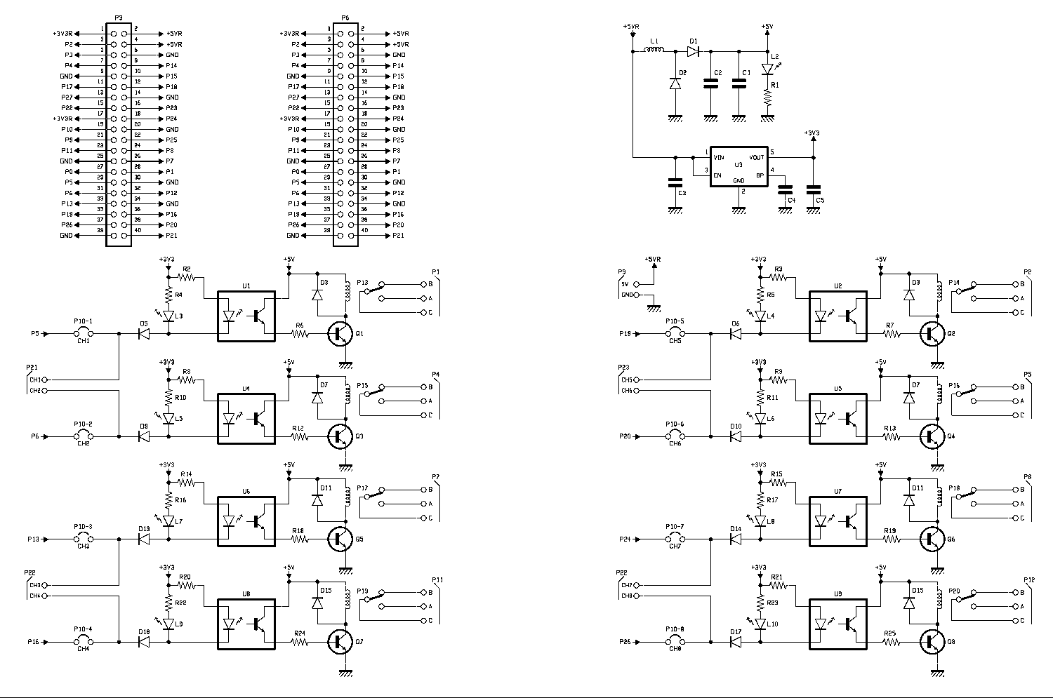
But let’s take a look at the circuit by analyzing the wiring diagram, which you can find in these pages.
Wiring diagram
The circuit itself is very simple because it consists of eight identical stages, each of which is made up of a split input line (to receive the TTL signal from Raspberry Pi or the input terminal block) that can be cut by jumper, by an opto-isolator that transmits the command optically while maintaining galvanic isolation between the inputs (or the Raspberry Pi board) and the relay coil, a status LED and a common emitter configured transistor connected to Darlington with the respective phototransistor. The set is powered through the input terminal block, with a voltage of 5Vdc that also reaches the Raspberry Pi headers and a power supply block with a 3.3V voltage regulator.
Let us, therefore, analyze a section of the circuit corresponding to a channel, and it is understood that what has been stated for this one is valid for all the seven remaining channels: the input signal can come both from the input terminal board where P21 carries the commands of channels 1 and 2, P22 those of channels 3 and 4, P23 those of CH5 and CH6 and P24 the command signals of channels 7 and 8. The same row of terminals receives the power supply, attested to P9 (5V and ground).
As for channel 1, which is the analyzed channel, the command comes from the IN CH1 terminal referred to mass, i.e., P5 of the Raspberry Pi header. The CH1 jumper allows you to provide the command from Raspberry Pi, i.e., to transport to the P5 line of the latter, if it is configured as input, the signal eventually provided by the terminal board.
At high level (means input voltage at least equal to 3.3V positive), i.e., open line, the internal LED of the photocoupler remains blocked, and the external LED of the monitor (L3) also; instead, they both light up if the input is closed to ground or brought to zero volts when the diode D5 drags pin 2 of the photocoupler to 0.6V more than the input. The D5 diode protects the circuit in case an excessive positive voltage is applied and allows the input control by circuits operating at a voltage higher than the 3.3V that supply the input section of the board; in fact, it leads only when the potential on the cathode is lower than that of the anode by at least 0.6V, so if the voltage is higher, this is equivalent to leaving the input open.
However, when the input is voltage-free or at high level, the photocoupler is at rest and the NPN phototransistor at its output also, so that the pin 3 is at zero volts and the transistor Q1 is interdicted; in this condition, the relay is at rest and the common contact (C) is connected to the normally closed (B).
On the other hand, when the input is grounded or at a potential lower than 2.7V, the LED inside the photocoupler lights up and pushes the output phototransistor into conduction, a condition highlighted by the illumination of LED L3; now the pin 3 of U1 goes to about 4V and polarizes, through the resistance R6, the base of Q, making the latter go into saturation, so that the collector current of this NPN feeds the coil of the relay (P13) whose mobile crew closes the exchange between normally open (A) and common (C).
We conclude the analysis of the wiring diagram with the power supply block, which starts from terminal block P9, to which (between terminal +5V and GND) 5V stabilized, which are then filtered by the inductance L1 and pass through the reverse polarity protection diode D1, reaching the +5VR line, well filtered by the multilayer ceramic capacitors C1 and C2; In truth, at the +5V input there is a second protection diode against voltage inversion, that is D2, which, however, does not block the current, but rather short-circuits it if it is in the opposite direction. This diode also and above all has the function of switching off any inverse voltage impulses due to the presence of the inductance, when you go to deprive the power supply circuit.
Let’s go on and see that the +5VR line feeds the Raspberry Pi headers and therefore this board, where it is mounted, in addition to the LDO U3 regulator (a Richtek RT9193-33) which is used to obtain the 3.3V stabilized for the input stages of the opto-isolators, delivering a maximum of 300 mA, more than enough to operate the eight photocouplers and their external LEDs.
It should be noted that the +3V3 line is limited to this and has nothing to do with the 3.3 volts Raspberry Pi, which not surprisingly on the headers is marked +3V3R to distinguish it; the distinction of the two lines is a must because the two circuits must remain distinct since the Raspberry Pi board has a 3.3V regulator inside and it is not advisable to combine the output of the latter with that of U3.
Raspberry Pi configuration
Once the board is plugged into the respective headers, you will first need to configure the Raspberry Pi board to be associated with the 8 relay interface, so we recommend that you make the essential connections to the Raspberry Pi so you can configure the IP address and some other parameters.
Then you have to connect a monitor via HDMI cable, then connect the LAN cable and a keyboard and mouse.
Once this is done, prepare a micro SD card of at least 16GB with the NOOBS operating system loaded (we recommend you always use the latest available version downloadable from www.raspberrypi.org/downloads) and insert it into the appropriate slot on the Raspberry Pi. About downloading the image, remember that you must download the ZIP file of what is classified as “Offline and network install” (Fig. 1). Once downloaded, you have to unzip the contents of the ZIP file directly on microSD.
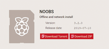
Fig. 1
Now connect a 5V/3A power supply to the Raspberry Pi’s MicroUSB connector and complete the NOOBS installation procedure. During the final installation procedure, if a WiFi-equipped Raspberry Pi has been connected, you will be given the option to pair it with an available WiFi hot-spot, so if you wish, please enter the required information. If you choose this option, the LAN cable can then be removed after installation is complete.
Once you start the operating system, you will have a Desktop mode view that will allow you to use the system, but especially in our case, it will allow us to configure the system parameters.
First of all, before proceeding to the system configuration, you have to check the availability of internet connection, so start the browser using the button highlighted with the red rectangle in Fig. 2 among those in the toolbar at the top of the screen.

Fig. 2
If navigation starts and runs smoothly, you can proceed with the configuration by following the steps below:
1. start the terminal using the icon in the usual toolbar, highlighted with the red rectangle in Fig. 3.

Fig. 3
2. run the command “ifconfig” through the terminal program and retrieve the IP address of the board through it.
If the connection is via cable, you will be able to get the IP address purchased from the Raspberry Pi in the network under “eth0”, or under “wlan0” if the connection is via WiFi (in our case the assigned IP is “192.168.0.116”);
3. close the terminal;
4. From the main operating system menu, go to “Preferences > Raspberry Pi Configurations” (Fig. 4);

Fig. 4
5. from the “System” tab check “Login as user ‘pi'”; the default parameters are (Fig. 5):
user: pi
password: Raspberry

Fig. 5
6. from the “Interfaces” tab enable the “SSH” and “Remote GPIO” entries by clicking on the enabled radio button, the remaining entries do not need to be enabled;
7. close the window by clicking “OK”;
8. reboot the operating system from the “Shutdown” menu.
Managed by raspberry Pi
The board with 8 relay outputs can be managed directly from the operating system in a variety of ways, as the Raspberry Pi offers several possibilities. Some examples of code can be downloaded directly online from the product sheet. Inside the compressed file that you will download, you will find 5 folders containing examples in different languages. In our case, we will only focus on bcm2835 and python folders, as we are interested in control directly from Raspberry Pi.
BCM2835
This code is based on the BCM2835 library which is not resident in the Raspberry Pi operating system, so as it is an external resource it is necessary to install it; for this purpose run the commands:
pi@raspberrypi :~ $ wget http://www.airspayce.com/
mikem/bcm2835/ bcm2835-1.58.tar.gz
pi@raspberrypi :~ $ cd bcm2835-1.5;
pi@raspberrypi :~ $ cd bcm2835-1.5;
pi@raspberrypi :~ $ ./configure;
pi@raspberrypi :~ $ make;
pi@raspberrypi :~ $ sudo make install
Once the resource is installed in the operating system, you can try the example in the folder “bcm2835”. Since the folder with the examples has been copied to the operating system desktop inside the “RPI” folder, type the following command to access the folder:
pi@raspberrypi :~ $ cd ./Desktop/RPI/bcm2835
The proposed example has already been compiled, so it is ready to use, in any case, if you decide to modify the source code you can do so with the command:
pi@raspberrypi :~/Desktop/RPI/bcm2835 $ sudo nano relay_demo.o
When the change is complete, you can run the following command to remove the previous compilation:
pi@raspberrypi :~ /Desktop/RPI/bcm2835 $ sudo make clean
Recompile the code edited through the command:
pi@raspberrypi :~ /Desktop/RPI/bcm2835 $ sudo make
To run the demo and/or modified code, enter.
pi@raspberrypi :~ /Desktop/RPI/bcm2835 $ sudo ./Relay_demo
To finish the execution, simply press the “CTRL + z” key combination.
The phyton code
No special libraries are needed to run this example, so simply run the source in the “python” directory. The example has already been compiled, so it is ready to use; however, know that if you want, you can modify the source code with the command:
pi@raspberrypi :~/Desktop/RPI/python $ sudo nano Relay_demo.py
When the change is complete, you can directly execute the code written by typing:
pi@raspberrypi :~ /Desktop/RPI/python $ python Relay_demo.py
To finish the execution, simply press the key combination “CTRL + z.”
Direct management from terminal
You can manage the relays from Raspberry Pi without having to know any programming languages: just type directly on the terminal, the command that allows you to set the status on a GPIO of Raspberry Pi. In this regard, we remind you that the 8 outputs are directly connected to the following GPIO:
Output 1: I/O 05
Output 2: I/O 06
Output 3: I/O 13
Output 4: I/O 16
Output 5: I/O 19
Output 6: I/O 20
Output 7: I/O 21
Output 8: I/O 26
For example, to activate the first output and then energize the relay, you would need to enter.
pi@raspberrypi :~ $ gpio -g write 5 1
To bring the same relay to rest, you will have to type:
pi@raspberrypi :~ $ gpio -g write 5 0
If, on the other hand, you would like to read, for example, the status of the output under examination, you will have to write:
pi@raspberrypi :~ $ gpio -g read 5
Management from lan via web page
In addition to directly from the Raspberry Pi operating system, we can manage the relay board from a local network and no longer directly from a Raspberry Pi user; for this purpose, we will look at the Python-Bottle example, which allows us to manage relays from a local network by accessing from a dedicated web page.
Bottle is a lightweight and efficient micro Python framework. It is distributed as a single module and has no dependencies other than the Python standard. Installation in the system is required to run the demo code.
Follow the next commands to install the module:
pi@raspberrypi :~ $ sweat apt-get install python-bottle
Once the module is installed, everything is ready to run the demo code in the “python-bottle” folder. Since the folder with the examples has been copied to the Operating System Desktop inside the “RPI” folder, type the following command to access the folder.
pi@raspberrypi :~ $ cd ./Desktop/RPI/python-bottle
The proposed example has already been compiled, so it is ready to use, in any case, if you decide to modify the source code you can do so with the command:
pi@raspberrypi :~/Desktop/RPI/python-bottle $ sudo nano main.py
The example proposed here relies on an HTML page created in a very simple way to allow the management via WEB of the 8 outputs, so you can change the graphic aspect at will by going to modify the file “index.html.”

To execute the created code and start the management server, I will need to run the command:
pi@raspberrypi :~ /Desktop/RPI/python-bottle $ sudo python main.py
Fig. 6 shows what will be displayed when the command is executed. The last line indicates that a device with IP 192.168.0.88 in the network had access to the board.
This will start the server, which will remain active until you decide to end the program via “CTRL + z.”
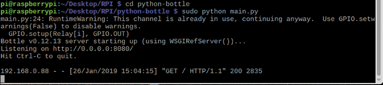
Fig. 6
At this point, it will be sufficient from a browser in the same network, type in the IP address of Raspberry, to access the 8 output management web page. This operation can be performed by a Smartphone, Tablet, PC.
The listening port of the example proposed here is the 8080, so in the browser, since our Raspberry as configured has IP 192.168.0.116, you must type http://192.168.0.116:8080.
Google Chrome, for example, will display what is proposed in Fig. 7.

Fig. 7
Management from lan via app
Several third-party apps allow you to manage GPIO via SSH of the Raspberry Pi freely. Since, in our case, the outputs are connected directly to GPIO, Apps of this type are convenient and do not require special knowledge for their configuration.
First, download the “RaspController” app from the Store from your smartphone or tablet.
There are two versions of this App: the free one that involves free use, but with some advertisements that appear during the use of the App; if the advertisements are annoying, you can decide to buy the App for a fee, maybe after trying the free one. For Android, you can also download the free version via the QRcode you see in Fig. 8; as for iOS, the app is currently not available.

Fig. 8
Now you will need to configure the App remembering the following data reported in the previous pages which are summarized below for your convenience:
User: pi
Password: Raspberry
IP address: 192.168.0.116
SSH door: door 22
Now let’s go through the configuration steps.
1. Start the App.
2. Press on the “+” button at the bottom right to add the Raspberry board (Fig. 9) and then on Edit Device, introducing the following data in the window (Fig. 10):
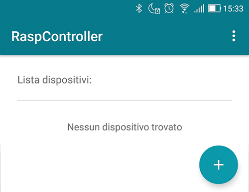
Fig. 9
Device Name: Raspberry 8CH
Host Name: 192,168,0,116
SSH port: 22
Timeout: 10
Username: pi
Authentication: Password
Password: Raspberry

Fig. 10
3. To verify that the Raspberry Pi is responding correctly, press the “CONNECTION TEST” button. If all parameters are correct, the test will be successful, as shown in Fig. 11.
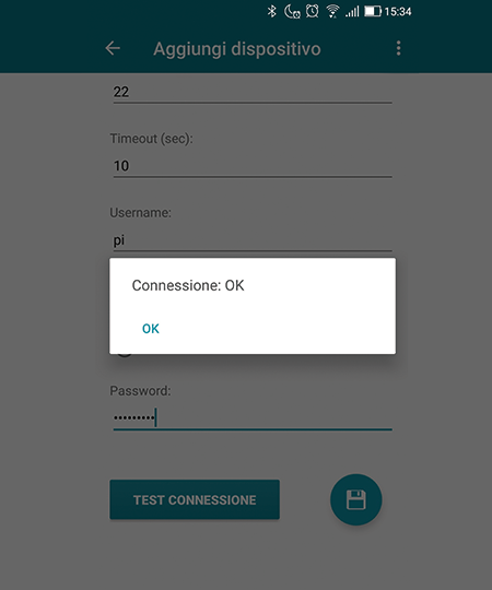
Fig. 11
4. Tap on “OK” and then on the floppy disk symbol, to save the configuration and return to the previous screen, where you will be able to verify the insertion of the board we have named “Raspberry 8CH” (Fig. 12).
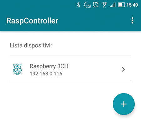
Fig. 12
5. With a simple tap on the arrow “>” or the name, you can access the management of the board itself (Fig. 13). As you can see, you can do a lot more than we’re looking at. For example, you can manage GPIOs, check the performance of the board, access the file manager to manage files on the Raspberry, send commands through the shell, access the Raspberry camera, etc. The app offers many features that we will not exhaust in this article. Still, we recommend you to try them out.

Fig. 13
6. With a touch on “GPIO Control,” you can access the GPIO management of Raspberry, which will allow you to activate or not the outputs on the board. The App hasn’t been completely configured yet, so at first, you can see only 4 GPIOs configured by the App creators, but with the simple modification, you can insert 8 outputs, and above all, you can also assign a name to each of them (Fig. 14).

Fig. 14
7. Press the wrench symbol in the lower right corner to access the configuration area of the App that will allow you to activate the 8 GPIOs used on the base board (Fig. 15).
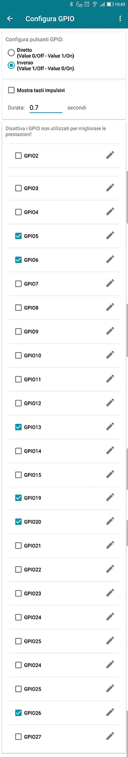
Fig. 15
8. Now you will have to change some parameters to activate only the GPIOs used, i.e., the 8 output control ports.
9. Press the arrow at the top left of the screen to go back. The screen with the output buttons will update according to the settings made. If you see some buttons called “IN” instead of “OUT” just plug over the “IN” to convert this GPIO to output. Pressing “0” will activate the output in a bistable mode, and “1” underlined “salmon” will be shown to indicate activation. If the third icon is pressed, the output will switch to monostable mode according to the time chosen in the “GPIO Configuration,” which by default is 0.7 seconds. In case you decide to close the App, restart the phone, then opening the App will read the status of the outputs and show the one they are currently in (Fig. 16).

Fig. 16
Conclusion
The relay board is very versatile both in terms of installation (because it can also work stand-alone) and in terms of control from Raspberry Pi, which can be done, as we explained, from the console or remotely via LAN or Internet. You are sure to find the application that best meets your needs.
From openstore
Raspberry Pi 8-ch Relay Expansion Board

Salve, sarei interessato ad acquistare questa scheda, ma mi servirebbe con i relé da 10 ampere