
LCD color and high-performance touch screens can work with Arduino here is how to use them.
Arduino has become the most famous open-source hardware and software development platform in the world, by virtue of its potential and ease of use. As you well know, simply connect it to the Personal Computer with a USB cable to be able to use the board immediately (for example by enabling the serial with the Arduino IDE or with a terminal). We can connect to Arduino many electronics, sensors, breakout boards, directly or through the well-known shields that accompany it.
But if we wanted to interact with the Arduino board via a touch-screen display, how could we do it? Or rather, the market offers a varied typology of solutions that can sometimes complicate the choice; some use I²C protocols, others SPI, others still communicate via RS232 or TTL serial channel.
We must also keep in mind how to upload the images and finally, more importantly, how to correctly manage the event of the touch touched.
If you have come to these questions and are wondering how to interface Arduino boards or similar development boards with a latest-generation display, and you don’t know which way to start, we have found the solution to your problem and we propose it to you in this article, where we take this opportunity to present the latest generation displays of the Nextion series (Fig. 1).
The objective of this article is manifold: first of all we will show you the advantages of these displays, then we will show you how to configure a specific display at first start, download the necessary resources and physically connect the latter to an Arduino board.
Finally, we will try to create a simple interface on the display with buttons to operate the Arduino GPIOs by simply pressing the touch screen.

Fig. 1
Why choose nextion?
Nextion is an HMI (Human Machine Interface) product that combines a TFT touch display with an integrated processor and memory; to communicate with the MCU (for example Arduino) it uses the TTL serial, it also allows ASCII text-based instructions to encode the way the components interact on the display.
It offers two update modes, the first by connecting the USB cable to the PC with the TTL-RS232 adapter and the second via SD-Card (in this mode it is inserted at the first power on and is removed after the update).
On the market, Nextion displays can be found in various formats, ranging from a minimum of 2.4 “(inches) up to 7” (inches) and they have also developed two types of versions: The Basic and the Enhanced versions. The latter, compared to Basic, has more:
- a built-in RTC (Real Time Clock) with buffer battery housing;
- supports saving data on Flash;
- supports GPIO (in this case it is possible to use the display without Arduino to be able to drive outputs or read inputs);
- has a higher flash capacity and a functioning CPU with a higher frequency clock.
The display that we will show you has a size of 2.4 “corresponds to the Basic version, since we have to use it via the serial protocol and therefore we will use the Arduino GPIOs.
To start the demonstration, we need to get the following components:
- Nextion display with USB cable;
- Arduino mega with USB cable;
- 4 male / female jumpers;
- USB-TTL converter
- Nextion editor software.
Let’s start working with nextion
So let’s move on to using these displays and take it for granted to work in a Windows environment and that you have already installed and used the Arduino IDE software on your PC; this is because, in order to communicate with the display, a special sketch must be loaded into the Arduino.
If you are using it for the first time, we refer you to the official Arduino website (www.arduino.cc) where you can find all the guides and examples to make the best use of it.
To design the graphical interface, the manufacturer has designed software called “NEXTION Editor” free and downloadable from the site https://nextion.itead.cc/ which allows you to quickly develop the GUI with the simple drag and drop method. release components (e.g. graphics, text, button etc.).
It also has the debug function, which can also be used without a display to design all the graphics by performing a simulation of the latter; even you can also press the buttons with the mouse, simulating the touch screen pressure and display the command that will be sent via serial.
We then proceed to download, selecting the Nextion Editor command on the Nextion website, accessible from the Resources item of the header menu, which gives access to the Download submenu, as seen in Fig. 2; we then install the software on the Personal Computer.

Fig. 2
Once the Nextion Editor software is installed, we create the interface that we will use. The Editor is very simple and intuitive to use, so let’s start by selecting the File / New item at the top left and assigning a name (for example “test”) to our project.
As we see in Fig. 3, a menu will appear on the screen that will allow us to choose the size and version of the display used.
In our case, in the DEVICE item we select the basic 2.4-inch one (if you have another type of size just select it); you can also decide the orientation under the DISPLAY item (Fig. 3).

Fig. 3
By clicking on OK a white box called “PAGE0” will appear; thanks to the drag/drop method (select component with the left mouse button and release it in the white box) insert two components “Button” and a “Text” in the box as shown in Fig. 4.
On the right side of the editor we can see the “Attribute” category (see the usual Fig. 4); here change the “objname” parameter to assign a name to each inserted object: for example, the “text” object is renamed to “title”, the first button to “Turn on” and the other to “Turn off”.
As you can see, in the menu there are many other methods that can be implemented: for example, changing the colour of the font used, the font size, the coordinates, therefore you can customize the objects as you see fit.
If you want to change the background with a colour, simply click with the mouse in a point of the box (provided that it is not the one where we have inserted the objects): the “Attribute” category will automatically load the methods of the page (PAGE0); we verify that in the item “sta” there is set “Solid colour” and in the item “bco” select “more colour”.

Fig. 4
Once this is done, a pop-up will appear offering a colour palette: choose the one you prefer and click OK. The result must be the one shown in Fig. 5. Note that it is also possible to insert images as a background; to do this, just change the method.
Once the menu is completed and customized, we click on the “Debug” button (top toolbar) which will launch a window where we will see the result of our menu; from here we can finally load everything on the display.
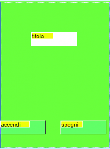
Fig. 5
It is possible that at the first compilation (debug) errors may appear; this is due to the font that is not loaded, so select the item “Tools / Font generation” (toolbar) and set, for example, “Arial” giving a name to the font “Example Arial” and click on “Generate font” as shown in Fig. 6; then a Windows pop-up will open asking where to save the font. Here select a workbook and name the font.
Finally, the editor will ask us if we want to load the font into the project: we respond by clicking “Yes”.
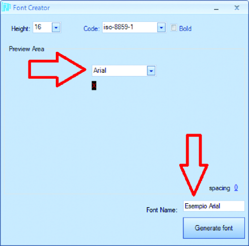
Fig. 6
If the font has been loaded correctly, by clicking on the “Update” button in the font box at the bottom left we will have to display the font we added in position 0 (Fig. 7). At this point, it will be necessary to click again on “Debug” and check that this time there are no errors.
We close the “Debug” and see how to add a string to Arduino every time a button is pressed on the display; to do this we select the first “Turn on” button with the mouse and in the “Event” box we only put the tick in “Touch Press Event” “Send Component ID”.
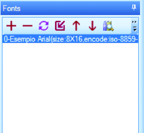
Fig. 7
We also do the same with the second button and finally click on the “Debug” button again.
As we can see in Fig. 8, every time we click on a button in the debug area, the editor will show a string, which will be logically different for each button.
The string will be sent to the serial port and then from the display to the Arduino board.
What we need to do now is to load a code in Arduino that allows the board to understand the received string and to turn on or off a GPIO line (for example the one corresponding to the LED on the Arduino board) or to make it switches from 0 to 1 logical and the other way around.
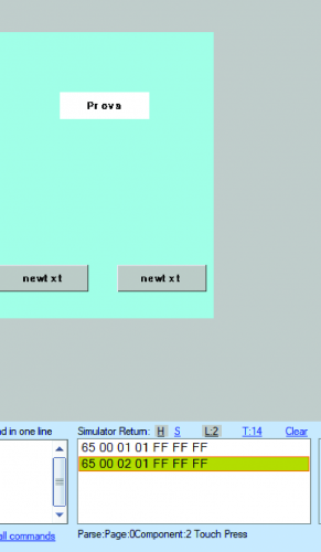
Fig. 8
Let’s deal with the hardware
Now it’s time to work on the Nextion display in order to prepare it to interact with our Arduino; first connect the USB / TTL converter to the touch panel as shown in Fig. 9 and finally insert the USB cable connector into the USB socket of the Personal Computer. The USB / TTL converter used is of the type that allows you to power the display because it provides a 5-volt output. We specify that the connections to be made are as follows:
- + 5V output of the converter to the 5V contact of the display connector;
GND of the converter to GND of the display connector;
- TX output of the converter goes to the RX of the display connector;
- RX input of the converter to TX of the display connector.
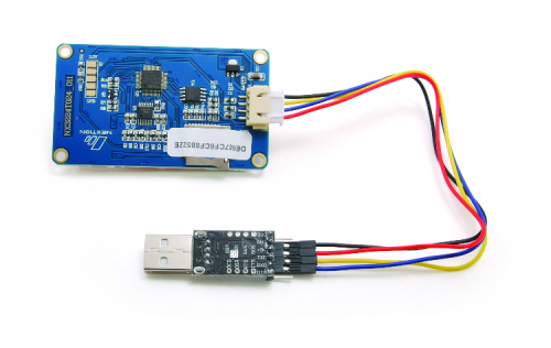
Fig. 9
Now in the debug menu we click on the “Operation” button and choose the “Upload to nextion” option.
As shown in the image in Fig. 10, a dialogue box relating to the communication ports will be shown on the screen; here, clicking on Com Port will open the drop-down menu where you can set the port and the baud rate. Note that choosing the Auto search menu command will automatically detect the virtual COM port to which the display has been connected via the USB / TTL converter.
Pressing the “GO” button will start updating the display and display the new software created by us with the two enabled buttons.
We disconnect the display from the PC and move to the Arduino side to instruct it to acquire the display commands.
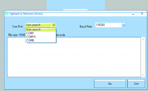
Fig. 10
We load the code on Arduino
We have created an example sketch for you which is available in the article files, this will allow you to immediately try the display without having to configure everything that has been explained so far.
To use the example you have to upload it, therefore connect Arduino to the Personal Computer via the usual USB cable and open the IDE; here you have to open the file (File / Open) and from the Tools menu, click on Tab and, from the submenu that opens choose Arduino mega. Then set the correct “COM” and finally click on the Upload button.
The code you are going to load will allow Arduino to receive the commands sent from the display from the serial port when we press the touch buttons on the display itself; if the parsing of the “turn on” command is correct (hexadecimal code 65 00 01 01 FF FF FF), the LED on the board will light up, while with the “turn off” command (65 00 02 01 FF FF FF) it will turn off again.
The code that does all this can be found in Listing 1, opposite.
Listing 1
void setup() {
pinMode(LED_BUILTIN, OUTPUT);
digitalWrite(LED_BUILTIN, LOW);
Serial.begin(BAUDRATE_SERIAL); /*baudrate serial*/
delay(10);
Serial.flush();
}
void loop() {
if(Serial.available()>0) {
char inChar = (char)Serial.read();
if (idx< STRING_MAX) { /*clean the buffer*/
inputString[idx]=inChar;
idx++;
}
if (idx>6)/*sif I have more than 6 characters received I parsing
{ stringComplete=true; }
}
parse_menu(); /*Parsing received commands*/
}
void parse_menu() {
uint8_t index=0;
if (stringComplete) /*I received a string*/
{
delay(2);
index=strlen(inputString);
if((inputString[0]==0x65)&& (inputString[1]==0x00))
{
if(inputString[2]==0x01)
{ digitalWrite(LED_BUILTIN, HIGH); }
else if(inputString[2]==0x02)
{ digitalWrite(LED_BUILTIN, LOW); }
}
for(idx=0;idx<STRING_MAX;idx++) /*clean the string */
{ inputString[idx]=0; }
idx=0;
stringComplete=false;
}
}
We connect Arduino to the display
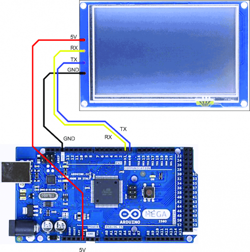
Well, now that we have also experimented with the application example and tested the operation of the display, we can move on to assembling the hardware which is then the goal of this article.
Therefore, we proceed by connecting the display to Arduino and supplying it with power, as illustrated in the wiring diagram proposed in Fig. 11; as you can see, the Arduino + 5V and GND (which in the case of the image is a MEGA) feed the touch-screen, while the hardware UART is used for communication, connecting the Arduino TX to the RX of the touch panel and the RX of the latter to the TX line of the Arduino MEGA UART.
Starting from our example, you will be able to create drive systems with touch interface; for example, you can add customized buttons on the display, with the management of the button pressed or, for example, release (by sending the command) and finally load the new project into the display. Whenever a command is added to the display, remember that through the serial you will also have to modify the example loaded in Arduino, adding in the reception parsing the new commands received to operate other GPIOs (also in this case you will have to upload the firmware to the Arduino board).
Conclusions
We remind you that compared to other touch displays on the market, Nextion’s offer allows you to better cover all aspects of the design that concern the user interface. Furthermore, with the “nextion enhanced” version, it is possible to program the display directly by means of a code (pseudo-C proprietary Nextion) without using Arduino and to operate the GPIO available directly from the display (for example, a relay can be connected directly to the display). We leave to you the discovery of the additional features offered by these high-performance displays of the latest generation and their experimentation, reminding you that on the website there is documentation useful to deepen those aspects that we have not been able to here, for reasons of space and cutting of the article, “rattle off”. So, we just have to wish you good work in developing your applications.
From openstore
