
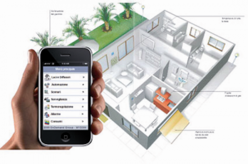
Everyone likes comforts, you know, and that is why we all prepare ourselves, as soon as we can, to automatize some functions that otherwise we should manually carry out, thus inevitably taking up time and energies: from the irrigation system, to the tent that comes back automatically if too much wind rises; to the remote heating control for the holiday house; to the lights of the walkway that are turned on once we come back home. For all of this we may use the term domotics, that indeed indicates all the automatisms that are present in a house or, more in general, in a building. Different systems are available on the market, to realize a domotic house, and it is not difficult to find even some installation using a bus technology: this one allows to connect and control every single element of the domotic system.
The direction that domotics is taking in the last times is the one bringing to the substitution of the bus with a wireless network, one in which every intelligent element exchanges information via radio. The main benefit lies in the wiring reduction, and consequently of the installation times, but it is equally tempting to have the possibility to create moving points that can be repositioned within the house to your liking. One of the products that is making its way in the sector of wireless domotics is RFTide, by the italian firm Aurel.
The RFTide network

The RFTide products are born for the development of small mesh networks at 868 MHz, that are easily installed and mantained, and are mainly destined to domotics for houses interior, but also to telemetry and to smart-energy solutions. The main usage resides in the management of tents’ openings and closings, in the brightness control for LED installations, in the sensors reading, in the actuators’ state detection. Even though the system is essentially born to be integrated in domotics, it can be applied to security, since it allows to monitor systems for the premises, perfectly integrating itself with the dedicated Aurel sensors, and allowing to realize sophisticated wireless alarm systems, that maybe can be connected to the web to carry out remote monitoring and to remotely manage the various functionalities.
A network is made up by one or more Master units, that can be operated by remote control, and by a series of Slave units interfaced with actuators or sensors in general.
A RFTide network is formed by two main device classes: Master units, that send commands (they can be acquisition commands, or operations execution commands) and Slave units, that form the network nodes. Besides the dedicated Aurel remote control, the commands can actually be sent by other systems that are interfaced with the network, such as smartphones or Personal computers, by means of an access point called Gateway.
The RFTide network takes into account two transmission types: the one marked by a Master unit (typically, a remote control) that sends to the network the commands that have to be executed by the Slave unit; and the one originated by a Slave unit and directed to the Master unit, that contains the data that is directed to this last one and concerns, for example, a reading acquisition.
If the Master unit is connected to a computer, the command may contain a query concerning the state of the Slave unit, or a sensor that is connected to it, or the value of a quantity that is measured, for example a temperature; in this last case the Master unit doesn’t send activation commands to the users, but becomes the data transport vehicle from a potential computer and to it, or to another system connected to the Master unit.
The Slave units are of various kinds: they may activate electric users by means of relays or they may acquire data concerning the measure of the temperature, or other information from the sensors. The RFTide network works at 868 MHz, a frequency band in which Aurel has a solid experience, and in which are operating less systems than in the classic ISM at 2,4 GHz; this allows a less noisy communication. Moreover, by operating at a lower frequency, the losses are smaller than at 2,4 GHz, thus the electricity consumption from the devices is reduced in comparison to the ones working with the ZigBee standard.
As with ZigBee, in RFTide it is possible to realize the communication between nodes that do not “see” each other directly, by taking advantage of the mesh network: in practice, the data sent by the Master units towards the Slave units can be repeated by other Slave units, or by dedicated devices called Repeaters. Therefore, when a Slave unit intercepts a radio signal containing data according to the RFTide protocol, if such data contains a direct command the Slave unit will execute it, otherwise it will send it again to the network. Similarly, if a Slave unit intercepts data sent by a similar unit and directed to the Master unit, it then sends it again to the network.
Precisely because of this operating mode, the RFTide network admits the existence of moving nodes, which is essential if you want to use a remote control from any point of your house.
The main element of a RFTide network is a Master device, to which many nodes (Slave units) can be associated.

The basic RFTide module
The Master and Slave units are based on the same base RFTide module; the distinction between Master and Slave units is made depending on how the base module is used. The RFTide module is formed by a RF transceiver at 868 MHz, interfaced with a microcontroller, that makes available to the exterior the two GPOUT (General Purpose Out) output lines that can be used to command loads by means of transistors or line-drivers; and two GPIN (General Purpose In) digital lines to acquire logical levels. The RF stage is a transceiver at 868 MHz, capable of a reception sensitivity of as much as -100 dB, and of a power transmission for +7 dB.
Aurel produces RFTide modules in two versions, that are distinguished on the basis of the power supply voltage: those at 5V are destined to applications powered by the 220 V ca. network; while those at 3V have been designed for battery powering. The absorptions are very low: only 33 mA when sending and 10 mA when receiving; a Standby mode is also provided, and with that the absorption goes down to 4 μA. In the 3V version, the two input lines can be set up to read analog voltages.
To create a Master unit, it is necessary to use a basic RFTide module, that is provided with an univocal serial number identifier (a 4bytes NetworkID): this one is assigned during the making and that cannot be modified; in this case we talk about “serialized modules”. Each Slave unit, on the other hand, has a predefined 0x0000 address and, during the association phase, it assumes the value taken by the Master unit as NetworkID, by copying the new value in the non-volatile internal memory. Only modules with the same NetworkID may communicate between them, nonetheless it is possible to copy the serial number from a Master Remote Control to another, so that the two may be part of the same network. For the sake of completeness, we shall say that each module can be configured as a Master unit, but if it has not been serialized by a manufacturer, it will have a non modifiable 0x00 value as NetworkID, and any node associated with it will always have a NetworkID value of 0x00. In this case the network, even though working correctly, will not be univocal and there might be some interference with nearby networks that have been created in the same way.
The assignation of an univocal code to each Master unit and then to the network that is coupled with it, allows to put in operation more networks within the same radius of action and therefore to avoid interferences, for example, between nearby apartments. It is not possible to clone existing networks or to interfere with existing networks, if not by copying the Master’s serial number that has configured the network into another Master unit: such an operation can be executed only if having the physical availability of the Master to be cloned.
An interesting thing concerning the RFTide network is that each node may communicate directly with any other one, and in fact each network module has an univocal address, assigned during the association phase, a bit as with the IP address of computers operating in a network. This address (not to be confused with the NetworkID) allows to distinguish the modules that are connected to the network and to direct the communications from module to module (Point-To-Point), depending on the necessities; therefore the slave units can be programmed to communicate between them without interesting the Master unit. This is, for example, the case of a wind sensor that, once the alarm threshold is exceeded, sends the closing command to the module that manages the tent.
Another interesting communication mode is called Broadcast: in this mode the Master unit (or a node) may simultaneously communicate with all the other ones, by sending them a command or a specific message.
The times for sending and receiving in the RFTide networks are very low, and not depending from the number of participating nodes: the latency time, in fact, is only 200 ms from the moment the command is sent to the confirmation being received, be it with a single node or with 256 (that is the maximum number of allowed modules).
To make the network more reliable, it is allowed that for each command sent from the Master unit, the receiver Slave unit replies with a message confirming that the reception happened; moreover the same Slave unit may as well be queried about the execution state of the command.
The Master unit
The Master unit is a base RFTide module, programmed to operate as such; the simplest is the Aurel RFTide Remote control, designed to give activation commands to the users managed at Slave units, for example the management of automated rolling shutters, lighting, electric locks, and so on.
The Master unit Remote Control is an out-and-out remote control, supplied with buttons to send commands and start the process of the coupling of the Slave units: on the front panel you will find a button for the actuator selection, and three other ones to give the commands; in addition to a row of LEDs to indicate the actuators state; on the rear there is the button that starts the process of the coupling to the Slave units.
As for the LEDs, the row indicates which one is the selected channel to which the signal is sent, while there is also a multicolour LED, capable to indicate the state taken by the actuator connecte to the Slave unit to which a command is sent.
In a RFTide network there might be more than one Remote Control device; each Remote Control may enter a RFTide network simply by learning the existing remote control code: it will be enough to start the dedicated process on both remote control units. This kind of Master unit can transmit in Broadcast mode: this means that the command is directed simultaneously to all the Slave units: a useful function, for example, to close all the rolling shutters together.
When a serialized module is provided with a USB/serial converter, it becomes a USB-Dongle that, once connected to a PC makes a Master unit of it, thus assuming the capability to manage the network and to communicate with all the modules. Aurel supplies the Windows software RFTide-v1.0, free of charge: it allows the creation and the management of a whole network via PC.

Slave Unit
Any non-serialized RFTide module may carry out the functions of a Slave unit, and his task becomes that of receiving commands from the Master units, and to execute them. It might as well be queried on the inputs state or be used to read the sensors values.
In this case, the Slave unit is constantly in Standby mode, and will wake up only when there’s need to send data. The awakening can be programmed at regular intervals of time, or it may happen at the commutation of the GPIN0 input. These features allow the Slave units to be battery powered, thus assuring a very long autonomy.
The Slave units, in addition to being transceivers, work as a bridge and therefore allow us to create networks that are well more extended than the maximum range covered by the radio signal sent by the Master or Slave units themselves; the Slave units therefore form a mesh network, operating as a repeater.
When a command travels on the network, only the Slave node receiver will reply, by executing the required operation, and possibly sending the required data; each Slave unit, in fact, is provided with an univocal address, assigned by the Master unit during the network association.
To operate in a network and receive the incoming commands from a Gateway or a Remote Control, each Slave unit is to be coupled by means of a simple procedure: it is enough to press the dedicated learning button, connected to his pin 7; and the Program button on the Remote Control.
Modules Profile

With the term “profile”, Aurel identifies the specific functionality of the module in the network; six specific functions are considered, and they are set up during the association phase:
- NONE profile; no function assigned. This is the profile of the Master unit, but it may also be used for the Slave units that you want to manage completely in remote (exits activation, inputs state reading, etc.). Each message that is directed to this module is available on the serial port, and used by a possible programmable logic to execute complex functions, or anyway not natively implemented by Aurel.
- MOTOR profile; by interfacing a bidirectional engine with the corresponding limit switches, the module automatically manages the opening and the closing of tents and rolling shutters. In this mode, the module only receives the following commands: opening, closing, engine stop.
- PWM profile; in this mode, the GPOUT0 output generates a PWM signal, thanks to which it is possible to manage (by means of adequate electric power drivers) lamps or electric engines in direct current. The PWM value is controlled by the CH+ and CH- buttons on the remote control and it may take five different values.
- METERING profile; in this mode the node, periodically or at the GPIN0 pin commutation, sends the inputs state and the ADCs value to the Master Unit. The module is therefore always in the low consumption mode called Stand-by; the transmission will be activated only when needed, and also the reception of a valid command will wake up the module that will return to the low consumption mode immediately after. This mode is useful for data detection by means of sensors, or in alarm installations.
- REPEATER profile; in this mode the node doesn’t execute any specific function, and limits itself to send again the signal that is received. It is essential if there’s not enough Slave units to assure the coverage of the network.
Input/output Stages
In 3V modules, the two inputs may be configured as analog for the reading of external tensions; such inputs come directly to the microcontroller by means of two reliable resistances for the value of 22 Ohm, and a potential button needs a pull-up or pull-down external resistance.
In 5V modules, the output pins make use of two open collector transistors with internal pull-up resistence for the value of 1 kOhm. With a set up output, the transistor is turned off and the output voltage level is +5V; with a reset output, the transistor is turned on and the output takes the value of zero volts.
The input stage is composed by a transistor powered at the base; to activate an input it is necessary that the contact between the GP-IN and the +5V is connected.
The LEARN pin is already provided, internally, with a pull-up resistance; therefore a simple button between the LEARN and GND pins will be enough. As for the antenna, it is enough to have a piece of copper wire, wide 1 mm and long 85 mm, but it is possible to create devices with integrated or external antenna, depending on the necessities.
