
We analyze the software of the project and the user interface, which is an App developed with Android Studio. A well defined message map determines how app and firmware should exchange information. Second and last episode.
In the previous post we have described how to configure and assemble in a few steps the hardware of our irrigation system; now we have to “activate” it, i.e. implement the software that allows it to perform the task we have intended. In our case the software part consists of two parts: the firmware to load on Mercury and the app to install on the smartphone, which will be the user interface from which to manage the system. The implementation of the software is necessary to determine what actions our system must perform, when and under what conditions, to be always informed of the current status of irrigation or to control it on demand. The software development work is simplified by the use of the Mercury System Framework, whose level of abstraction allows us to focus our attention on the development of the application without worrying about configuring the hardware. As for the app, it will be developed with Android Studio.
A well defined message map will determine how App and firmware will have to exchange information; let’s analyze this map first, so we’ll have then clear why firmware and App work as you’ll see.
Map messages
Looking at Fig. 1 you can see that the communication channel between the two software (the App and the firmware) is determined by the Connectivity block; in our case the Connectivity chosen is the Bluetooth one, but it could be replaced also with other types. We can think of the Mercury System blocks, which will contain software developed in C, and Smartphone, on which will be installed an app developed in Java (Android Studio), as two people who speak different languages: In order to connect them and make them understand each other, we need to define a clear set of information for both of them, a Message Map.

Fig. 1
In the accompanying documentation there is the message map described in detail, but we illustrate briefly below, which messages are available and their meaning / use:
- SYS_TIME_CFG is used to configure the current date: the App sends this message every time it makes a connection to the system;
- IRR_TIME_CFG configures the scheduling of the activities of the single solenoid valves: through this message the schedules to be saved or existing in the system are transmitted or received;
- IRR_TIME_RESET resets the entire program;
- SYS_ZONE_CFG configures the number of zones chosen by the user for a maximum of 4;
- SYS_ZONE_CMD allows manual/automatic activation of solenoid valves;
- SYS_STS_REQ communicates which solenoid valves are active;
- REM_IRR_TIME indicates the time remaining to finish the current activity for each solenoid valve;
- IRR_TX_TIME_CFG sends all stored scheduled irrigations to the App.
Once we’ve decided what Mercury and the Smartphone should communicate to each other, all we have to do is go on to the description of the firmware and the app. As explained above, the software consists of two parts, a software for Mercury and an app for the smartphone.
We describe the functioning of the system starting from the description of the app, which at a high level makes it easier to understand how the system works, then we move on to the description of the firmware.
Android app
The Android App made in Java with Android Studio consists of the windows shown below in the transition layouts.
From the Main Window, pressing the BT button opens the Devices List window that allows us to pairing between the device on which the app is installed and the Irrigation System showing us the list of available devices. In this case we select the HC-05 device, the window closes going back to the Main Window and once the pairing is done the BT button turns green: a Toast Message will inform us if the connection is successful or not. We will see at this point that on the Irrigation System display, the current day and time will be set.

Fig. 2
On the Main Window we can see that the following information is available for each solenoid valve:
- a label that turns green when the corresponding solenoid valve is operating;
- the total operating time compared to the programmed time;
- a button to operate the solenoid valve manually if configured. In case the solenoid valve is not configured the button is not clickable.
Once connected to the Irrigation System, the Settings button becomes clickable, we can then switch to system configuration. Once the Configuration Window is open, you must enable Setup and configure the solenoid valves we intend to use.
If we don’t want to program automatic drives, we can save and return to the Main Window, otherwise by filling in the fields in the Configuration Window, we can add the programs we need for a maximum of 28 per zone. Once you have finished entering the configurations, you must press the Save button: the information will be transferred to the Irrigation System. At this point, the Irrigation System will delete all previously saved configurations and replace them with new ones.

Fig. 3
Mercury software: overview
For the realization of the firmware I used version 1.0.0 of the Mercury Framework whose architecture is described in Fig. 4. To write the software we don’t have to worry about how the microcontroller is made and all the hardware we chose to use, Mercury provides us all the necessary services and APIs to focus our activity on the development of the User Application.

Fig. 4
In the last article about Mercury System, we saw how we can add an application to the operating system by simply adding it to the schedule-table as shown in Listing 1. We call our AppIrrigationSys_Task application and set a period of 10 ms defining it in APP_TASK_PERIOD_MS.
- AppIrrigationSys_Task, an application consisting of several managers who each take care of specific functions:
- BTReceiveSendMgr: sends and receives Bluetooth messages.
- IrrigationMgr: checks if there are irrigations to store, if you need to turn on/off the solenoid valves in automatic or manual mode.
- SystemTimeConfigMgr: stores the current date/time if required by the App
- SystemTimeMgr: handles time information: day, hours, minutes, seconds
- LcdMgr: updates the time information shown on the LCD display
Listing1
/* ------------------------------------- Application Tasks ---------------------------------------------------- */
/* ------------------------------------------------------------------------------------------------------------ */
/* Task State Counter Timeout Options */
/* ------------------------------------------------------------------------------------------------------------ */
#if (APP_TASK_STS == STD_ON)
{AppIrrigationSys_Task, TaskIdle, COUNTER_INIT, APP_TASK_PERIOD_MS, NO_OPTIONS},
#endif
/* ------------------------------------------------------------------------------------------------------------ */
};
We have therefore seen that every manager has a very precise task: receiving/sending messages, irrigation management, time management and, finally, management of the Expansion Board display. From Listing 2 you can see that at high level the AppIrrigationSys_Task is very simple, in fact, every 10 ms we check which managers must be called. Having established that, let’s see and explain how the various managers work.
Managers
Managers are made up of state machines, each with a specific task. The state machines are executed each time AppIrrigationSys_Task decides to execute them. Let’s describe the various managers and their state machines.
BTReceiveSendMgr
Send and receive event-driven Bluetooth messages, for example, when the app asks for it or when the firmware does some watering; this is done to create traffic on the Bluetooth channel only when needed. Mercury, in fact, sends messages only when a certain event occurs, while the app, if it needs specific information, sends a request to send a message that will contain what it has requested. For example, when the app makes a BT connection it asks Mercury which solenoid valves are active. To use the Bluetooth modem you have to set the relative compile switch in the file sys_cfg.h:
#define MODEM_USED BT_MDM
At this point our system is ready to receive and send messages.
From the Firmware point of view, so Mercury side, all the messages provided in the message map can be received, while there are only three messages that can be transmitted:
- BT_SEND_SYS_STS_REQ
- BT_SEND_REM_IRR_TIME
- BT_SEND_IRR_TIME_CFG
Of the two functions called within the Manager, the first takes care of receiving and unpacking messages, while the second packs the messages and sends them:
void BTReceiveSendMgr(void)
{
BtReceiveMessages();
BtTransmitMessages();
}
In Fig. 5 we see a block diagram of the state machine that manages the reception of BT messages. At each execution of the Bluetooth manager the BtReceiveMessages() function calls the API MdmBt_ReceiveBtMsg(BtMessageReceived, &Lenght) in which BtMessageReceived is the received buffer and Lenght is its length.
Listing 2
void AppIrrigationSys_Task (uint8_t Options)
{
static uint8_t IrrigationMgrTm = 0;
static uint8_t LcdMgrTm = 0;
BTReceiveSendMgr();
if(IrrigationMgrTm >= IrrigationTmP)
{
IrrigationMgrTm = 0;
IrrigationMgr();
}
SystemTimeConfigMgr();
SystemTimeMgr();
#if (DISPLAY_MGM_ENABLE == STD_ON)
if(LcdMgrTm >= LcdMgrTmP)
{
LcdMgrTm = 0;
LcdMgr();
}
#endif
LcdMgrTm++;
IrrigationMgrTm++;
}
If the API returns BtMsg_Received means that a message has been received, the first byte of BtMessageReceived contains the identifier of the message that is stored in BtMessageID; if this is part of the message set that the system processes, the schematized machine in Fig. 5 will properly handle the message that is packed in BtMessageMatrix.
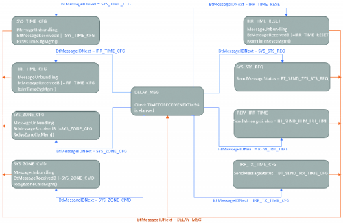
Fig. 5
Each message received, provides a dedicated function that processes the information, as described below:
- the beginning of the processing of a message is determined by the fact that the identifier of the message is set in the BtMessageReceivedB bit mask, for example BtMessageReceivedB | = SYS_TIME_CFG.
- The end of the processing of a message is determined by the fact that the identifier of the message is reset in the BtMessageReceivedB bit mask and the reception phase can be considered completed, for example BtMessage
ReceivedB &= ~SYS_TIME_CFG.
In Listing 3 we propose part of the implemented code for receiving the SYS_TIME_CFG message. Listing 4 contains the code for the RxSysTimeCfgMgm function.
Listing 3
case SYS_TIME_CFG :
BtMessageMatrix[SYS_TIME_CFG_IDX].id = BtMessageID;
BtMessageMatrix[SYS_TIME_CFG_IDX].bytenumber = Lenght;
for(MessageBufferIdx = 0; MessageBufferIdx < BtMessageMatrix[SYS_TIME_CFG_IDX].bytenumber;
MessageBufferIdx++)
{
BtMessageMatrix[SYS_TIME_CFG_IDX].buffer[MessageBufferIdx] =
BtMessageReceived[MessageBufferIdx + 1];
}
BtMessageReceivedB |= SYS_TIME_CFG;
BtMessageID = DELAY_MSG;
BtMessageIDNext = DELAY_MSG;
RxSysTimeCfgMgm();
break;
For sending messages, the BtTransmitMessages() function has been implemented. The transmission of messages, managed by the status machine visible in Fig. 6, is decided from time to time by the various managers or the App, which may require the transmission of a particular message.

Fig. 6
The messages to be transmitted are first packaged in the BtMessageMatrix by a dedicated function, at this point the BtMessageTransmittedB flag is set indicating that the message is ready to be transmitted, then the BtMessageToSend buffer is composed and sent by calling the MdmBt_SendBtMsg API, MAX_TRANSM_BUFFER_LEN). Finally, the BtMessageTransmittedB flag is reset to indicate that the transmission has ended.
Listing 4
if((BtMessageReceivedB & SYS_TIME_CFG) != 0)
{
ConfigSystime.days = BtMessageMatrix[SYS_TIME_CFG_IDX].buffer[BYTE_0];
ConfigSystime.hours = BtMessageMatrix[SYS_TIME_CFG_IDX].buffer[BYTE_1];
ConfigSystime.minutes = BtMessageMatrix[SYS_TIME_CFG_IDX].buffer[BYTE_2];
ConfigSystime.seconds = BtMessageMatrix[SYS_TIME_CFG_IDX].buffer[BYTE_3];
CfgSysTimeEn = TRUE; //abilito la configurazione
BtMessageReceivedB &= ~SYS_TIME_CFG;
}
In Listing 5 you will find the code implemented to send the message BT_SEND_SYS_REQ.
IrrigationMgr
It consists of an EvMgmStatusV state machine which, at the first start, goes into the INIT state where an additional InitMgm state machine resets all programming to default values, and then goes to the initialisation state of the solenoid valves in order to switch them off if they are still on.
Once the initialization phase is over, EvMgmStatusV goes to the EV_IDLE state where it checks minute by minute if there are irrigations to be scheduled in automatic mode and checks if there are solenoid valves to be controlled in manual mode.
Observing the block diagram in Fig. 7, when an automatic irrigation is started, EvMgmStatusV starting from the state EV_IDLE, goes to the state EV_RUN_AUTO_MODE and remains there until the scheduling is finished or until a manual activation is required, in the latter case it goes to the state EV_RUN_MANUAL_MODE.
At the end of an automatic irrigation phase, the solenoid valve is turned off and the valve returns to the EV_IDLE state.
Listing 5
case BT_SEND_SYS_STS_REQ :
TxSysStsReqMgm();
if((BtMessageTransmittedB & SYS_STS_REQ) != 0)
{
SendMessagePreamble = 0;
BtMessageToSend[SendMessagePreamble++] = BtMessageMatrix[SYS_STS_REQ_IDX].id;
for(MessageBufferIdx = SendMessagePreamble; MessageBufferIdx < MAX_TRANSM_BUFFER_LEN;
MessageBufferIdx++)
{
if(MessageBufferIdx < BtMessageMatrix[SYS_STS_REQ_IDX].bytenumber)
{
BtMessageToSend[MessageBufferIdx] = BtMessageMatrix[SYS_STS_REQ_IDX].
buffer[MessageBufferIdx - SendMessagePreamble];
}
else
{
BtMessageToSend[MessageBufferIdx] = 0;
}
}
MdmBt_SendBtMsg (BtMessageToSend, MAX_TRANSM_BUFFER_LEN);
BtMessageTransmittedB &= ~SYS_STS_REQ;
}
SendMessageStatus = BT_SEND_DELAY;
SendMessageNextStatus = BT_SEND_DELAY;
break;
qui invece la funzione TxSysStsReqMgm:
void TxSysStsReqMgm(void)
{
uint8_t ZoneIdx;
BtMessageMatrix[SYS_STS_REQ_IDX].id = SYS_STS_REQ;
BtMessageMatrix[SYS_STS_REQ_IDX].bytenumber = SYS_STS_REQ_BYTE_LEN;
BtMessageMatrix[SYS_STS_REQ_IDX].period = SYS_STS_REQ_PRD;
BtMessageMatrix[SYS_STS_REQ_IDX].type = BT_MESSAGE_TX;
BtMessageMatrix[SYS_STS_REQ_IDX].buffer[BYTE_0] = 0;
BtMessageMatrix[SYS_STS_REQ_IDX].buffer[BYTE_1] = 0;
BtMessageMatrix[SYS_STS_REQ_IDX].buffer[BYTE_2] = 0;
for(ZoneIdx = 0; ZoneIdx < MAX_NUM_ELECTROVALVES; ZoneIdx++)
{
BtMessageMatrix[SYS_STS_REQ_IDX].buffer[BYTE_0] |= IrrigationEv[ZoneIdx].config << ZoneIdx;
BtMessageMatrix[SYS_STS_REQ_IDX].buffer[BYTE_1] |= ((IrrigationEv[ZoneIdx].activationstatus ||
EvCmdAutoMode[ZoneIdx]) << ZoneIdx);
BtMessageMatrix[SYS_STS_REQ_IDX].buffer[BYTE_2] |= (IrrigationEv[ZoneIdx].activationstatus);
}
BtMessageTransmittedB |= SYS_STS_REQ;
}
When IrrigationMgr is in the EV_RUN_MANUAL_MODE state, manual irrigation is in progress. For safety reasons, if manual irrigation is not stopped by the user through the App, it is automatically stopped by the software after a 5 minute timeout. Once the manual irrigation is finished, it returns to the EV_IDLE state.

Fig. 7
The solenoid valves are operated via the API I2cSlv_SendI2cMsg(I2cTxBuffer, HSD_MODULE_I2C_ADDRESS, 2) , where:
- I2cTxBuffer is a buffer that contains the drive command of the HSDs on the SB140, it consists of two elements:
1) by the on/off command 0x50
2) a bit mask indicating which solenoid valve should be switched on/off, for example:
by sending mask 0101 we ask to switch on solenoid valves 1 and 3 and switch off the remaining ones (solenoid valves 2 and 4), while with mask 0001 we ask to switch on solenoid valve 1 and switch off the remaining ones (solenoid valves 2,3 and 4);
- HSD_MODULE_I2C_ADDRESS indicates the 0x01 address we have set on the DipSwitch on the SB140;
- 2 is the buffer size that we want to transmit on the I²C bus.
SystemTimeConfigMgr
When the App connects via Bluetooth to the Mercury system, it sends the information related to the current day, hour, minutes and seconds and the SystemTimeConfigMgr takes care of setting the RTCC Hardware through an api, Rtcm_SetRtccDate, that the framework makes available to us, which receives an input structure that will contain all the information.
SystemTimeMgr
Set all information to 0 in the RTCC_INIT phase to pass through the RTCC_RUNNING state in which the time will start.
Once the BT connection with the App is made, SystemTimeMgr counts the time starting from the current time communicated to it.
LcdMgr
Now let’s move on to the last Manager, the one that shows on the LCD display of the Expansion Board two pieces of information, which are the name of the system “IrrigationSystem” on the first line, while on the second line, day, hour, minutes and seconds.
Initially the LcdStatus state machine (described by the block diagram proposed in Fig. 8) is in the LCD_INIT state let’s switch on the display: using the API I2cSlv_SendI2cMsg we send the command LCD_BACKLIGHT_CMD = 0x52 which tells us that we want to switch on or off the backlight of the display and the parameter LCD_BACKLIGHT_ ON = 0x01 to indicate that we want to switch on.

Fig. 8
The address to use in this case is the one set on the EB210 DipSwitch, LCD_MODULE_I2C_ADDRESS = 0x02
At this point LcdStatus goes to the Clear state where using the command LCD_CLEAR_CMD = 0x53, the display lines are reset. At this point we go to the LCD_WRITE_LINE1 state where we select line 1 LCD_SELECT_LINE_1 = 0x54 to write on the display “IrrigationSystem”, in this case the command to write a line on the display will be LCD_WRITE_CMD = 0x51. So we go to LCD_WRITE_LINE2 state where we will select line 2 LCD_SELECT_LINE_2 = 0x55 and update the time if this is different from the one previously written.
Conclusions
In the two articles dedicated to the irrigation control unit based on Mercury System we showed you how, in a very simple way, we were able to write the firmware of our Base Board BB110 without having to manage the microcontroller configurations or having to implement specific drivers for the chosen communication buses. The APIs provided by the Mercury framework make development very easy.
I made the user interface, in Java with Android Studio, but I could have used any other tool, in fact, once determined the message map, the user interface can be created in the way we prefer: nothing prevents us to create a web interface, use PyQT or software on PC in visual basic or the system/language we prefer. At this point our Irrigation System based on the Mercury system has been fully described and programmed, so when you finish it will be working.
We conclude the series of articles reporting that on our website together with the various files of the article are available for download the message map, the binaries and the source codes of the software (firmware and app) to use or modify, in order to realize and customize your irrigation system.
From openstore
Mercury System BB110 – Base Board Model A
Modem Board MB310 – Bluetooth for Mercury system
Mercury System SB140 – HSD Slave Board
Mercury System EB210 – LCD 16×2 Expansion Board
Mercury System PB110 – Power Board
