
As the hot season comes closer, the problem of watering the lawn in the garden or the plants on the balcony or terrace arises again. For the management of small and medium systems, there are many commercial solutions, but these are often systems that have been in use for years, which are struggling to adapt to new standards, especially those related to connectivity and IoT. Being able to manage the irrigation system using a smartphone with an app is certainly a more modern and more practical solution than using the classic interfaces of embedded systems, often minimal and difficult to use.
In these pages we would like to suggest an irrigation control unit managed by smartphone or tablet via Bluetooth, which we have chosen to implement with the Mercury System hardware described in a previous article; the choice fell on this because it relies on a software development system that greatly facilitates the development of applications related to connectivity and IoT.
Traditional electronic irrigation systems are usually without connectivity, are installed on a wall and the only user interface they are equipped with is an LCD display plus a series of buttons; their configuration and programming require the physical presence of a person. It is therefore clear that with traditional systems the only way to verify that the programmed irrigations are performed is physically in the vicinity of the controller or sprinklers.
Instead, a system based on smartphones and apps allows you to manage irrigation in a simpler and more intuitive way, so it is within everyone’s reach and can be managed remotely.
Block diagram
Fig. 1 shows the block diagram of the system we suggest you to realize: as you can see, we used a BB110 as a logic unit, connected to an SB140 (HSD 4 channels) for the management of the solenoid valves (up to a maximum of four), all connected through an EB210 (LCD expansion board), which is the connection element between BB110 and SB140 (the EB210 has two Mercury standard sockets) and also adds an LCD display. BT connectivity is provided by an MB310, while we used a PB110 to power the whole system.
Let’s take a closer look at the various components of the system.

Fig. 1
Base Board BB110
An irrigation system needs a mind that manages irrigation according to specific criteria, it must provide the user with the ability to manually control irrigation, but mainly program them so that they run automatically, in fact, the BB110 aims to communicate with all slaves using the I²C Bus (except for modems that use a dedicated bus), this type of bus greatly simplifies the hardware architecture by reducing the number of connection lines between the various devices. In the Base Board we will implement the software that represents all the operating logic of our system. As explained in the previous articles, it is the only Board that needs to be programmed just to provide the system with “intelligence”.
The BB110 board (Fig. 2) has three connectors relating to the power supply:
- Micro USB connector, system primary power supply
- JST connector to which the lipo will be connected, this connector is part of a battery charging circuit, so if we power through the micro USB connector and connect the lipo, the lipo will charge, otherwise in the absence of power, the lipo will power Mercury.
- The power pins next to the micro USB connector are used to power the BB110 when we have only the power cable available to power the system.
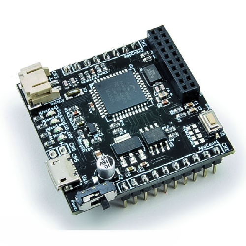
Fig. 2
Modem Board MB310
We are going to switch the system to a Bluetooth modem (Fig. 3), to be connected directly to the BB110, to give the user the possibility to interface with the system and interact with it by sending commands in order to have information about the system status. The Bluetooth module is contained on the MB310 Modem Board. The board provides Bluetooth connectivity to the system and interfaces to the system with a dedicated serial line (UART). The core of the MB310 is the HC-05 Bluetooth module which connects to the BB110 through a dedicated connector, the Mercury Modem connector (shown in Fig. 4), through which it receives power and access to the communication bus. The fact of having a dedicated connector (since the communication bus with the Base Board is the UART) makes this module different from the other slaves because here it is not necessary to configure any I²C address. In Fig. 5 you can see the block diagram of the MB310.

Fig. 3
Through a message map, it will be possible to manage the exchange of information between the Smartphone and Irrigation System. The modem will allow us, using an Android smartphone, the communication with the baseboard that through the slave board High Side Driver allows us to implement the solenoid valves (maximum 4). As mentioned earlier, we chose the Bluetooth modem as the type of connectivity, but we could have chosen to use a WiFi modem as well.

Fig. 4
If we think about it, an irrigation system is a slow system, it doesn’t need a high-frequency message exchange, you don’t need to do pushed controls, you don’t need to connect to the irrigation system via the Internet.

Fig. 5
High Side Driver Slave Board SB140
It is a slave unit that will give us the possibility to operate the solenoid valves to turn them on and off if necessary; the slave is equipped with four High Side Drivers (Fig. 6) that allow us to operate devices and power them by connecting the appropriate power source to the pins on the screw terminal block. The dip-switch on the SB140 allows us to configure its I²C address.

Fig. 6
The SB140 slave, High Side Driver (HSD), is very useful in those cases where you have to make ON/OFF actuations, so you can think of the SB140 as a set of four switches that work in DC and give power to the devices connected to it. This Board is also equipped with logic, in fact it is able to receive I²C commands to turn on or off the HSD present. Each of the four HSDs is associated with an LED that lights up whenever its HSD is controlled and remains off when it is not controlled. Each HSD is capable of switching currents up to 1A.

Fig. 7 shows the top view of the screw terminal block on the board through which the loads can be connected.
Looking at the block diagram in Fig. 8, we see the microcontroller that allows the board to have its own logic, in fact it connects to the BB through the Mercury Standard connector and through the four-channel dip-switch it is possible to set an I²C address, the bus used for data transmission. Remember that the slaves do not require programming: the software on board already implements the necessary logic and is fully integrated with the Mercury Framework. Through the programming connector it is possible to update the board software.

Fig. 8
From the block diagram shown, we can see that this slave consists of a PIC16F1829 microcontroller, the Mercury Connector (which is the standard connection for stacking the various modules), a four-way dip-switch, a service LED and four HSD to which as many LEDs are connected.
Expansion Board EB210
The expansion board will give us the possibility to position the boards described above in a planar way. The EB210 is also equipped with a display and gives the possibility to connect with other slaves. Through a dip-switch, it is possible to configure an I²C address to communicate the strings to be shown on the display. With the EB210 (Fig. 9) the Irrigation System will show us some information on the display: system name, day, hour, minutes and seconds.
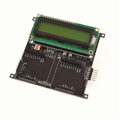
Fig. 9
The main function of the Expansion Boards is to allow the various boards to be arranged planarly. The EB210 implements two features: it offers a user interface through the 16×2 LCD display and mounts two standard Mercury connectors to connect the boards you want to expand the system with. The block diagram in Fig. 10 shows that the core of the system is the PIC16F1829, to which is connected a 16×2 display, a service LED and a 4-channel dip-switch with which you can configure the I²C address, a service LED and the potentiometer for contrast adjustment.

Fig. 10
As mentioned before, there are also the two standard Mercury connectors and the reprogramming connectors:
- near the LCD, in case we need to update the slave software;
- near Mercury Connector #2, in case we need to reprogram the slave we connect.
If you want to further expand the system, there is an I²C Connector that allows us to connect another expansion board.
Power Board PB110
This board allows us to power both the Mercury System and the solenoid valves we intend to mount with a power supply. The Base Board and the solenoid valves use different power supplies, the Power Board gives us the possibility not only to provide a double power supply, but also to meet the power requirements related to the introduction of the solenoid valves, in fact, it allows us to power at 5V the Base Board and the slaves connected and to supply the 12V and the necessary current to the solenoid valves. When the PB110 is powered by the 12V dc power supply, through the special charging circuit on the Base Board, the LiPo battery is recharged.
Elettrovalvole 12Vcc
Irrigation System, for how the system has been configured, will support up to a maximum of four solenoid valves, normally closed, powered at 12V cc. The solenoid valves are of the type shown in Fig. 13, which shows an electrically assembled system.

Fig. 11
Lipo battery 3.7V
This battery is used as a backup power supply in case of power failure while continuing to power the system. With a 4,400m Ah LiPo, Mercury can operate autonomously for several days; in fact, as can be deduced from the datasheet, the Mercury based irrigation system consumes relatively little power.
12VDC Power supply
The DC solenoid valves available on the market are usually powered at 12V, so for the system we need a power supply capable of delivering this voltage. The current of the power supply must take into account the fact that it could be activated more than one at a time, although normally in irrigation systems with “mushroom-shaped” regulators, in order to have the necessary pressure to open the regulators, this option is not recommended; in fact, these regulators (unlike dispersing pipes or simple jets) have the jet that comes out under the effect of pressure and being opposed by a spring, when there are several, the water pressure must be such as to overcome the force of the contrast spring. This is why we decided to operate only one solenoid valve at a time.
Therefore, in principle you need a power supply unit capable of delivering at least 600 mA, also because, for the above reasons, unless you make changes to the code we will never see all the solenoid valves working together.
In principle, the system in its complete state is presented as in Fig. 12;
where there are the four solenoid valves, the Mercury system, the smartphone and the virtual block Connectivity which is only the method chosen to communicate with Mercury. In this case the Connectivity block is represented by a Bluetooth connection, in fact an MB310 is used as modem card.
To manage the system, a special Android App has also been created to be installed on the smartphone, which represents nothing more than the user interface of the system. We will deal with the description of the app, the SW and the operation of the system in the next episode.

Fig. 12
System requirements
Let us take a look at the constraints that need to be considered in the implementation of our system.
The PB110 can deliver up to 1.5A, so it would be able to supply more than one solenoid valve at the same time (each solenoid valve absorbs about 300 mA), but, as already mentioned, you have to consider the hydraulic pressure constraints for civil homes 1.5 bar – 3 bar, which is usually sufficient to irrigate one area at a time.
To make sure that sufficient hydraulic pressure arrives at the irrigation solenoid valves, the system is prepared (through the software) to pilot one solenoid valve at a time, although nothing physically prevents us from operating more than one sprinkler at a time. Therefore, although the system has up to four solenoid valves, it will not absorb the current of all four because it activates only one at a time.
While the PB110 provides us with the voltages and currents needed to power the whole, the SB140, the High Side Driver board, offers us the possibility to implement the solenoid valves through the commands given by the base board. The SB140, having at its disposal four High Side Drivers, can drive up to four solenoid valves (in our case one at a time), this slave board receives the commands from the Base Board and implements what is requested. The Base Board controls the SB140 and, therefore, the solenoid valves according to the programs that have been stored or commands them because through the App, from our Android smartphone, we are manually asking to start an irrigation. The SB140 receives ON/OFF commands for each single solenoid valve.
Every time a solenoid valve is activated, the corresponding LED lights up, thus giving us evidence that we are actually driving the solenoid valve.
The solenoid valves we have chosen to use are monostable type, normally closed and powered at 12V dc, the choice of DC solenoid valves greatly simplifies our hardware, we do not have to worry about introducing alternating elements in our system, thus also increasing the level of safety. We could have chosen to use bistable solenoid valves, but although these consume much less, (they only draw current during switching) and can be battery powered (they are usually powered at 9V), they have one drawback:
if they should be blocked/damaged or if for some reason they should no longer be powered, they would remain in the last state implemented, if a bistable solenoid valve remains blocked in the open state, we would not have the possibility to stop the water flow if not acting manually on our hydraulic system.

Fig. 13
Conclusions
In the next episode we will describe the realization of the Firmware and Android App designed to manage the system remotely.
In particular, we will see how through the App you can configure the programming and manually operate the solenoid valves, the App also gives you the ability to monitor the current status of the system and view all the configured programs or configure new ones.
The firmware, on the other hand, implements all the logic of the system and actually takes care of storing the programming, scheduling it, implementing it, reading the status of the solenoid valves, managing time.
It will also show the management of Bluetooth messages between App and Firmware.
From openstore
Mercury System BB110 – Base Board Model A
Modem Board MB310 – Bluetooth for Mercury system
Mercury System SB140 – HSD Slave Board
Mercury System EB210 – LCD 16×2 Expansion Board
Mercury System PB110 – Power Board
