
Electricity costs are rising, and just in case this is not enough, if you exaggerate with consumption your house circuit often stops working in the very moment of your greatest need. This project allows you to keep an eye on your electricity instant consumption even remotely.
[iframe_loader src=”http://emoncms.org/boris&id=2505 ” ]
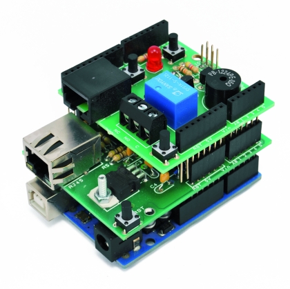
The acquisition of current consumption rates takes place by means of small clamps placed on top of the phase conductor of the power line section you want to control. The acquisition system is based on a commercial product available in our store, the FR491. The kit includes a meter clamp to measure current plus a data transmission unit. The transmission occurs at 433.92 MHz and can cover about thirty meters. The central unit gathers samples sent via radio by the peripheral devices and stores them and shows a series of information about consumption, usage bursts and relative costs, by means of a nice web page.

The central unit is also equipped with an RJ45 output that allows you to connect it to a PC via a TTL-USB converter. Our goal is to connect the central unit to an Arduino Uno (instead of a PC), and implement a web enabled monitoring system. To do this we bypass the TTL-USB converter and connect the output of the controller directly to the D6 (RX) and D7 (TX) pins on the Arduino. The Arduino board mounts two shield. The Ethernet shield allows you to do both: sending data to the emoncms remote service for collection, storage and presentation, and respond directly to web calls used to monitor the status of sensors and alarms and manage the thresholds under which the alarm is started.
The shield must be connected via the Ethernet connector to a network that allows access to the internet. The second shield is the local monitoring and alarm management unit and the wiring diagram is visible in the section. The shield has a relay output and a buzzer, triggered if the consumption exceeds the threshold set via the web page. It also sports two buttons (besides the reset button) that can be activated to pausea the alarm function. The software sketch is made so that the alarm is still reactivated as soon as the consumption goes back below the threshold that caused the trip. A LED indicates the general operational state of the system.
From the embedded web page you can activate and deactivate the alarm, pause it and set the alarm new threshold: upon alarm activation, buzzer plays a melody .
Regarding emoncms, obviously you cannot install the server on Arduino, we will use the functionality available from emoncms website itself, integrating them with the available page from Arduino web server.
Diagram of the shield

The shield is powered thanks to Arduino’s 12 V: used to power the relay coil and the buzzer.
But, let’s analyze the serial line coming from the FR491 central controller. The output signal taken from line 8 of the RJ45 connector is connected to pin D6 (RX) of Arduino while the input signal on line 7 of the RJ45 connector is connected to pin D7 (TX) of Arduino. To use Arduino’s D6 and D7 pins for serial communication your need, in the sketch, to call the SoftSerial library.
The threshold breaking alarm activation outputs are at D4 pin for the relay driven by the switching transistor T1 and at D5 for what regards the buzzer, which is also driven by the switching transistor T2. Pin D3 drives LD1.
On FT1046 shield two additional buttons P1, connected to pin D9, to activate and deactivate the alarm locally and P2, connected to pin D8, to pause the alarm function.


The sketch for Arduino
#include <EtherCard.h>
#include <SoftwareSerial.h>
#include <EEPROM.h>

#define DEBUG 1               // set to 1 to display debug info via seral link

int ledalarm = 3;               // pin the LED is on   (you can't use the onboard one as the ethernet card uses it)
int pulsalarm = 9;
int pulspause = 8;
int alarmout = 4;
int speakerPin = 5;

char TextBox1[10];            // Data in text box

int length = 15; // the number of notes
char notes[] = "ccggaagffeeddc "; // a space represents a rest
int beats[] = { 1, 1, 1, 1, 1, 1, 2, 1, 1, 1, 1, 1, 1, 2, 4 };
int tempo = 300;
boolean alarm=0;

#define APIKEY  "**************"
#define emonlink "http://emoncms.org/boris&id=2505"

// ethernet interface mac address
static byte mymac[] = { 0x74,0x69,0x69,0x2D,0x30,0x31 };
// ethernet interface ip address
static byte myip[] = { 192,168,0,99 };
// gateway ip address
static byte gwip[] = { 192,168,0,1 };

static const byte dnsip[] = { 192,168,0,1 };

char website[] PROGMEM = "emoncms.org";
static const byte hisip[] = { 213,138,101,177 };

unsigned long previousMillis_power=0;
int power_postrate=10000;   //post every 10s
int watts=0;
int maxwatts=3000;
byte inData1[10]; // Allocate some space for the string
byte inData2[10];
//byte inData3[10];

boolean pause=0;

char str[20];

SoftwareSerial mySerial(6, 7); // RX, TX

// web page buffer
  byte Ethernet::buffer[800];
  BufferFiller bfill;

// store html header in flash to save memory
char htmlHeader[] PROGMEM =
      "<html><head><title>Power meter by Boris</title></head><body>"
      "<h2 style='text-align: center;'><em><span style='color: rgb(153, 0, 0);'>Power meter by Boris</span></em></h2>"
;

// ----------------------------------------------

// HTML page to display

static word homePage() {
    checkmcee();
    bfill = ether.tcpOffset();

    // read A0 status
    //word sensorValue = analogRead(sensorPin);

    maxwatts =  EEPROM_readint(0);
    Serial.print("maxwatts in mem : ");
    Serial.println(maxwatts);

    Serial.print("alarm in mem : ");
    Serial.println(EEPROM_readint(5));

    // read statues of the LED
    char* alarmstat;
    if ( EEPROM_readint(5) == 1 ) {
      alarmstat = "On" ; }
    else {
      alarmstat = "Off"; }

    bfill.emit_p( PSTR (
      "$F<p>"    // $F = htmlheader in flash memory
      "<center>"
      "<iframe src='$S' width='1000' height='500' frameborder='0' ></iframe><br/>"
      "<em>Alarm: $S <br/>"
      "Alarm threshold: $D <br/>"
      "</em></p><p>"
      "<A HREF='?cmd=on'>Alarm on</A><br/><br/>"
      "<A HREF='?cmd=off'>Alarm off</A><br/><br/><br/>"
      "<A HREF='?cmd=pause'>Alarm pause</A><br/><br/>"
      "<FORM>Insert alarm threshold <input type=text name=maxwatts size=4 value=$D> <input type=submit value=Enter> </form> <br/><br/>"
      "<A HREF='http://www.open-electronics.org'>More info</A>"
      "</p></center></body></html>"
    ) , htmlHeader , emonlink, alarmstat , maxwatts , maxwatts ) ;

    return bfill.position();

  }

// ----------------------------------------------

void setup () {

  pinMode(ledalarm, OUTPUT);
  pinMode(alarmout, OUTPUT);
  pinMode(speakerPin, OUTPUT);
  pinMode(pulsalarm, INPUT);
  digitalWrite(pulsalarm, HIGH);
  pinMode(pulspause, INPUT);
  digitalWrite(pulspause, HIGH);

  Serial.begin(9600);
  Serial.println("\n[webClient]");

  if ((EEPROM.read(10)!=10)){
    Serial.println("First power on");
    EEPROM.write(10, 10);
    EEPROM_writeint(0, maxwatts);
    alarmoff();
  }
  else
  {
    Serial.println("Data on eeprom already stored");
  }

    maxwatts =  EEPROM_readint(0);
    Serial.print("maxwatts in mem : ");
    Serial.println(maxwatts);

    Serial.print("alarm in mem : ");
    Serial.println(EEPROM_readint(5));
    if (EEPROM_readint(5)==1){
      digitalWrite(ledalarm, HIGH);
    }

  if (!ether.begin(sizeof Ethernet::buffer, mymac,10))
    Serial.println( "Failed to access Ethernet controller");
 else
   Serial.println("Ethernet controller initialized");

  ether.staticSetup(myip,gwip,dnsip);
  ether.copyIp(ether.hisip, hisip);

  ether.printIp("IP Address:\t", ether.myip);
  ether.printIp("Netmask:\t", ether.mymask);
  ether.printIp("Gateway:\t", ether.gwip);
  ether.printIp("DNS:\t", ether.dnsip);
  ether.printIp("SRV: ", ether.hisip);

  mySerial.begin(9600);

}

// ----------------------------------------------

void loop () {

  word len = ether.packetReceive();
  word pos = ether.packetLoop(len);
  if(pos) {
        Serial.print("pos ");
        Serial.println(pos);
        printpage(pos);
  }

if ((millis()%1000)==0){
  Serial.println(millis());
  delay(50);
    if (pause==1)
    {
      digitalWrite(ledalarm, HIGH);
      delay(200);
      digitalWrite(ledalarm, LOW);
      delay(200);
    }
    else
    {
      if (alarm=1)
      {
        digitalWrite(ledalarm, HIGH);
      }
      else
      {
        digitalWrite(ledalarm, LOW);
      }
    }
}

if ((millis() - previousMillis_power) > (power_postrate) )
  {
    previousMillis_power=millis();

    checkmcee();

    Serial.print("watts ");
    Serial.println (watts,DEC);

    pubblica();
    checkalarm();

  }

  if (digitalRead(pulsalarm)==0){  //toggle alarm

    if (EEPROM_readint(5)==1) {
      alarmoff();
      delay(500);
    }
    else
    {
      alarmon();
      delay(500);
    }
  }

  if (digitalRead(pulspause)==0){  //toggle alarm
    pause=1;
    Serial.println("pause on");
  }

}

void alarmon(){
  digitalWrite(ledalarm, HIGH);   // set the LED on
  EEPROM_writeint(5, 1);   //alarm off
  Serial.println("alarm on");
  alarm=1;
}

void alarmoff(){
  digitalWrite(ledalarm, LOW);   // set the LED on
  EEPROM_writeint(5, 0);   //alarm off
  Serial.println("alarm off");
  alarm=0;
}

void printpage(word pos){

        char* bufferdata = (char *) Ethernet::buffer + pos;

         Serial.println("----------------");
         Serial.println("data received:");
         Serial.println(bufferdata);
         Serial.println("----------------");

       // "on" command received
       if (strncmp( "GET /?cmd=on" , bufferdata , 12 ) == 0) {
           alarmon();
       }

       // "off" command received
       if (strncmp( "GET /?cmd=off" , bufferdata , 13 ) == 0) {
           alarmoff();
       }

       // "pause" command received
       if (strncmp( "GET /?cmd=pause" , bufferdata , 13 ) == 0) {
           //digitalWrite(LEDpin, LOW);   // set the LED on
           Serial.println("pause received");
           pause=1;
       }

       // read data from text box
       if (strncmp( "GET /?maxwatts=" , bufferdata , 11 ) == 0) {
           Serial.print ( "text box input received - " );
           if (ether.findKeyVal(bufferdata + 6, TextBox1 , sizeof TextBox1 , "maxwatts") > 0) {

             Serial.print ( "input = " );
             Serial.println ( TextBox1 );
             EEPROM_writeint(0, atoi(TextBox1));

           }
       }

      ether.httpServerReply(homePage()); // send web page data

}

void checkmcee(){
    Serial.println("checkmcee ");
    int data=0;
    int index=0;
    mySerial.write((byte)0xAA);
    mySerial.write((byte)0x02);
    mySerial.write((byte)0x00);
    mySerial.write((byte)0xAD);
    delay(500);
    while (mySerial.available() > 0) {
      byte inByte = mySerial.read();
      //Serial.write(inByte);
      if (inByte=='S'){
        index=0;
        data++;
      }

      switch (data){
       case 1:
         inData1[index] = inByte; // Store it
         index++;
         break;
       case 2:
         inData2[index] = inByte; // Store it
         index++;
         break;
      }

    }

    watts=0;
    watts=(inData2[6]<<8) + inData2[5];

}

void pubblica()
{
    str[0]='\0';
    srtJSON(str);                                   //Start JSON
    addJSON(str,"realP",watts);                   //JSON line 1 - add more lines as needed
    endJSON(str);
    Serial.println(str);
    Serial.println(strlen(str));

    ether.browseUrl(PSTR("/api/post?apikey="APIKEY"&json="), str, website, my_result_cb);

}

void checkalarm(){

if (alarm=1){
  if (watts>maxwatts){
    if (pause==0){
      if (EEPROM_readint(5)==1)    //if alarm on
      {
          digitalWrite(alarmout, HIGH);
          play();
      }
    }
  }
  else{
    pause=0;
    digitalWrite(alarmout, LOW);
  }
}
}

// called when the client request is complete
static void my_result_cb (byte status, word off, word len) {
  Serial.print("<<< reply ");
  //Serial.print(millis() - timer);
  //Serial.println(" ms");
  Serial.println((const char*) Ethernet::buffer + off);
}

//write word to EEPROM
void EEPROM_writeint(int address, int value) {
  EEPROM.write(address,highByte(value));
  EEPROM.write(address+1 ,lowByte(value));
}

unsigned int EEPROM_readint(int address) {
  unsigned int word = word(EEPROM.read(address), EEPROM.read(address+1));
  return word;
}

void playTone(int tone, int duration) {
  for (long i = 0; i < duration * 1000L; i += tone * 2) {
    digitalWrite(speakerPin, HIGH);
    delayMicroseconds(tone);
    digitalWrite(speakerPin, LOW);
    delayMicroseconds(tone);
  }
}

void playNote(char note, int duration) {
  char names[] = { 'c', 'd', 'e', 'f', 'g', 'a', 'b', 'C' };
  int tones[] = { 1915, 1700, 1519, 1432, 1275, 1136, 1014, 956 };

  // play the tone corresponding to the note name
  for (int i = 0; i < 8; i++) {
    if (names[i] == note) {
      playTone(tones[i], duration);
    }
  }
}

void play(){
  for (int i = 0; i < length; i++) {
    if (notes[i] == ' ') {
      delay(beats[i] * tempo); // rest
    } else {
      playNote(notes[i], beats[i] * tempo);
    }

    // pause between notes
    delay(tempo / 2);
    if ((digitalRead(pulsalarm)==0)||(digitalRead(pulspause)==0)){
      break;
    }
  }
}
At the beginning of the sketch we can find all the variables definition needed talk with the emoncms server, and those related to the Ethernet interface configuration, in this case you have to set the MAC address of your Ethernet shield (usually specified on a special label affixed on the shield itself) and a static IP address compatible with the addressing scheme of your home network.
// ethernet interface mac address
static byte mymac[] = { 0x74,0x69,0x69,0x2D,0x30,0x31 };
// ethernet interface ip address
static byte myip[] = { 192,168,0,99 };
// gateway ip address
static byte gwip[] = { 192,168,0,1 };
static const byte dnsip[] = { 192,168,0,1 };
The Setup block configures the Arduino pin for alarm management and initializes the debug serial port. In case of the first system start, EEPROM gets valued 3000, as the threshold value for triggering an alarm. Furthermore, setup configures the Ethernet port and initializes the serial port for the communication with the FR491 control unit.
The loop block is the one that runs in a continuous loop. The first action is to listen for external HTTP requests, intercept and handle them according to the “actions” received.
The statements checking for external http requests are:
word len = ether.packetReceive();
word pos = ether.packetLoop(len);
Calling the Arduino Board IP address from an external browser you only receive a basic emoncms display. In the page you’ll find the links and the text fields to set the alarm threshold, enable, disable, and pause the alarm.
If there are no requests, at each interval – as set in the power_postrate variable (three seconds) – the reading of the measurements is performed and stored in the FR491 control unit, using the checkmcee() function.
To query the FR491 you need to send the following commands:
mySerial.write((byte)0xAA);
mySerial.write((byte)0x02);
mySerial.write((byte)0x00);
mySerial.write((byte)0xAD);
Doing this, the FR491 will respond with the total consumption.
The FR491 control unit responds by sending a string as per the following example:
S01\0xff\0xff\0x00\0x002
S02\0xb73\0x00\0x002
……
S16\0xff\0xff\0x00\0x002\0xf3
The sample regarding the consumption of the sensor we’re interest in, is in positions 5 and 6 (after the “S”) of the S02 string, with the least significant byte (5) first and the most significant (6) following. You can convert it with:
watts=(inData2[6]<<8) + inData2[5];
Once the data is acquired, is then published on the emoncms server, with the pubblica() method, using an http call based on JSON Protocol.
Finally checkalarm() checks if the value exceeds the alarm threshold or not. If so the relay connected to Arduino’s D4 pin is activated. Depending on the setup (alarm is activated, pause is activated) the buzzer on D5 gets activated as well.
Also in loop() the P1 and P2 buttons states are checked to see if the activation or deactivation of the alarm (P1), or pause (P2), were requested. In case P1 button is clicked, it activates the same functions activated via the web page the commands: alarmon(), alarmoff (). If you click P2 the value of the pause variable is brought to “1” to control the operation of checkalarm() (LD1 blinks in case the alarm is activated).
Also from the webpage you’ve access to a text field to set the threshold, in Watts, for alarm activation and the Enter button (handled in printpage()).
The body of the web page is composed and sent by the function homepage() invoked by the statement:
ether.httpServerReply(homePage());
While composing the page an “iframe” contains the graphics to display the consumption data produced by the emoncms server.
Before using the whole system you need to configure the emoncms server. To configure the server follow the steps below.

Emoncms Server Configuration
The first thing to do is to create an account on emoncms at http://emoncms.org/user/login.
After registering go to the Input panel and click on the top right link, “Input API Help”. This will open a page where there are two long data strings: the API keys for reading and writing. We will use the writing Apikey as an authentication key inside the JSON message sent by the program that runs on ARDUINO.
First thing to do now, is to add to the program sketch the following define:
#define APIKEY “**************” (your api key)
For now, just copy the APIKEY of our configuration by replacing the one in the sketch.
Compile the code and upload it to the Arduino. With everything connected make it run few minutes.
Go back to open the Input panel, that should be empty now. Expand clicking on “+” and, as see the name of your input, “realP”, in the page.
Emoncms Inputs only create room for real values: kind of a port that is assigned to each channel. To create the containers where data is stored you need to create Feeds. We do this from the Input page. Double click on the blue name of the “realP” input and open the Feed creation page, give the feed a name, for example the same name ” realP” and press ADD.
Go back to the feed page and click the “+” to expand.
Now we can move on to the page graphics composition, doing it by selecting Dashboard, which introduces us to a page where the graphic pages are referred (you’ ll see “No dashboards created”).
To create our dashboard click on the small round little button at the top right with the “+”. You’ll see a line that indicates a reference to a, still empty, dashboard and a series of small buttons under dubbed Action. Mouse over and see the meanings. Click on the icons “Published” and “Public” so as to make the page available on the outside, then click on “Draw” and you’ll get a blank panel where we can begin to compose the graphics.
To insert the elements in the page you can choose from the the combo box with Widgets, Text, Containers and Visualizations.
To compose the graphics choose a component from the combo box in the menu, move the cursor where you want to place it and click with the left mouse button to fix it.
Then associate the feed to the component. You can do it immediately or later by selecting the component and pressing the Option button.
The components can be placed wherever you want, hold down the left mouse button and drag it. Don’t forget to save.
Let’s start from a gauge to display the power in Watts.
Choose Dial from the Widgets combo box and just place it somewhere. Now choose Option and configure power and appearance.
Select the “realP” feed the Max value, for example 40, set the scale factor to 1 and the field units to “W”.
With “type” you can then choose the appearance you want to give to the Dial.
Remember to save, and try to re-run the program that reads the control unit of the power consumption.
You should see the value in Watts at the center of the indicator the pointer should move to a location that graphically represents the value.
Finally, we can add a chart of consumption over time: from the “Visualizations” combo box select “realtime”, put the graph where you want and customize the options. Always choose “realP” feed: (with fill = 1 the chart area below the line is filled) and units = W. Save the chart options and save the dashboard.
Set a name for the dashboard by clicking on the icon shaped like a small wrench. Enter a name on the configuration page, such as “power” and save. Yet saved the entire Dashboard, select the “Dashboard” panel and then click on the “list” icon (nine dots in the form of a square). From here click on the eyeball (“view”).
Now you must compose the link to be included in the Arduino program sketch to feed the iframe. Copy the Dashboard URL (in our case http://emoncms.org/dashboard/view?id=2505)and compose the link to be included in the “#define emonlink” according to:
http://emoncms.org/ + <user> + &id= + <URL id number>,
in our case:
#define emonlink “http://emoncms.org/boris&id=2505”
Now recompile and reload the sketch onto the Arduino. We now can use our system in normal mode.
From a browser window, insert the address we assigned to the Arduino. You will then see the screen shown in Fig 12 where you can see the status of the alarm and the threshold level set. Below are the links to activate, deactivate and “pause” the alarm plus the field where you can enter a new threshold level and the button to send the configuration.
Let’s see the behavior of the LD1 LEDs from the relay and the buzzer.
When “Alarm Off” the LED is off: if consumption exceeds the set threshold, nothing happens.
With “Alarm On” (and “Alarm Pause” off) the LED is lit to indicate the system is on, in case of exceeding the alarm threshold, the relay is activated and the buzzer will issue the melody set in the sketch. When in “Alarm Pause” state, the LED flashes, the buzzer stops sounding and the relay keeps being activated. With “Alarm On” and “Alarm Pause activated” the LED flashes in case the threshold is exceeded then the relay is activated but the buzzer does not sound. When consumption gets back below the threshold ‘”alarm Pause” turns off “Alarm On ” gets activated with the LED turned on.

Hello, I would like to report a possible limitation, I’m using the power meter (with Arduino Yun) is I would like to expand the number of probes, up to seven everything was regular, 8 from the problems started, the data are not detected by sketching.
I believe, and I would like to have your help, whether it is due to the fact that the buffer SoftwareSerial is 64 bytes, can be expanded to 128 bytes? Thank you for your help.
I suggest you to write in Arduino Forum
ok.Thanks
FYI line 149 should be “netmask” not “mymask”
[…] How to create an intelligent, web enabled, Power Meter with Arduino […]