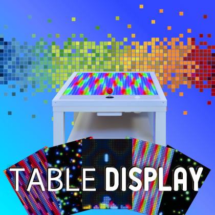
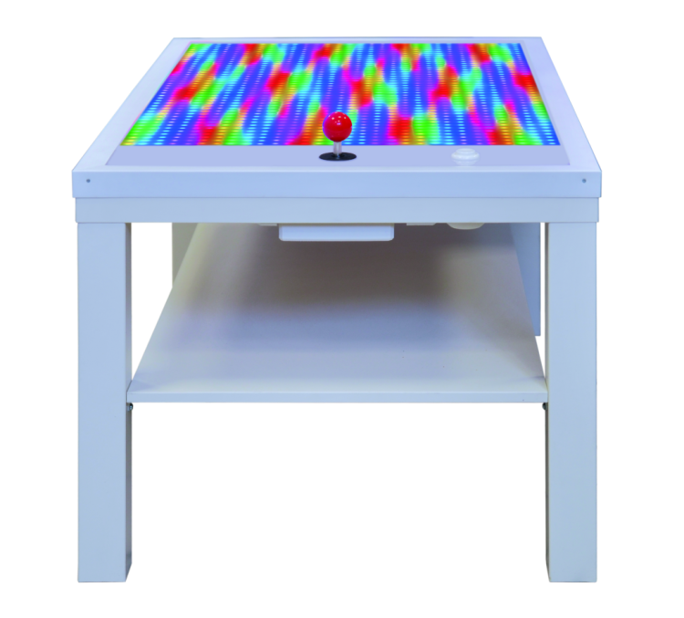
Let’s build an interactive table equipped with a display and manual commands to create everything from videogames to animations for communication, teaching and entertainment.
LED strips with serial control, and Neopixels in particular, allow us to create, when conveniently combined, many lighting effects and even matrix displays that can go up to remarkable dimensions; this is the consideration that sparked the idea for this project, which is basically a videogame table with a huge LED matrix Neopixel display, made of many strips connected in parallel. The initial idea was to create a table capable of implementing a series of lighting effects and at the same time could also be programmed for other uses, e.g. videogames, panel for visualizing moving texts, display for instructional animations etc. We have been built upon that idea because, since the display unit we have created can compose anything, from text to images, a few more lines of code allowed us to build both controls and animation for a videogame, specifically the renowned arcade game Tetris in a tabletop version with a giant screen. In order to create our prototype we’ve started from a base table, a LACK table from IKEA to be more specific (you can find it on www.IKEA.com) that we have picked for its practicality, low cost and high availability (the “DIY furniture” giant has now created a comprehensive network all over Italy and it also sells products online) and because we can easily work with it (the table is made of MDF honeycomb panels, so we can easily “dig” into it and pass the cables).
On the top panel of the IKEA table we applied some RGB LED strips taken from 5 m Neopixel strips, each with 300 LEDs (code STRIP300LED); to be exact, the display is composed of 1260 individually-addressed RGB LEDs.
On the table, we have placed the controlling electronics, which is composed of an Arduino Mega board that interfaces with the player through an arcade joystick (code JOYSTICKASH) and an arcade videogame button (code COM09340).
The joystick has been installed onto the table by hollowing out a cavity and attaching it with some screws, while we have screwed on the button, again after hollowing out an appropriately-sized cavity, with a bigger diameter in the lower part in order to tighten the button with its nut and washer.
Everything is powered by a stabilized AC/DC switching adapter that outputs a 5 V voltage (code RS-150-5).

Electronics
So, let’s take a look at the electronics part of the project, which is basically a display unit and control hardware; the first is, as we already mentioned, a matrix divided into rows, each one composes by a LED strip segment. Using a Neopixel RGB LED strip allows us to address each single LED and choose the color individually, among all the possible tones, and a range of 256 combinations for each base color (therefore we have 256×256×256 combinations!) for a total of 16,777,216 colors. That’s not forgetting that Neopixel, for each RGB LED portion of the strip, integrates a driver and the corresponding RGB LED in SMD and therefore the direct LED control for each one. Data channel for communication is a 5 V-powered oneWire serial channel; Neopixel LEDs are connected in cascade so that the input data line, besides reaching the corresponding controller, is repeated on the output. Communication on the data channel takes place at a maximum rate of 800 Kbps and has an embedded clock. As it is the case for the individual LEDs, we can connect more Neopixel strips in cascade to create various effects. In the strip, the serial control is crucial because otherwise we would need too many lines in order to control the single LEDs composing it, even if we employ a multiplex matrix control system.
As we just mentioned, LEDs of the Neopixel system can be connected in cascade so that the data line of the previous one goes to the next one, but the price to pay is that beyond a certain number of LEDs, control speed must be sensibly reduced; because of this, if you need to create matrixes to display fast-moving graphics it is a better idea to employee multiple lines with a few LEDs each; however this is not our case, because the animation is relatively slow in Tetris.
In short, refresh frequency and therefore the on/off speed of each single LED is inversely proportional to the quantities of LEDs we have to manage.
For each LED strip we can decide what refresh frequency we want to set, in order to make certain lighting effects barely noticeable. In our case, LED scanning frequency is 400 Hz. Maximum data transfer speed influences, controllable LEDs number being equal, the image’s refresh frequency, because all control data travels on a single serial channel; this means that the more LEDs we have to manage, the lower the refresh frequency and therefore the lower the movement speed of the displayed image.
How it works
The control protocol of the Neopixel system calls for the cyclic sending (at a frequency dependent on the frequency of the refresh we want for the display unit) of data strings each one composed of 24 bits divided into three byte groups (therefore 3×8 bits); each byte of a 24 bit string contains the illumination status of each base color in this order: first the eight green bits, then the red ones and finally the blues ones.
Inside each Neopixel strip, every single smart LED is connected in cascade, since data line going into the DI terminal goes out of the DO, which repeats all the data. Reference mass for power and data (it is a single one and connected to the G contact of the strip) is mobile, so it goes in from one end and comes out of the other.
In terms of wiring scheme, we can see that Arduino Mega controls all the strips composing the display unit, using just one data line, so the DI contact of the first segment connects to the I/O of the board and the DO connects to the DI of the following segment, and that DO connects to the DI of the following strip. The connection is repeated until the last segment, which DO contact stays open (no terminal is needed here).
Data line corresponds, in Arduino Mega, to digital 2-pin, set as output.
Strip powering takes place in cascade, but since it is in parallel between start and end, it is actually in parallel, with the exception of the resistance of the strips; for obvious absorbance reasons it cannot be provided by Arduino but it has to come from an external adapter, connected as we are going to explain when we will talk about the construction of the table display unit. Power ground is common with data ground, therefore the GMD contact of Arduino is connected to the GMD of the first strip.
That’s getting back to the Arduino now and we can see that, besides the strips, we have also connected a button and the joystick; the button is normally open and connected to the 7-pin of Arduino and to ground (the pull-up resistance is software-enabled on the corresponding Atmega pin, this way we can do away with an external resistor and simplify the wiring).
The joystick is the classic arcade style joystick, so each one of the four movements corresponds to one button closing; its lever position is therefore detected by means of four digital lines on Arduino Mega, each one configured as an input with an internal firmware-enabled pull-up, which are:
- digital 3-pin 3 for lever up (block rotation);
- digital 4-pin for lever right (right movement of the Tetris block);
- digital 5-pin for lever left (left movement of the Tetris block);
- digital 6-pin for lever down (fast descent of the Tetris block).
Once power is provided, Arduino loads this sketch and periodically checks the button status; at the same time it starts the preset lighting effect. When the button is pushed for the first time the game is launched and Arduino tracks the status of the joystick and the button, in order to move the displayed elements based on the received commands. Synchronization between displaying and commands given by the player through the joystick potentiometers can take place because Arduino Mega checks, with each movement imposed to the object on display, whether the button is pushed or the joystick lever is moving; based on when the command is received, it acts accordingly (for instance, if one block have been already put down and no new block has appeared on screen, it ignores the joystick movement).
Strips management
Images composition on our display is created by indexing one by one, in rapid sequence and line by line, all the 1260 LEDs and by sending to each one of them the data corresponding to the status of each of the RGB diodes composing them, which is expressed through a 0-255 value, where 0 means turned off and 255 means turned on and fully bright. This pattern is scanned multiple times per second in order to trick the eye into seeing a full square each moment, instead of its dot-by-dot composition.
This work required coding a sketch that takes up a lot of memory, that is why we have to use an Arduino Mega, which has been chosen because of the flash of its microcontroller and the size of the programming memory, and not for its number of I/Os, since, as you have just seen, we need so few of them for controlling the system that we might as well use an Arduino Uno.
In order to simplify coding we make use of a dedicated Arduino library which implements the control of Neopixel strips; it is an open source library that can be downloaded from http://fastled.io/ along with a great variety of examples on how to use it.
In fact, we have modified these examples in order to create our table display.
The library is very versatile, so it allows us to create many applications, since it gives us the chance to define the overall number of LEDs composing the display unit, how are they connected (S-shape, as it is our case, in parallel, in series on the long side etc.), width and height of the final panel. The way they are connected is used by the firmware to determine their disposition, so that it knows how to send data at the end of a segment of its strip; if we make a display by connecting the strips in an S-shape, therefore all in series with the end of a strip correspondent to the beginning of the next one, based on the indexing order of the Neopixel LEDs, the firmware has to send data all reversed once it arrives at the indexing of the last LED of a strip, that is it has to start over from the last one of the row and move back toward the first one, and then reverse once again after setting the last one. In conclusion, it must send data to the LEDs in a zigzag motion. If on the other hand, strips are connected in parallel, we have to use multiple I/O lines of Arduino and divide the data of the images to be displayed into multiple rows, addressing each one individually but synchronously. What’s more, if we keep the cascade connection but strips are connected with the last LED connected to the first of the strip below it (when we say last we mean the rightmost one with the leftmost one being the first) data sending takes place in a consecutive manner.
At the beginning of the firmware, the I/O’s used as inputs to detect commands coming from the joystick and the button on the table are defined:
#define ROTATE_PIN 3
#define LEFT_PIN 4
#define RIGHT_PIN 5
#define DOWN_PIN 6
#define PULS 7
Right after that, we define output pins for data and variables:
#define LED_PIN 2
#define COLOR_ORDER GRB
#define CHIPSET WS2812B
#define MATRIX_WIDTH 30
#define MATRIX_HEIGHT 42
#define MATRIX_TYPE VERTICAL_ZIGZAG_MATRIX
Specifically, LED-PIN 2 defines data output and LED-PIN 2 is the line to setting send order for data about the intensity of the three colors of the base LEDs (in this case it’s GRB, that is first value of the green LEDs, then the red ones and finally the blue ones) for each string; CHIPSET WS2812B defines the driver type of each LEDs in the strip, which must be specified because the Neopixel technology can be implemented through more than just one chip.
The MATRIX_WIDTH 30 instruction defines a number of rows (LED strips) while MATRIX_HEIGHT 42 specifies the number of LEDs composing each rows of the matrix visualizer: as you can see, there are 30 LEDs horizontally and 42 vertically, since the visualizer will be arranged vertically, that is rotated 90° and then laid on one of the short sides.
If the display were made of just one strip, MATRIX_would have 1 as a number. Finally, MATRIX_TYPE VERTICAL_ZIGZAG_MATRIX defines the LEDs arrangement and therefore the arrangement of the Neopixel strip segments.
Since we need to set up the library, we cannot load both the firmware’s realizing the proposed applications, e.g. Tetris and the lighting effects panel, despite the memory availability of the ATmega2560; In fact, the two applications require a different configuration of the library. Now, let’s see how the table works in the two provided applications.
Tetris
Once Arduino Mega is launched (that is after powering it on) the firmware will wait for the button to be pressed, because Tetris uses the button in order to start the game; once the game is started, you can control the bricks movements with the joystick: to be specific, when you move the joystick to the left and to right the brick will follow accordingly. Brick rotation can be done by pushing the joystick lever up, while you can speed up the descent by pushing the lever down.
At the end of the game, the player’s score is displayed.
Graphic effects
If we load the graphic effects demo we can, once Arduino Mega is launched, choose which effects to display via the button; moving the joystick lever up or down can increase or decrease the brightness of the LEDs composing the effect, while we can change rotation speed of some of the provided effects by moving the joystick left or right.
Construction
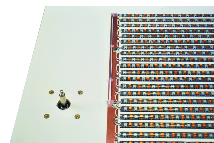
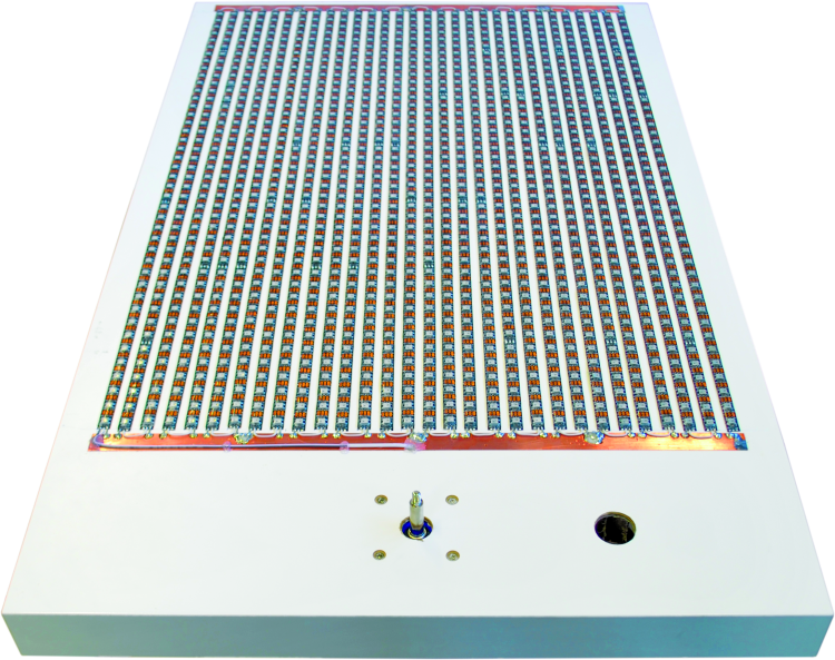
Now, let’s take a look at the construction of the table: we must drill the holes and pass the cables in the IKEA table next to a short side in order to install the button and the joystick. On the remaining part of the table we are going to install the Neopixel strips (that can be found on www.futurashop.it, labeled STRIP300LED) cut in 42 LED portions and arranged along the longer side of the table and side-by-side for a total of 30 strips; this way we are going to create our matrix of 30×42 = 1260 RGB LEDs. The spacing between the strips segments must be adjusted so that the final matrix occupies an overall area of 70 x 49 cm. Data channel for the strips must be installed in series with all of them, therefore the wire coming from the Arduino enter the DI contact of the first strip and comes out of the DI of the last one with a thin (0.22 mm thickness) segment of coated copper wire toward the DI of the adjacent strip and so on. Power and ground must be brought using 0.5 mm thick copper twin leads, because the current absorbed by the system is significant and transportation, if made through wires, would require such a thickness that it would sensibly stick out of the table plane. In order to simplify power connections, the 42 LED segments must be placed with alternated orientation, so that the adjacent ones have the same line near to them, which is alternatively ground and +5 V. So you must start from one side and install the first segment with the GND line close to the edge of the table, then you place the second one next to it oriented in such a way that the 5 V line is next to the 5 V line; in short, it’s just like you had cut and folded the second segment on itself. Then you keep on this way. The photos in these pages will make it clear for you.
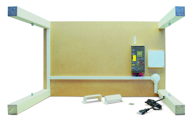
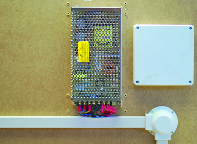
We are using a wall adapter with a stabilized 5 V, 130 W (25 A) output, sold by Futura Elettronica (you can find it on www.futurashop.it with code 8220-RS-150-5); we have placed it under the table, attaching it with some self-threading wood screws and we have protected the screw contacts with a 3-D printed plastic cover (also screwed on).
Strip segments must be powered in parallel by placing on the short side of the matrix some 22 x 0.25 mm copper twin leads, providing an effective section of 5.5 mm² that is necessary in order to withstand the strong current absorbed by the 1260 LEDs that can reach over 20 A. In order to limit voltage fall, which is inevitable since the section is not that big and we are working at 5 V, so even just one volt lost would be unacceptable, we have to apply power to multiple intermediate points for each twin lead: three to be exact, equally spaced. Power will be provided by placing the aforementioned holes between the lead and the table, in order to bring as many 2,5 mm² copper wire segments that will be abundantly tin-soldered in the output point. The segments coming from the bottom side of the board are then to be soldered to the wire coming from the power switching used for the system. The twin lead can be placed 4-5 mm away from the strips. Power must be connected by connecting short 0,5 – 1 mm² naked copper wire segments between the twin lead and the pad of the corresponding line, this is how we need to connect every GND pad of the strip terminals next to the ground twin lead and all the 5V’s next to the positive +5 V twin lead. GND and 5 V contacts are then connected to the twin lead alternatively. DIN data contacts must then be connected, side by side, with coated copper wire bridges with 0.5 mm² section.
The Arduino Mega board must be powered with the same 5 V provided to the strips, by deriving a segment of 2×0,5 mm² red – black twin lead from the + and – terminals of the adapter through a terminal and bringing it to the 5 V and GND contacts of Arduino; in order to simplify the connection, we have to solder a pin for each pin strip, e.g. a jumper, to the terminals of the wires on the Arduino side, by insulating the junction with a heat-shrink tube that we can shrink with a blow dryer.
All the wirings on the bottom of the table are enclosed in white PVC electrical conduits, as you can see in the photos. A conduit segment must carry the power wire ending with the wall plug, and which blue and brown wires must be tightened to the terminals, respectively N (neutral) and L (phase) of the switching power adapter, possibly by equipping them with a forked terminal.
The Arduino board must also be attached to the bottom of the table next to the window we have cut for the joystick, so that we can make the local connections with the button and the joystick itself, keeping the wires short and enclosing everything in a square box for electrical systems. Since the IKEA table is made of MDF honeycomb wood (which is composed of two bottom and top panels – spaced out and tied together by a honeycomb structure of pressed cardboard) it is easy to reach the Arduino Mega with the wires passing from the inner side: the power wire and the two button wires. The conduit you see in the picture carries the 5 V power wires of the strips that will then come out of the top of the table.
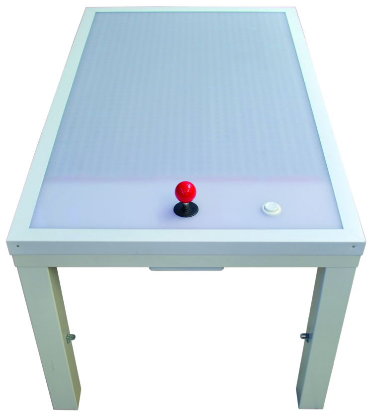
Once connections are made and the data wire has been brought to the table through a dedicated hole next to the strip pad where it will go in first, and once we apply some 0,5×2 cm wood listels on the edges of the table, attached with glue and let dry, you can put a white see-through Plexiglas board on top of it that is 4 mm thick and 55 x 90 cm in area, that would act as a screen and protect the strips, besides making the overall look of the display more pleasant.
The Plexiglas will also cover the joystick and the buttonholes (therefore you will have to drill a hole in it above the holes you have drilled on the table). Which will be tightened on the table itself with specific bolts.
In order to make the table look even better you can apply PVC or white wood corners, just like those used for picture frames, on the four corners of the table, to cover the Plexiglas-listels block.
Listing
#include “FastLED.h”
FASTLED_USING_NAMESPACE
#if FASTLED_VERSION < 3001000
#error “Requires FastLED 3.1 or later; check github for latest code.”
#endif
#define UP_PIN 3
#define LEFT_PIN 4
#define RIGHT_PIN 5
#define DOWN_PIN 6
#define PULS 7
#define DATA_PIN 2
//#define CLK_PIN 4
#define LED_TYPE WS2811
#define COLOR_ORDER GRB
#define NUM_LEDS 1260
CRGB leds[NUM_LEDS];
int BRIGHTNESS = 255;
int cycle = 200;
#define FRAMES_PER_SECOND 520
void setup() {
delay(3000); // 3 second delay for recovery
pinMode(UP_PIN, INPUT_PULLUP);
pinMode(LEFT_PIN, INPUT_PULLUP);
pinMode(RIGHT_PIN, INPUT_PULLUP);
pinMode(DOWN_PIN, INPUT_PULLUP);
pinMode(PULS, INPUT_PULLUP);
Serial.begin(9600);
Serial.println(“TABLE start - by Boris”);
// tell FastLED about the LED strip configuration
FastLED.addLeds<LED_TYPE,DATA_PIN,COLOR_ORDER>(leds, NUM_LEDS).
setCorrection(TypicalLEDStrip);
//FastLED.addLeds<LED_TYPE,DATA_PIN,CLK_PIN,COLOR_ORDER>(leds, NUM_LEDS).
setCorrection(TypicalLEDStrip);
// set master brightness control
FastLED.setBrightness(BRIGHTNESS);
}
typedef void (*SimplePatternList[])();
SimplePatternList gPatterns = { rainbow, rainbowWithGlitter, confetti, sinelon,
juggle, bpm };
uint8_t gCurrentPatternNumber = 0; // Index number of which pattern is current
uint8_t gHue = 0; // rotating “base color” used by many of the patterns
void loop()
{
// Call the current pattern function once, updating the ‘leds’ array
gPatterns[gCurrentPatternNumber]();
// send the ‘leds’ array out to the actual LED strip
FastLED.show();
// insert a delay to keep the framerate modest
FastLED.delay(1000/FRAMES_PER_SECOND);
// do some periodic updates
EVERY_N_MILLISECONDS( cycle ) { gHue++; } // slowly cycle the “base color”
through the rainbow
if ( digitalRead(PULS)== LOW){
nextPattern();
delay(1000);
}
if ( digitalRead(DOWN_PIN)== LOW){
if (BRIGHTNESS>10) {
BRIGHTNESS=BRIGHTNESS-10;
}
FastLED.setBrightness(BRIGHTNESS);
Serial.println(BRIGHTNESS);
}
if ( digitalRead(UP_PIN)== LOW){
if (BRIGHTNESS<245) {
BRIGHTNESS=BRIGHTNESS+10;
}
FastLED.setBrightness(BRIGHTNESS);
Serial.println(BRIGHTNESS);
}

if ( digitalRead(LEFT_PIN)== LOW){
if (cycle>10) {
cycle=cycle-10;
}
Serial.println(cycle);
}
if ( digitalRead(RIGHT_PIN)== LOW){
if (cycle<245) {
cycle=cycle+10;
}
Serial.println(cycle);
}
//EVERY_N_SECONDS( 100 ) { nextPattern(); } // change patterns periodically
}
#define ARRAY_SIZE(A) (sizeof(A) / sizeof((A)[0]))
void nextPattern()
{
gCurrentPatternNumber = (gCurrentPatternNumber + 1) % ARRAY_SIZE( gPatterns);
Serial.println(“nextPattern”);
}
void rainbow()
{
fill_rainbow( leds, NUM_LEDS, gHue, 7);
}
void rainbowWithGlitter()
{
rainbow();
addGlitter(80);
}
void addGlitter( fract8 chanceOfGlitter)
{
if( random8() < chanceOfGlitter) {
leds[ random16(NUM_LEDS) ] += CRGB::White;
}
}
void confetti()
{
fadeToBlackBy( leds, NUM_LEDS, 10);
int pos = random16(NUM_LEDS);
leds[pos] += CHSV( gHue + random8(64), 200, 255);
}
void sinelon()
{
fadeToBlackBy( leds, NUM_LEDS, 20);
int pos = beatsin16(13,0,NUM_LEDS);
leds[pos] += CHSV( gHue, 255, 192);
}
void bpm()
{
uint8_t BeatsPerMinute = 62;
CRGBPalette16 palette = PartyColors_p;
uint8_t beat = beatsin8( BeatsPerMinute, 64, 255);
for( int i = 0; i < NUM_LEDS; i++) { //9948
leds[i] = ColorFromPalette(palette, gHue+(i*2), beat-gHue+(i*10));
}
}
void juggle() {
fadeToBlackBy( leds, NUM_LEDS, 20);
byte dothue = 0;
for( int i = 0; i < 8; i++) {
leds[beatsin16(i+7,0,NUM_LEDS)] |= CHSV(dothue, 200, 255);
dothue += 32;
}
}
Firmware
The appropriate sketch for the application must be loaded on the Arduino Mega, using a USB cable for connecting to the computer on which we will do the programming. We have provided two sketches that can be found and downloaded here: they are called Demo.ino (it is a series of animations reproduced one after another in order to show the potential of the LED screen) and Tetris.ino (the namesake game). In these pages, we’re only going to publish the Demo.ino sketch for space reasons, which implements an application of the FastLED 3.1 library (or newer versions). The code sequentially executes a series of lighting effects (they repeat every 100 seconds until external intervention, e.g. until the button is pressed) and they rotate. The firmware is derived from Mark Kriegsman’s.
Each lighting effect is managed by a routine and they are rainbow, rainbow with glitter (colored bar and flashing dots), add glitter (flashing dots), confetti (random colored spots flashing and fading out), sinelon (colored dots zigzagging and fading out), void bpm (colored pulsing strips) and void juggle (eight colored dots interest gating).
During execution, by moving the joystick lever up or down you can increase or decrease speed, while by moving it right or left you can speed up or slow down the execution.
Remember that you can upload only one sketch at the time on Arduino Mega (so you have to choose between Tetris and the graphics demo): open it in the Arduino IDE, compile it and send it, then once sent please check if the panel starts to display the lighting effects.
Have fun!
From openstore
STRIP 300 LED RGB ADDRESSABLE WS2812B- NEOPIXEL
SWITCHING POWER SUPPLY 5V DC 130W
