- makeITcircular 2024 content launched – Part of Maker Faire Rome 2024Posted 2 weeks ago
- Application For Maker Faire Rome 2024: Deadline June 20thPosted 2 months ago
- Building a 3D Digital Clock with ArduinoPosted 7 months ago
- Creating a controller for Minecraft with realistic body movements using ArduinoPosted 7 months ago
- Snowflake with ArduinoPosted 8 months ago
- Holographic Christmas TreePosted 8 months ago
- Segstick: Build Your Own Self-Balancing Vehicle in Just 2 Days with ArduinoPosted 8 months ago
- ZSWatch: An Open-Source Smartwatch Project Based on the Zephyr Operating SystemPosted 9 months ago
- What is IoT and which devices to usePosted 9 months ago
- Maker Faire Rome Unveils Thrilling “Padel Smash Future” Pavilion for Sports EnthusiastsPosted 10 months ago
SLA 3d Printer – the FSLA
Web site:
http://www.instructables.com/id/FSLA-3d-Printer/Project Summary:
This guide covers the construction and installation of a "low cost" 3d printer SLA. The project began for me during Christmas of the year 2014, a time when I was very
busy with another project that completely absorbed me. During the holidays I decided (unconsciously) to distract myself with the idea of creating a printer based on
photosensitive resin technology. The idea was to control a UV laser module mounted on a central joint and tilt it to reach all points of the plan. After have finished it and
put into operation, I realized that it presents several problems. One of the biggest problems is related to the precision of the movement (although the economic stepper
drivers divide steps many times, the single microstep is not reliable for such operation), another big problem is the deformation of the beam when it reach the base and
takes different forms depending on where it is. After some tests and prints not very satisfactory I decided to switch to traditional Cartesian architecture.
Finally, the entire work that naively thought I conclude by January, took three months, but I was happy with the results!
Full Project:
At this point, better to step back and talk a little of the SLA printing technique. This type of printing is based on the principle that it is possible to catalyze a small amount of resin by hitting it with a coherent beam of photons.

The resins available on the market for this purpose are sensitive to ultraviolet, 405nm. I’ve used the makerjuice natual with satisfaction. From the practical point of view this means to catalyze layer by layer using a uv laser, where each layer represents a section of the object that we want to achieve. To catalyze a layer of the desired thickness (ex. 0.1mm), there are two basic techniques. One technique is to catalyze the layers on a plate which gradually descends into a tank full of resin, each upper layer catalyzes over the previous. The floor will drop always of the same size with respect to the resin surface, which corresponds to the thickness of the layer. A second method (the one that I chose) provides a UV-transparent vessel, containing the resin and below the laser that catalyzes the resin. To build the model, the printer move the plane inside of the vessel, in order to leave the desired thickness between the plane itself and the bottom of the tank. Between one layer and the next, the plane is lifted and the piece has to remain attached to it, in order to leave the free space for the next layer. Both methods are valid but have different problems. The first method requires a tank with a volume equal to the maximum build volume and filled at least to the height of the piece (a problem for those who do not frequently use the resin that would remain long in or you have to remove it frequently). It also requires a reliable system to control the level of resin and the sinking of the floor, because the volume variation that undergoes the resin which catalyzes affects the result. The second method is more simpler but also undergoes to several problems. The most annoying is the fact that the resin adheres when catalyzes both to the plate and to the bottom of the vessel, and then when the plan lift to the next layer is necessary to ensure that the material remains attached to the plate and not to the tank, otherwise the print fails. To avoid this we need to create a fund in the vessel but transparent to
UV, since the laser must pass through it. It is also important to avoid the “sucker effect” which results when trying to detach two surfaces adherent, applying a force perpendicular to the plane. For this it is expected in the printer a movement of the tilted tub, to remove the resin from the plane starting from an edge.
List of Materials
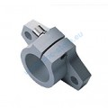


4x: 20mm rod support (0612-SHF20) for Z axis
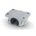
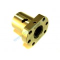
2x: 20mm bearing support (0548-TBR20UU) for the screw of Z axis
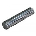
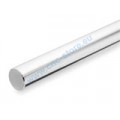
2x: 20mm rod (ST20)
4x: foot (TCOL00157398)
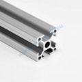
4x: 30x30x240 C.8 alluminium profile (PR0300308) for bottom and top (should be M8 threaded on top and bottom)
4x: 30x30x300 C.8 alluminium profile (PR0300308) for bottom and top (should be M8 threaded on top and bottom)
4x: 30x30R rounded alluminium profile (PR030030R) for the jambs (should be M8 threaded on top and bottom)
1x: 45x90x200 alluminium profile (PR0300908) for plate support
2x: 60x30x290 alluminium plate for Z axis (see the dxf for more detail)
2x: D12 carriage for Z axis (0548-TBR20UU)
1x: 350x290x3 alluminium plate for vessel plate support (see dxf for more detail)
6x: clamping angles 25×40 (SQ025040) to mount Z axis to the structure
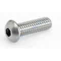
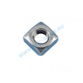
16x: M8 bolts + C.8 square nuts
1x: reprap’s compatible 3d printer electronics (Arduino based)
1x: reprap’s compatible lcd
3x: stepper motors NEMA17 0.9°/step for X Y Z axis
1x: stepper motor NEMA17/gearboxe 0.35°/step for vessel
1x: screw + ball nut for Z axis
a bunch of 3d printed parts for carriege, supports etc.. (see the file attached for stl)
This material should be found on shops who sell 3d printers or cnc mechanical parts.
I found everything cnc-store with a good price and service.
Mechanics


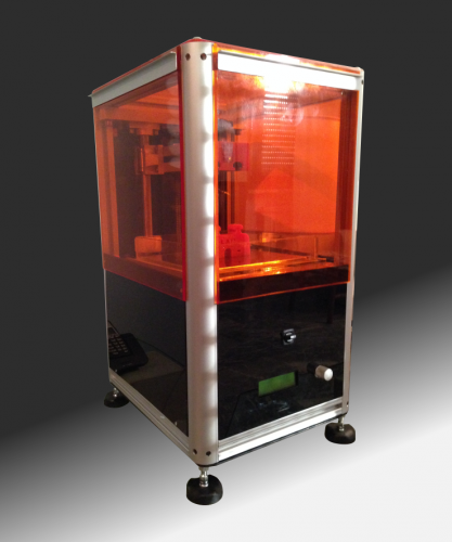
I called the printer FSLA because it is a pun between Fla (my name) and
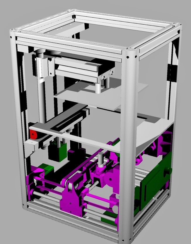
SLA (Stereolithography). The printer has an building volume of 150x150x130mm, which is bigger of what you commonly find in sla low cost printer..
The structure is based on extruded aluminum sections of 30mm side, to which are mounted the rods on which slide the carriages for the movement of the laser, the support for the tub and the Z axis .
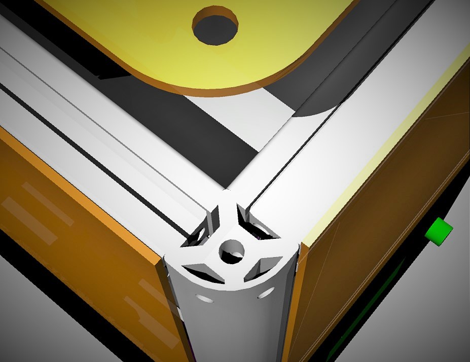
The main frame is built around the 4 jambs, which are 30×30 rounded sections, pretty nice looking i think :)
To mount the 4 30×30 square sections for the edges you should make 4 holes on the rounded sections. The holes have to be 15mm far from top and bottom and should pass in the middle of the central cavity of the sections, where the bolt’s head has to be. Every edge is fixed to the jamb through an M8 rounded bolt and the hole is where the allen key passes to tighten the bolt.
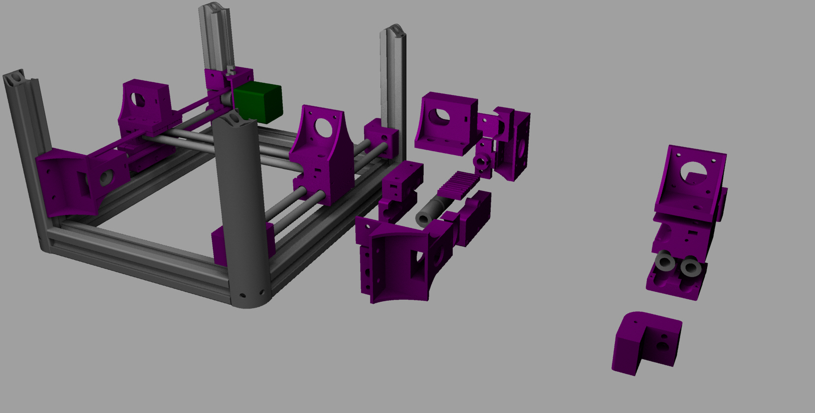
All components necessary for the construction of the axes X and Y can be printed from a common FDM printer, personally I preferred the PLA as a material, but i think that also the abs or nylon are perfect. Attached to this guide you can find all stl files for printing. To allow the perfect sliding of the carriages, I used sliding bearings, while as regards the traction straps I used 5mm pitch 10mm wide. For X, Y and Z i have used motors NEMA17 model 42BYGHM809 (0.9 ° / step) while the inclination of the tub I used a motor 42STH38, always NEMA17 with gearbox (0:35 ° / step). To ensure a good strength of the machine I made some aluminum parts, in particular the Z axis and the support of the vessel. For the realization of these parts i have attached files dxf and gcode that I used for cutting with cnc milling.
As regards the Z axis, instead of using a belt for movement I decided to use a screw with a ball nut. This type of mechanism is expensive but allows you to move the plane on the vertical axis greatly reducing friction and games. The two vertical bars are large, but it is necessary if you want to have a solid Z-axis.
The Vessel
Regarding the construction of the tank, I got cut from my glass glazier some piece of glass and I have assembled it with acetic silicone. We must pay special attention to the non-stick coating. This is vital for the success of the prints !! In fact it is necessary that the resin adheres better to the plane then to the tub, so that there remain attached parts of prints. For this I used a two-component liquid silicone and UV transparent, the same that is used to protect the photovoltaic panels. The only ones that I have tried and found to be good for this purpose are the Sylgard 184 and QSIL 216, that I ended up using for the lower price and availability. When depositing the silicone is important to ensure that the tank is horizontal, so that the layer is of uniform thickness, it is also advisable to remove the air bubbles that will remain encapsulated, manually or by means of a bell. To make sure that the tank is secured to the mount, I’ve used two aluminum rails where the vessel borders flows within.
Electronics & Firmware
The laser I used is a module from 120mA 405nm, this module is controlled
by a power supply which, in addition to adjusting the current allows a digital control input up to 20KHz. This allowed me to use a pin of uC to vary the laser power. To prevent the environmental UV radiation do harden the resin, I have realized some methacrylate panels, some transparent orange and others black, where the internal parts are to be hidden.
As regards the electronics I used the board produced by the www.futurashop.it company who have realized it for their 3drag printer. I chose it because I think it is very well done, but with minor changes to the firmware you can use any other electronics designed for 3d printers based on Arduino.
The firmware from where I started is the well known Marlin, making the appropriate changes in order to make it operational for my laser printer. For example, the E axis, which is normally used for pushing the material, in my case was used to tilt the vessel between one layer and another. For the pwm control of the uv laser (by varying the duty cycle it is possible to change the laser power) I used a pin of uC that would normally be used to control the power mosfet of the heated surface.
You can check out the firmware for the FSLA printer at my github
https://github.com/flavioansovini/FSLAprinter
Can also be used to print PCB!!
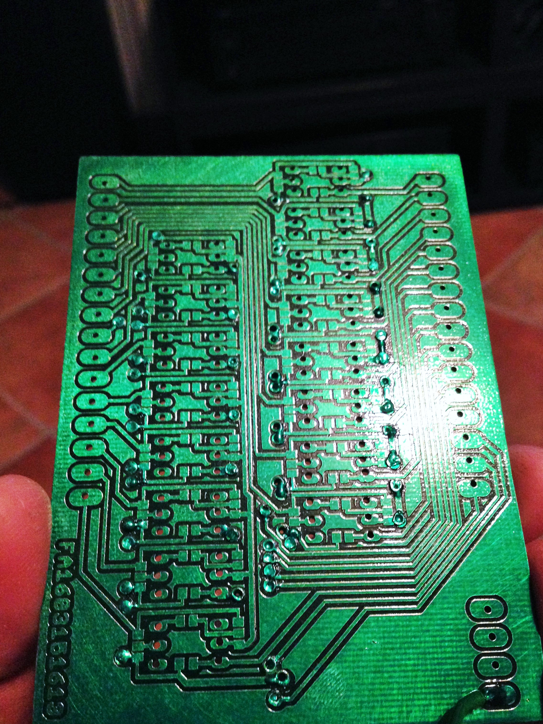
This printer can also be considered “mutipurpose” because I’ve used it with satisfaction to realize pcb.
In fact the laser that is used to catalyze the resin can also be used to impress the photoresist present on the presensitized boards for photoetching.
To do it, I normally design the pcb using Eagle PCB and then I produce the gcode using a modified version of a well known ulp for eaglePCB, PCB-Gcode.
To impress the presensitized board you have to remove the vessel and mount the board to the plate using 2 screws.
If the board is a 2 side pcb you have to print the top side first and then rotate the board on the plate and print the bottom side. In order to align the two prints you have to take a precise measure of the offset on the x axis when you mirror the board and a rotation also (because you’ll probably won’t be enought precise with holes and the costruction itself). This is not an easy process, but when you’ve done it you have to modify my setup with yours, in the “/scr/pcb2FSLAprinter.scr” file, before launching the script inside eagle pcb.
After that the prints are done you can treat the board like in a common photoprinting process, so you can use the sodium hydroxide and then hydrogen peroxide to remove the copper.
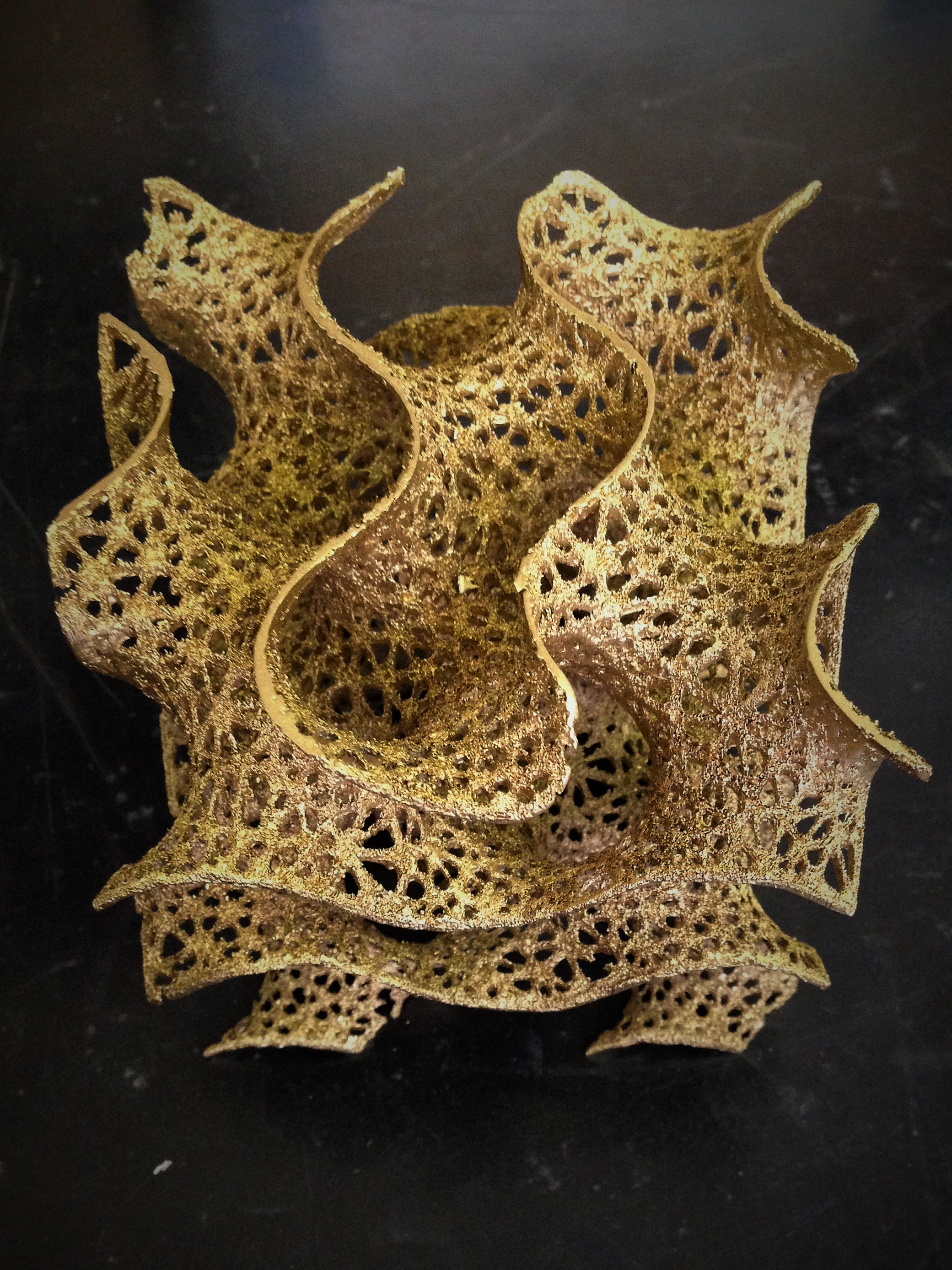
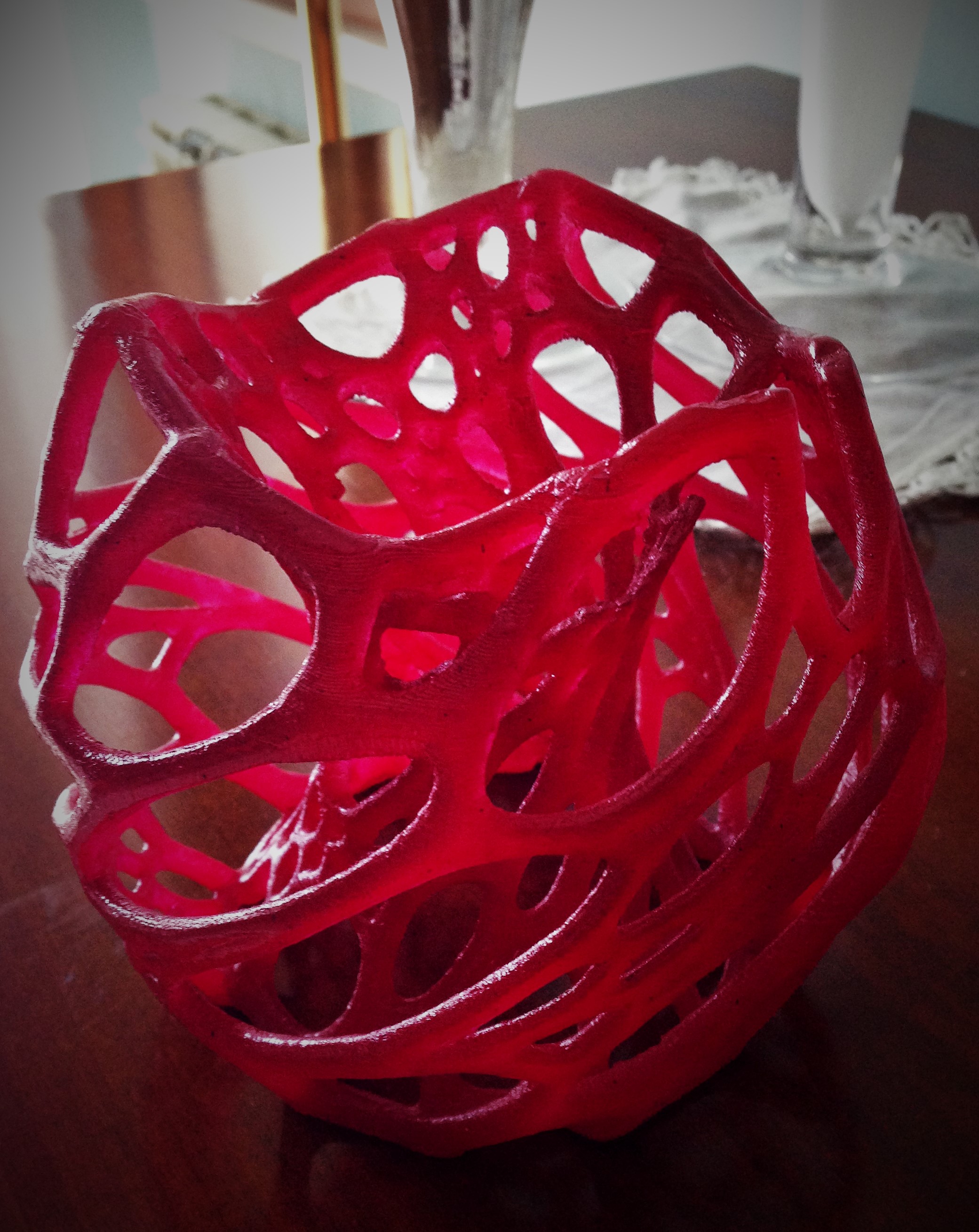
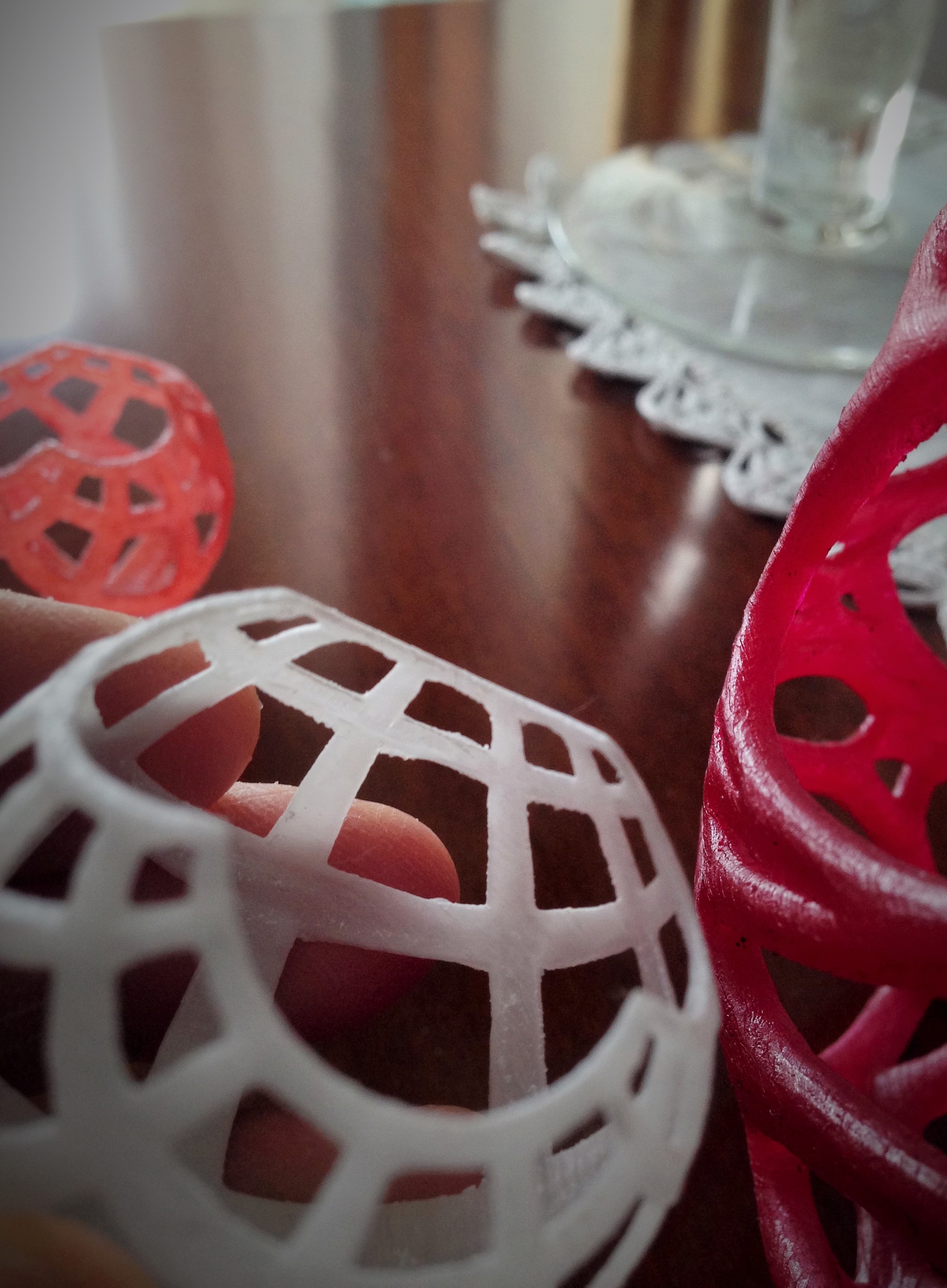
I think that this kind of printer is more useful for who like to print at higher resolution but pieces not with mechanical purpose. This is because the prints are made in resin, and even if there are several kind of uv resin, the prints are more for action figure or objects of design, not much for who wants to build mechanisms. This is in my experiece until now, but every day there are news about UV resins and probably there already is something better around for this.
The building of this machine was a very nice adventure, and was more hard of what i aspected to be, but at the end i think that the resault is really nice!!
This project has a not negligible cost, and is not so easy to build, but when it will work (and it will work :) ) will be a really good satisfaction for you.
I know that many things are still to be said in order to have full info to build the machine, but I hope that the images can help to anyone who wants to try to build it. And of course i’m here if anybody need some more informations.
If you liked this guide please go and vote it at instructable.com
Flavio
Circuit diagram:


-
 Arduino ISP (In System Programming) and stand-alone circuits
We use an Arduino to program other ATmega without...
- Posted 12 years ago
-

-

-
 GSM GPS shield for Arduino
Shield for Arduino designed and based on the module...
- Posted 12 years ago
-
 Small Breakout for SIM900 GSM Module
Some post ago we presented a PCB to mount...
- Posted 13 years ago
-
 makeITcircular 2024 content launched – Part of Maker Faire Rome 2024
Applications to MakeITcircular must be in by October 3,...
- Posted 2 weeks ago
-
 SONY color camera module, 700 TV Lines
Color camera module equipped with a 1/3″ CCD sensor...
- Posted 3 weeks ago
-
 ESP32 Low Power Module
ESP32 Low Power Module, based on Espressif’s SoC capable...
- Posted 2 months ago
-

-
 Application For Maker Faire Rome 2024: Deadline June 20th
Learn More About the Ideas, Makers + Projects at...
- Posted 2 months ago
One Comment