Description

3D Sensor Prototype (Rev. 2) Demo
External Links
The Challenge
The 3D positioning and gesture tracking technology incorporated in all of today’s sensors, such as the Kinect Sensor or Leap Motion Controller, as well as the camera/sensor included in the VR bundles of Oculus Rift or HTC Vive, is based on IR.
The challenge that this project addresses is to develop a sensor device, alternative to the 3D IR camera/sensor, which –
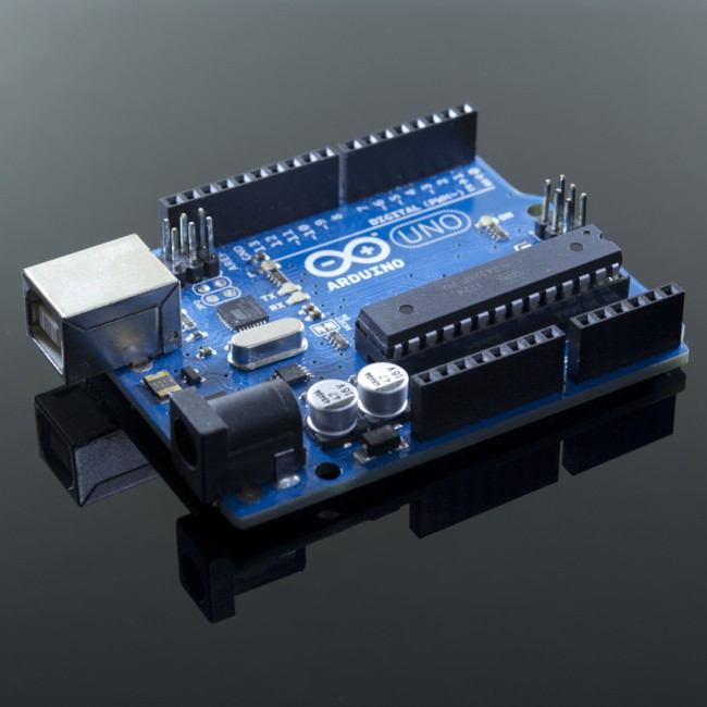
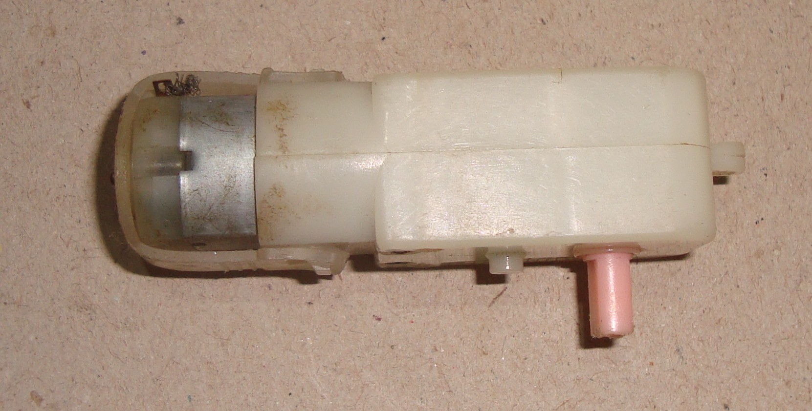
- costs merely 6.4%, ($7.6, i.e, counterfeit Arduino Uno + plastic gear motor) compared to 2 x Oculus Sensor (2 x $59 as stated in https://www.oculus.com/accessories/), and also much less than other IR cameras/sensors.
- has completely open source hardware (an Arduino project), software and tracking algorithms, as opposed to the hardware and tracking algorithms of those IR cameras/sensors.
- is precise up to 1 mm, along all 3 dimensions, as opposed to a resolution of around 1 cm provided by today’s IR camera/sensors.
- can be reconstructed from scratch in a mere 10 minutes (10 min if 3D printed, 4 hrs if manually constructed), and has very simple schematics and build design.
- as opposed to IR cameras/sensors is able to see beyond opaque obstruction, and whose tracking precision is not compromised owing to white or shiny surfaces.
Brief Explanation of Tracking Algorithm
- Water potentiometer gives the voltage at tip of the stylus.
- Voltage gives a plane containing the tip of the stylus.
- Gear motor rotates the sensor to give 3 different voltages for 3 different angular positions, for the same fixed stylus tip.
- 3 different voltages implies 3 non-parallel plane equations.
- 3 non-parallel planes intersect at a unique point.
- x, y, z coordinates of that point is the stylus tip’s location.
Detailed Explanation of Tracking Algorithm
(This video demonstrates the water potentiometer technique used in this project and practically verifies the differential equations below.)
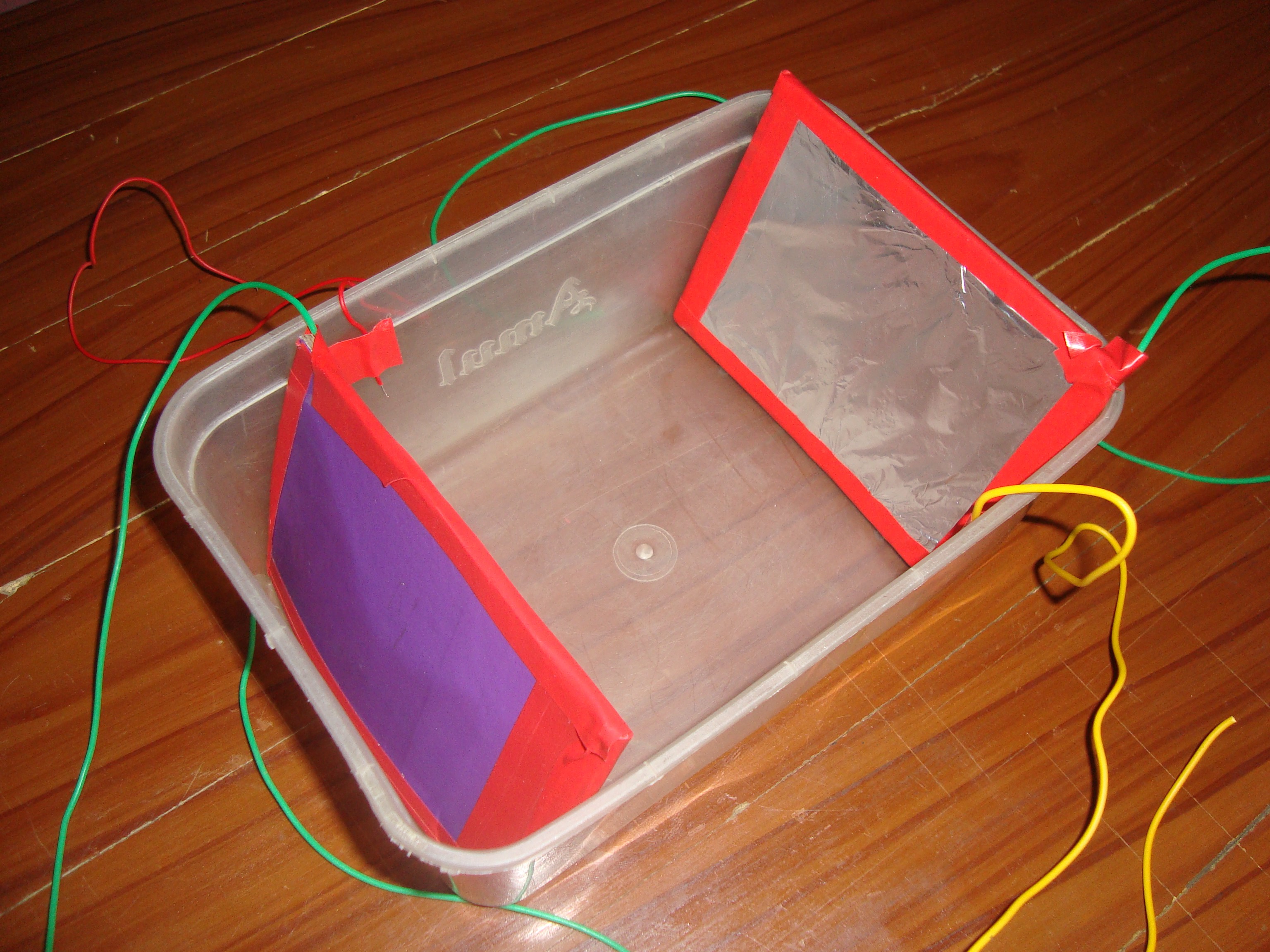
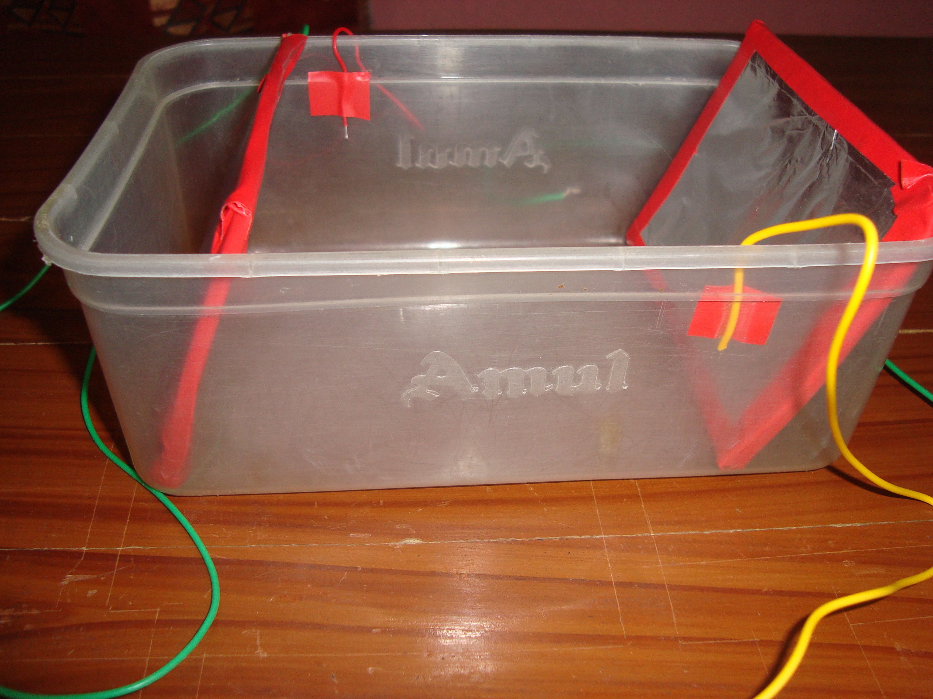
The basic idea behind this sensor is the use of a parallelopiped water container as a water potentiometer device. It is similar to a 3-pin slide pot used in electronic circuits, with the 2 aluminum electrodes equivalent to the 2 end pins of a slide pot, and the stylus is equivalent to the middle pin (voltage output) of a slide potentiometer. Since water is an electrolyte, its composition, hence, conductivity does not remain uniform on passing current through it. Thus, to retain uniform composition, electrolysis must be minimized. In order to minimize electrolysis, the following adaptations have been made –
- The microcontroller C++ code constantly keeps swapping over the polarity of voltage drop across the water, to cancel out the disturbance in its composition.
- The microcontroller C++ code has been optimized for minimum cycle time period, to maximize the frequency of swapping of the voltage drop polarity.
Owing to the above adaptations, the water always has uniform composition and hence, uniform conductivity at all points inside water. Thus, the voltage varies linearly with respect to the displacement from ground electrode.
A parallel pair of aluminum sheet electrodes are attached to the water container at two opposite faces, and inclined at an angle ‘alpha’ (= 75 degrees or (5/12)*PI radians) to the horizontal base of the parallelopiped container. These two apply a voltage drop of 5 volt across the water. A metal pin, connected to Arduino Uno’s ADC input, is attached to the tip of the stylus. This pin tracks the voltage at the tip of the stylus, i.e., output voltage of the water potentiometer, when dipped into the water.
Derivation of Water Potentiometer Output

Derivation of Plane Equation


Due to electroplating on the aluminum electrodes, some voltage drop is consumed at the 2 electrodes, so this offset in voltage at the ends of the potentiometer needs to be corrected, or else voltage would not be linear, i.e., directly proportional to the horizontal displacement. In other words, the voltage drops linearly between the 2 offset pins (and NOT between the 2 electrodes, due to electroplating on the 2 electrodes). The variables l and m in all above equations must eventually be replaced by l_new and m_new respectively.

Extended Applications
- Sculpting in Virtual Reality ( interfaced with a VR headset such the Google Cardboard, Oculus Rift , or HTC Vive ).
- Painting in Virtual Reality ( interfaced with a VR headset such the Google Cardboard, Oculus Rift , or HTC Vive ).
- Modelling in Virtual Reality ( interfaced with a VR headset such the Google Cardboard, Oculus Rift , or HTC Vive ).
- Interacting with holograms viewed from devices such as Microsoft Hololens.
- CGI designing.
- Virtually building models to be 3D printed.
A World Changing Idea and How it Benefits the Society
- This sensor can be quickly and easily be constructed even by non-engineers and high school students. So it can be used for a more interactive and fun way of learning science by interacting with holograms.
- This sensor is a low cost alternative to IR cameras/sensors for amateur or professional artists.
- Since its tracking algorithms and hardware is completely open source, it can be developed by researchers around the world to further minimize its cost and achieve a greater deal of precision.
- Imagine one of this low cost DIY sensor at every home on the planet. It is surely going to revolutionize the way we think and begin a new era of computing since it enables 3D interaction with computers.
Build Instructions
- Construct the Sensor

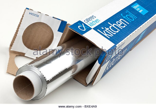
Cut 2 square pieces from the aluminum foil having breadth of the plastic cuboid container box and height a little greater than that of the container. Stick each square lamina on a plastic base of exactly equal dimensions as the lamina. Fix these 2 plates to the plastic cuboidal container box at an angle of 75 degrees or (5/12)*PI radians to the horizontal base.
- Hook Up the Sensor Wires


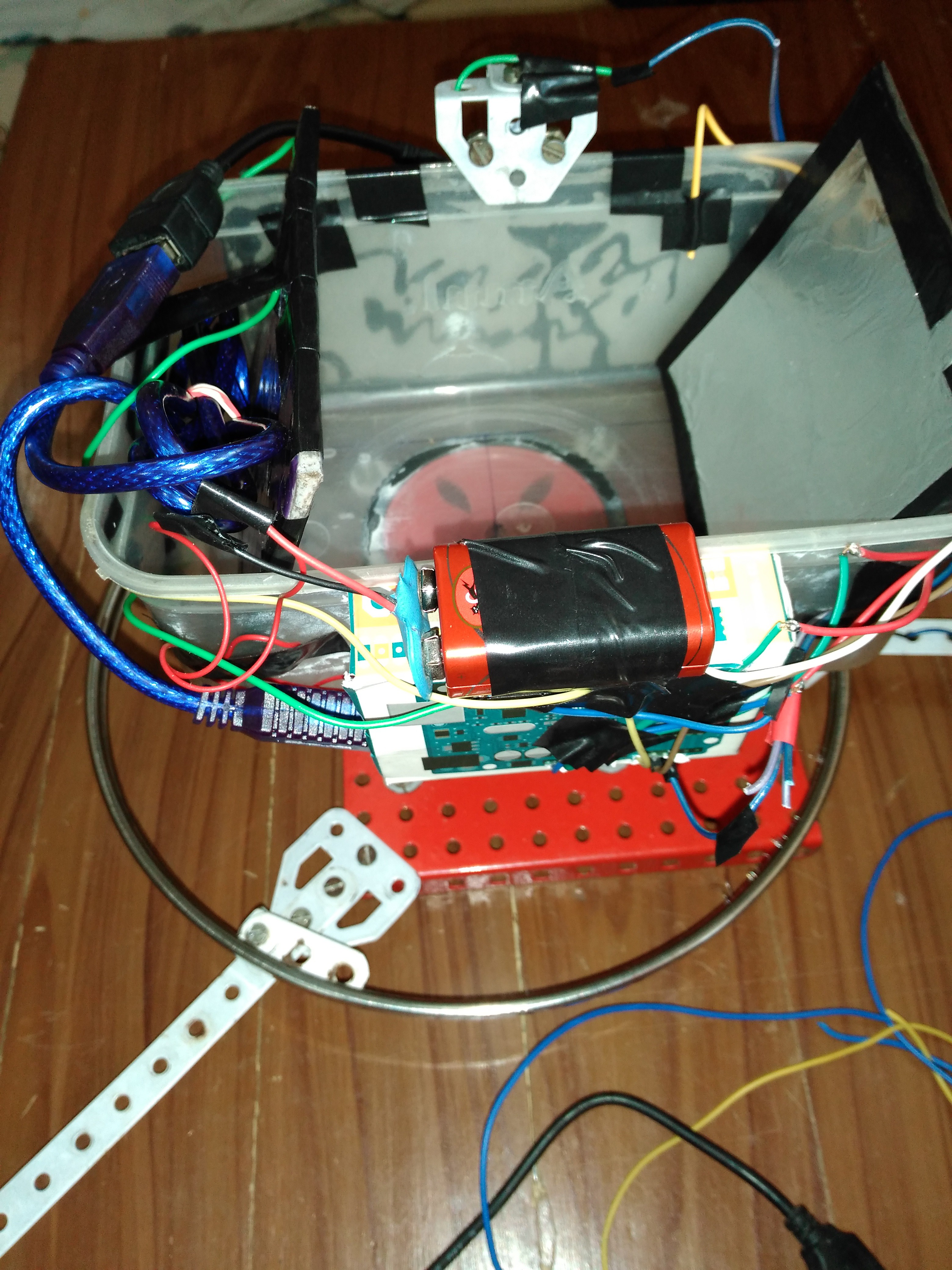
Connect a wire from from one of those electrode plates to digital pin 2 of the Arduino Uno. Now this electrode plate becomes ELECTRODE_0.
Connect another wire from from the other of those electrode plates to digital pin 3 of the Arduino Uno. Now this electrode plate becomes ELECTRODE_1.
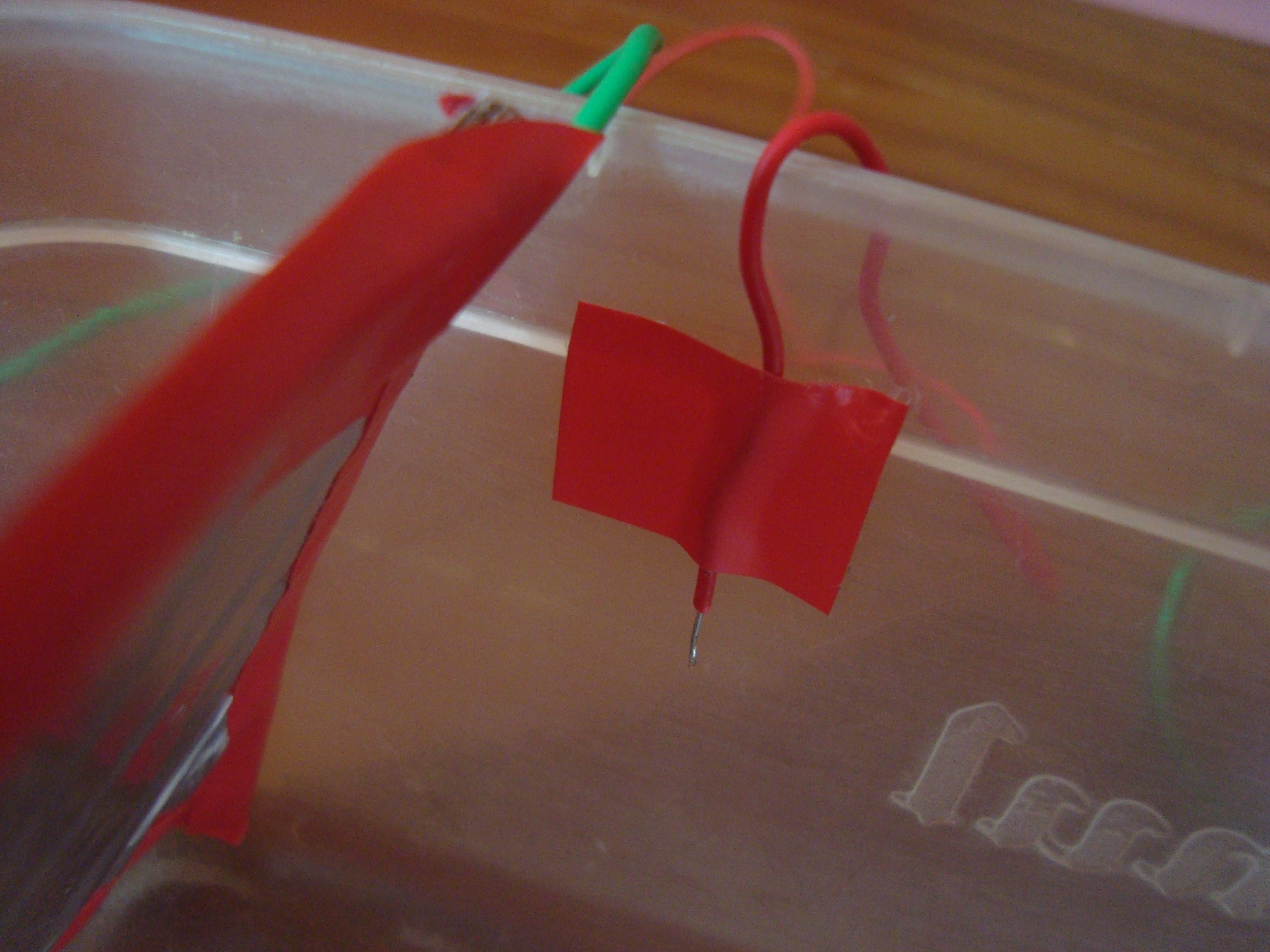
Now, fix one wire to the inner side of the plastic water container box at some distance from ELECTRODE_0. Connect this wire to analog pin A1 of the Arduino Uno. Now, this pin becomes OFFSET_0.
Now, fix another wire to the inner side of the plastic water container box at some distance from ELECTRODE_1. Connect this wire to analog pin A2 of the Arduino Uno. Now, this pin becomes OFFSET_1.
- The Stylus
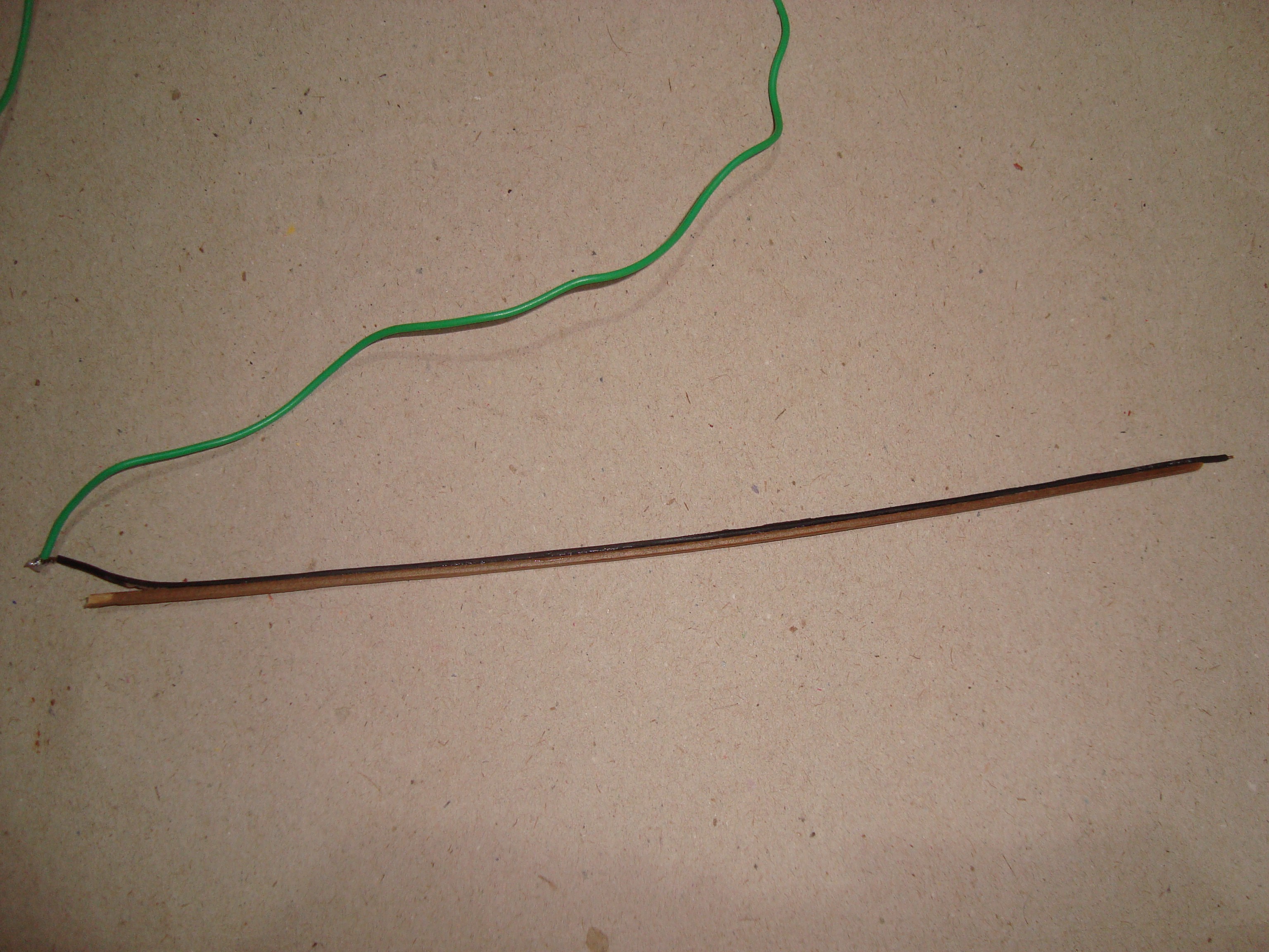
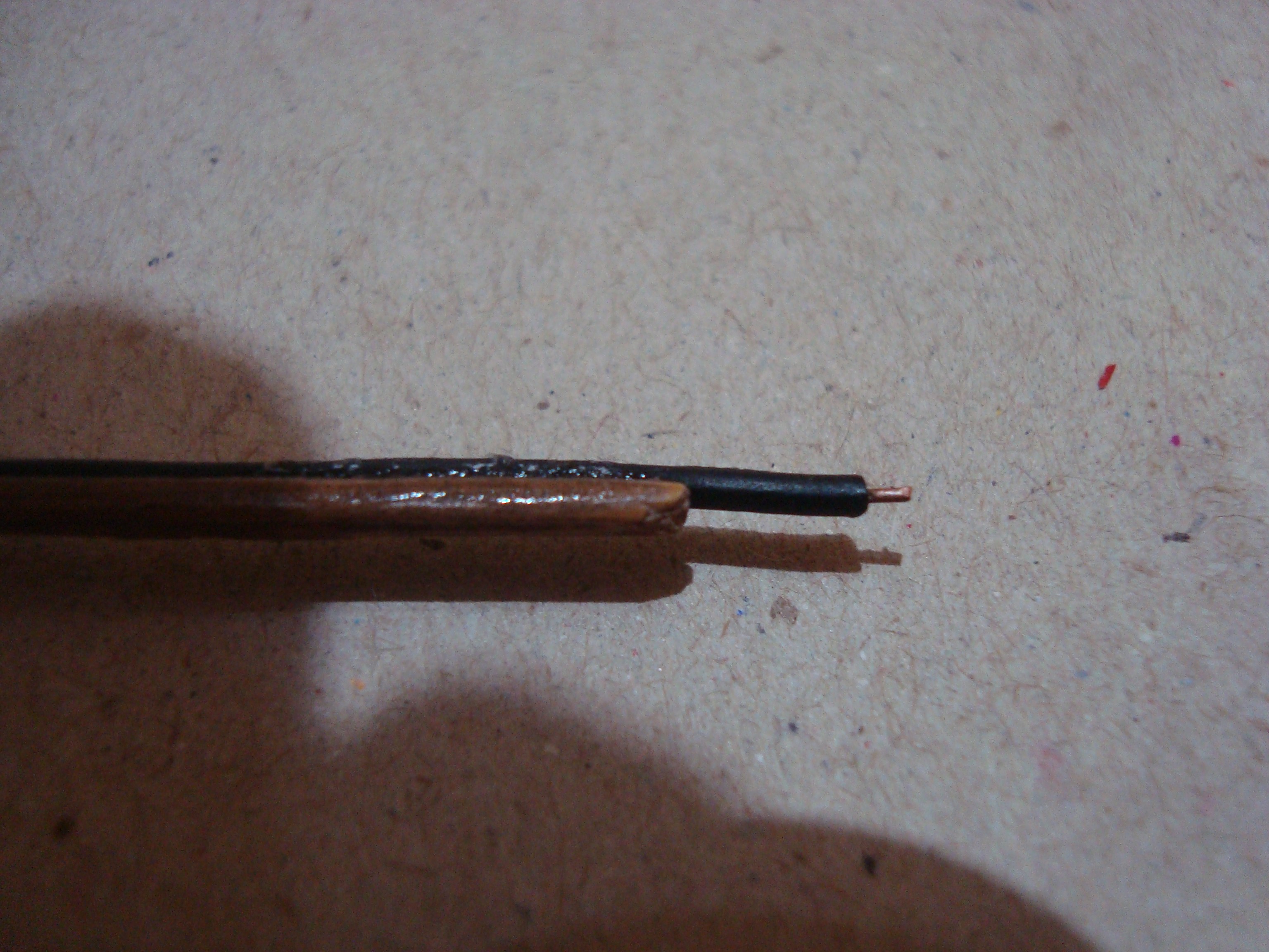
I used a thin wooden stylus. But you can use a sturdy stylus of any non-conductive material. The stylus must be as thin as possible to minimize ripples and disturbance in the water. Fix an insulated wire along its length and strip off just a tiny portion at one end. The coordinates of this tip will be tracked by the 3D sensor. Connect the other end to the metallic ring. Be sure to that the wire is tightly attached to the non-conductive stick and is not separated from the stick at any point. This is to eliminate unnecessary disturbance in the water.
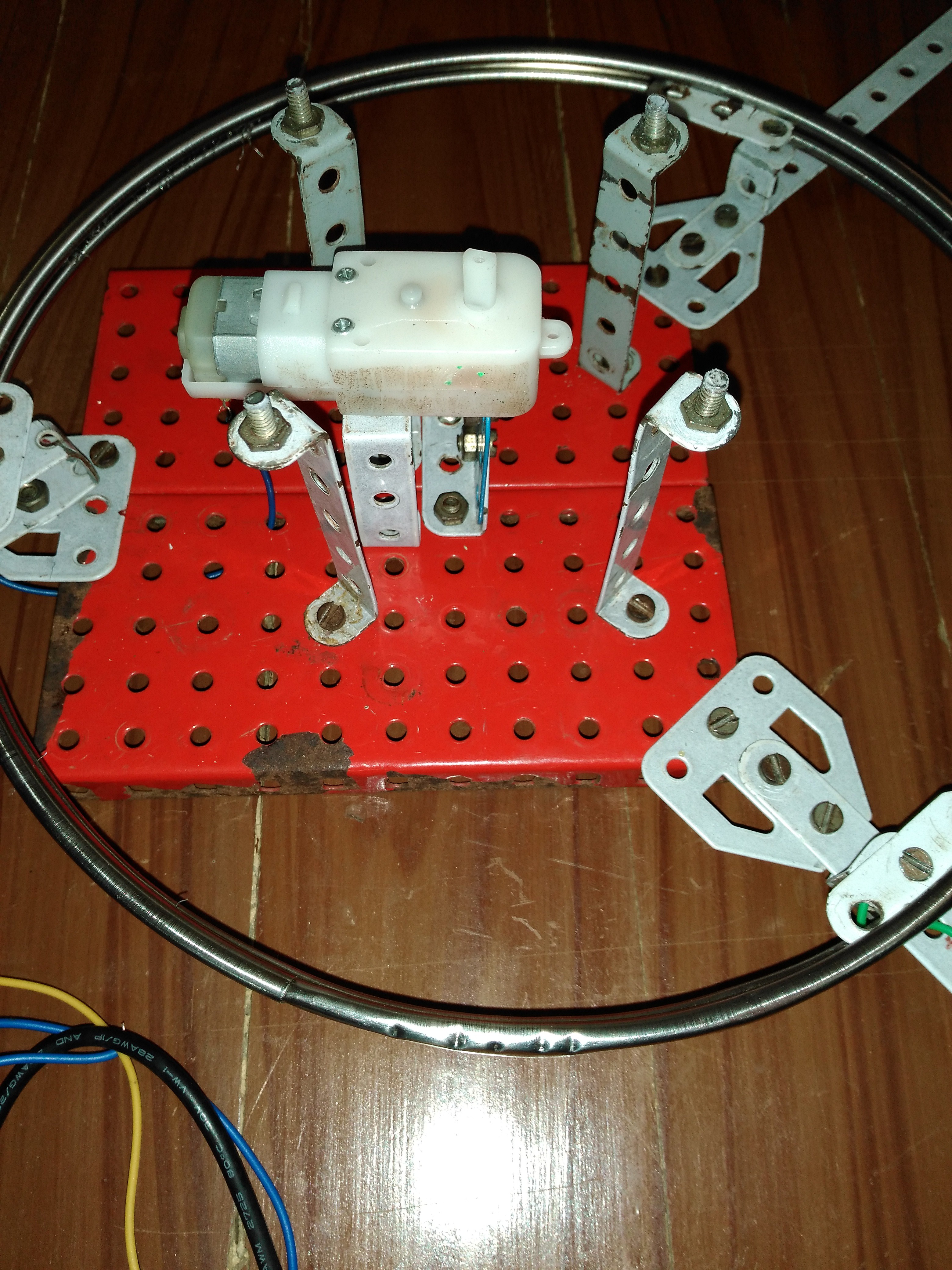
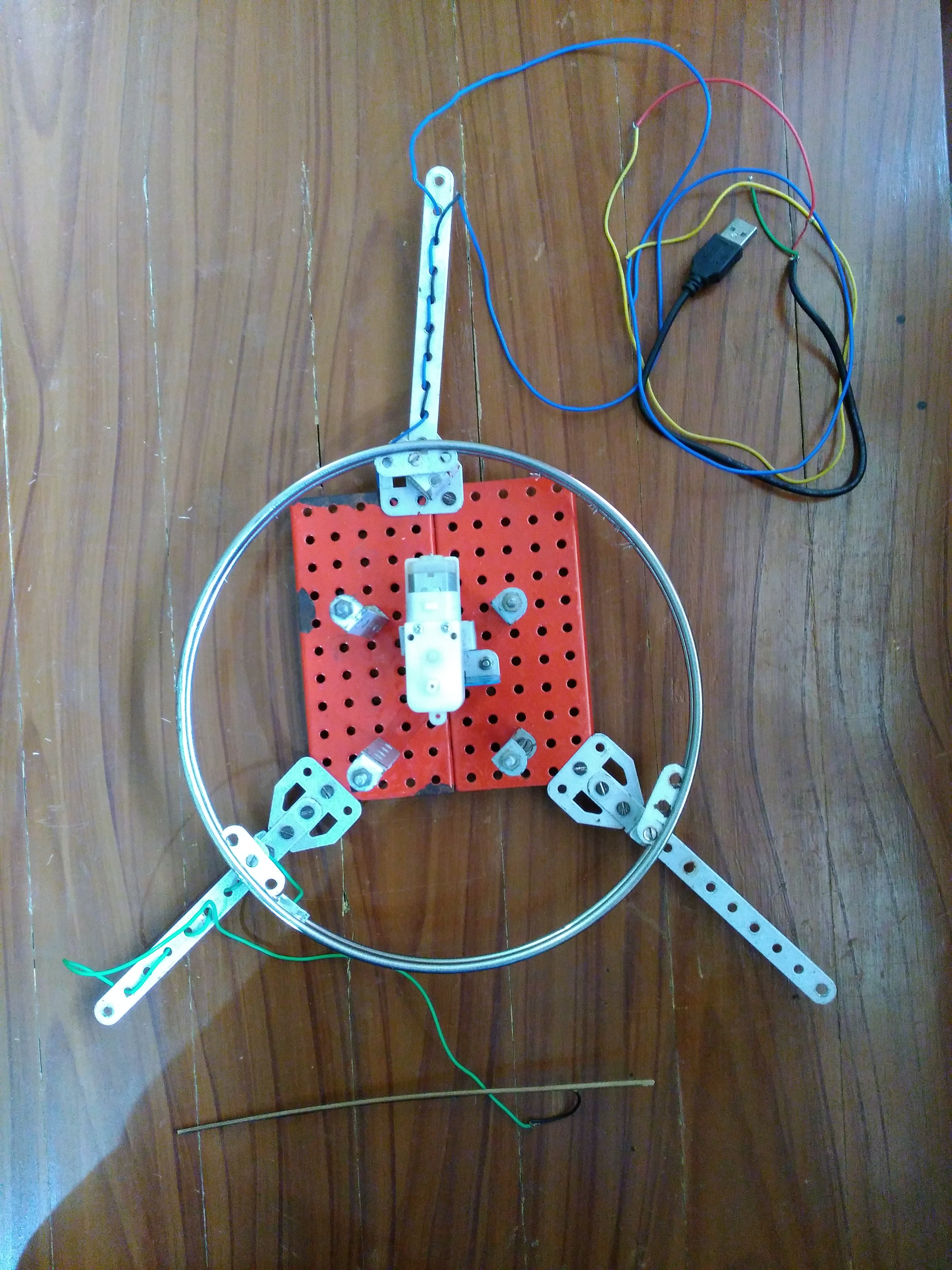
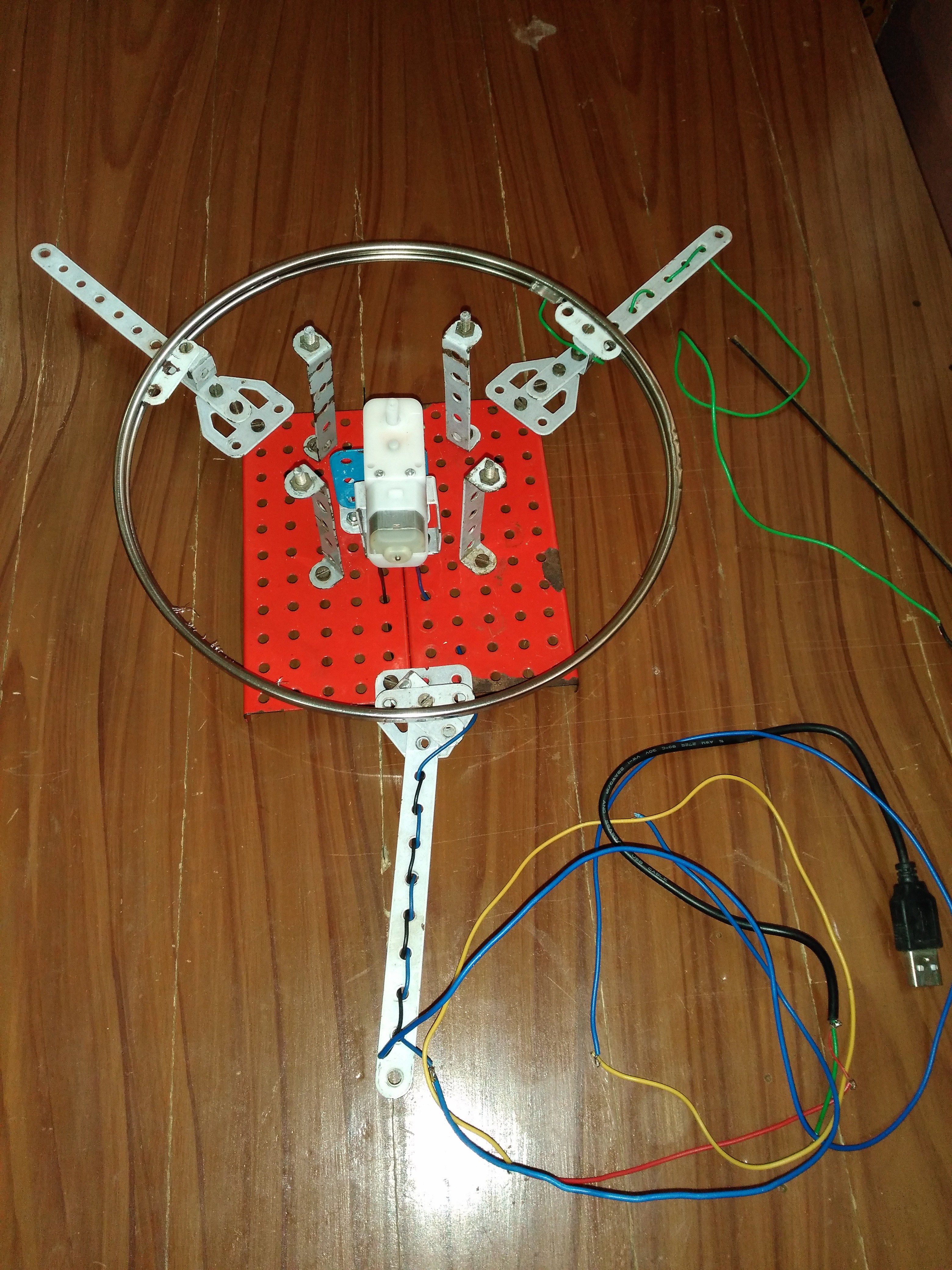
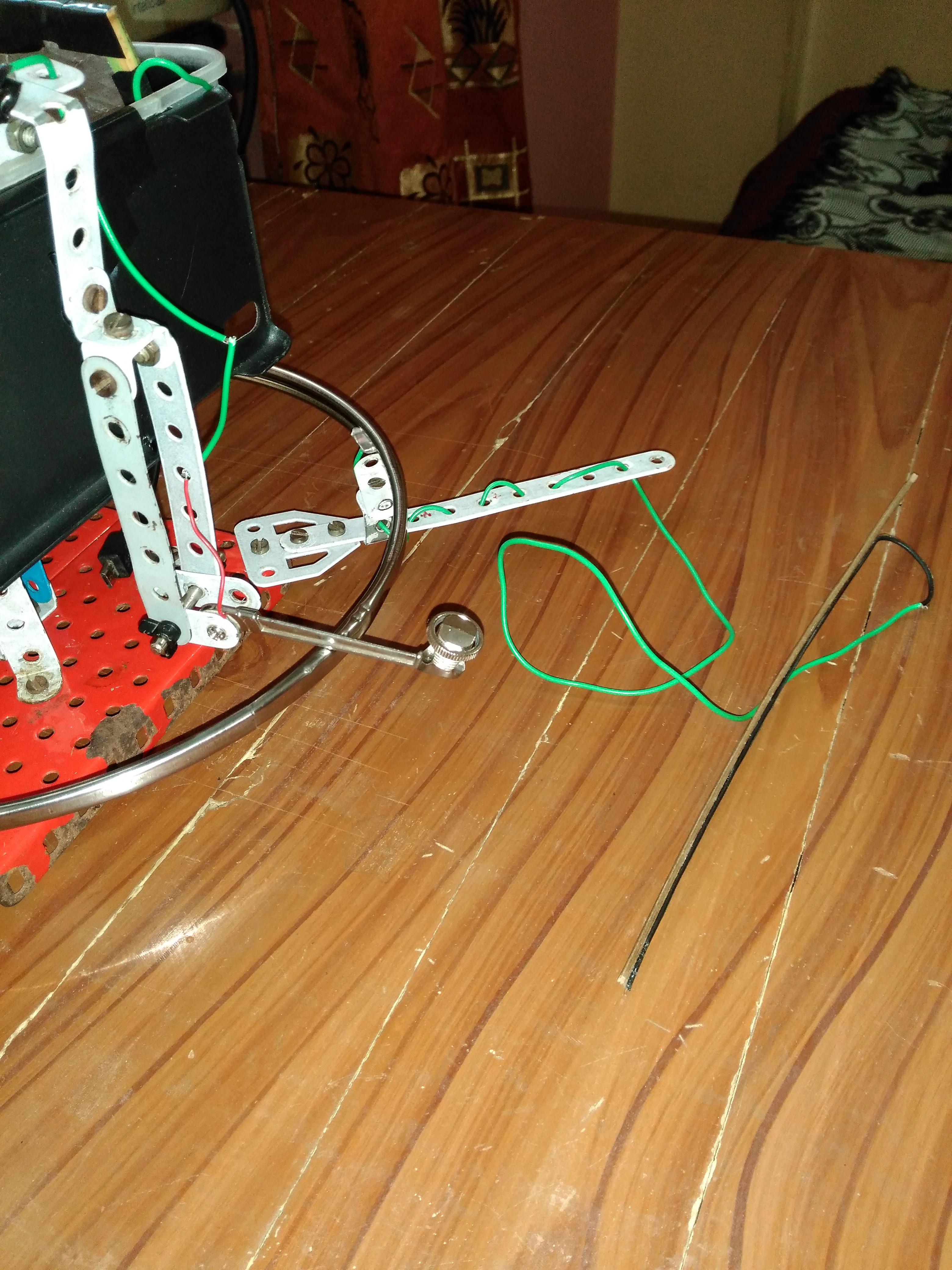
A metallic ring is fixed to the base of the sensor using clamps. A sliding metallic bar is attached to the rotating sensor to slide on this metallic ring. Connect the sliding bar to pin A0 of Arduino Uno. Connect the metallic ring to stylus wire.
- Assemble the Components
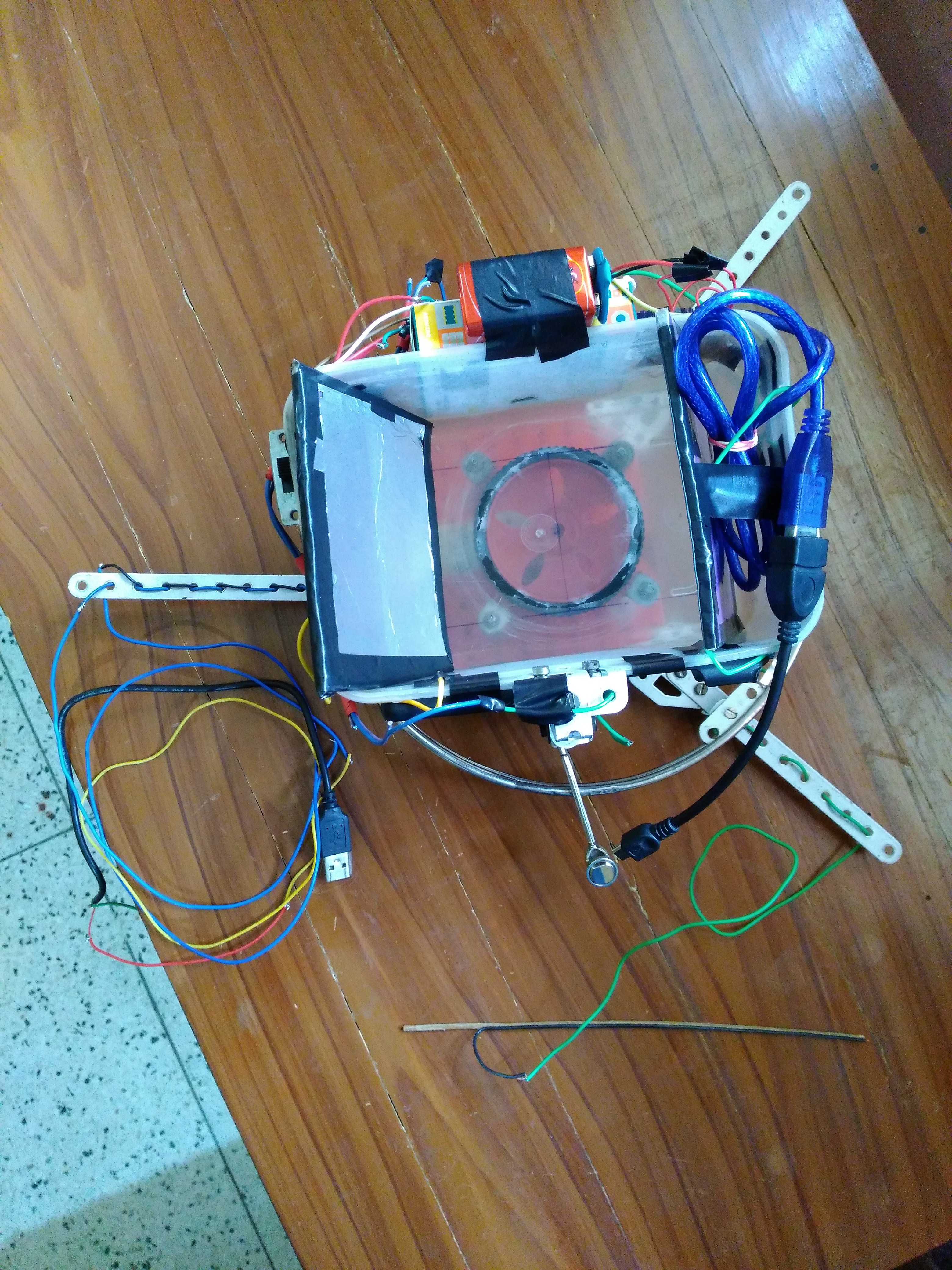
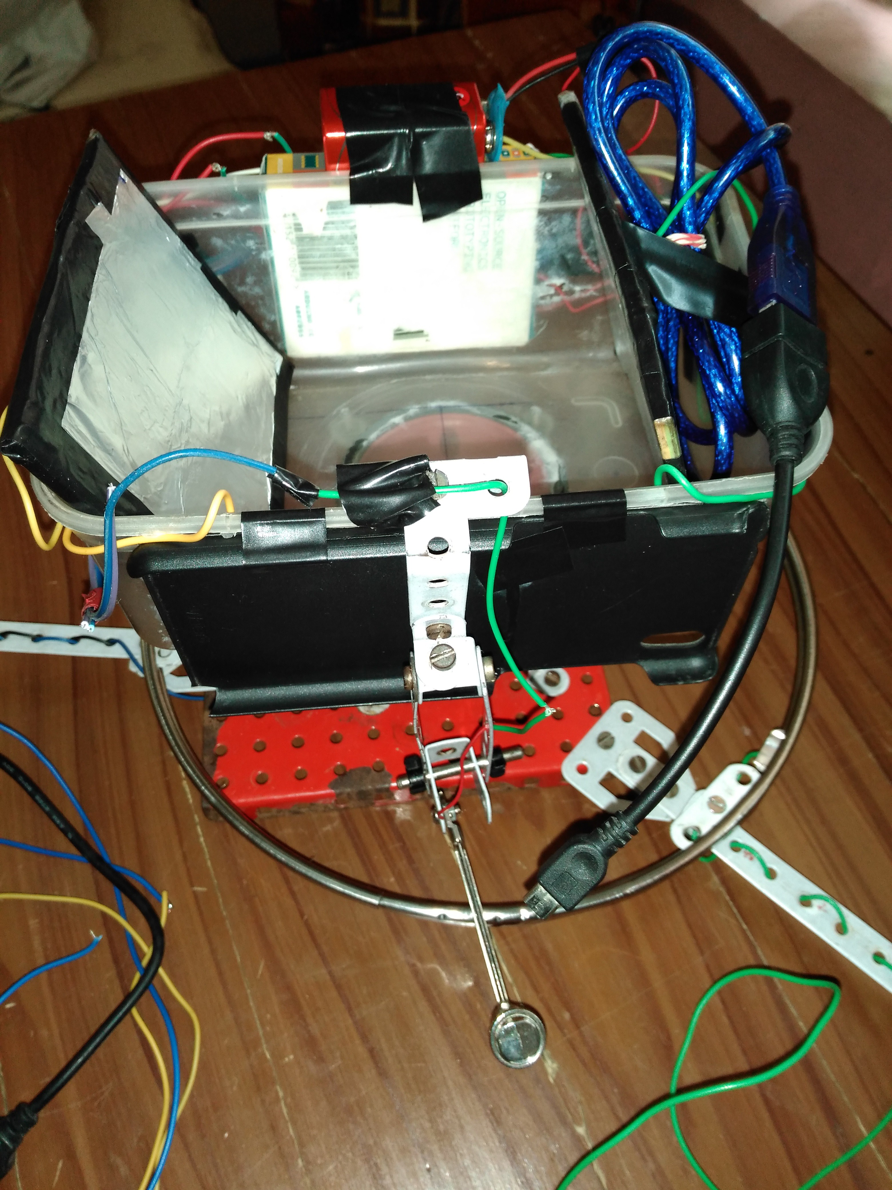

Attach the Arduino Uno on the lower face of the plastic water container box. Now fix this box on a plastic gear motor such that the axis of rotation is perpendicular to the horizontal base and passes through the intersection of the diagonals of the horizontal base of the parallelopiped formed by the electrode plates (diagonals of the parallelopiped base and not of the container base). Power the gear motor with a 5V 2A AC-DC power adapter.
Wipe the 2 aluminum electrodes and the interior of the plastic water container with a wet cloth to clean it of dust and impurities. Fill the water container with water from your home water purifier The water must be at room temperature. Salt or any other substances/impurities must NOT be added to it.
Measure the RPM of the plastic gear motor. Convert the angular velocity of the motor from RPM units to radians per second units and replace this value with the default value of the ANGULAR_VELO constant in the Arduino C++ code in 3d_sensor.ino. Move the stylus slowly in water to minimize ripples and disturbances in the water.


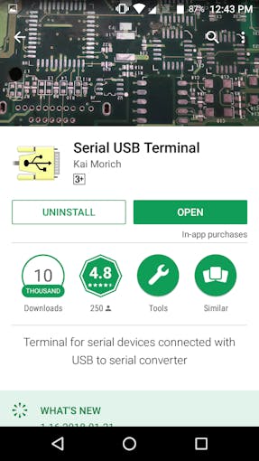
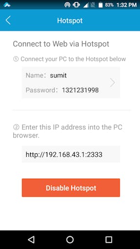
- Install 2 Android Apps
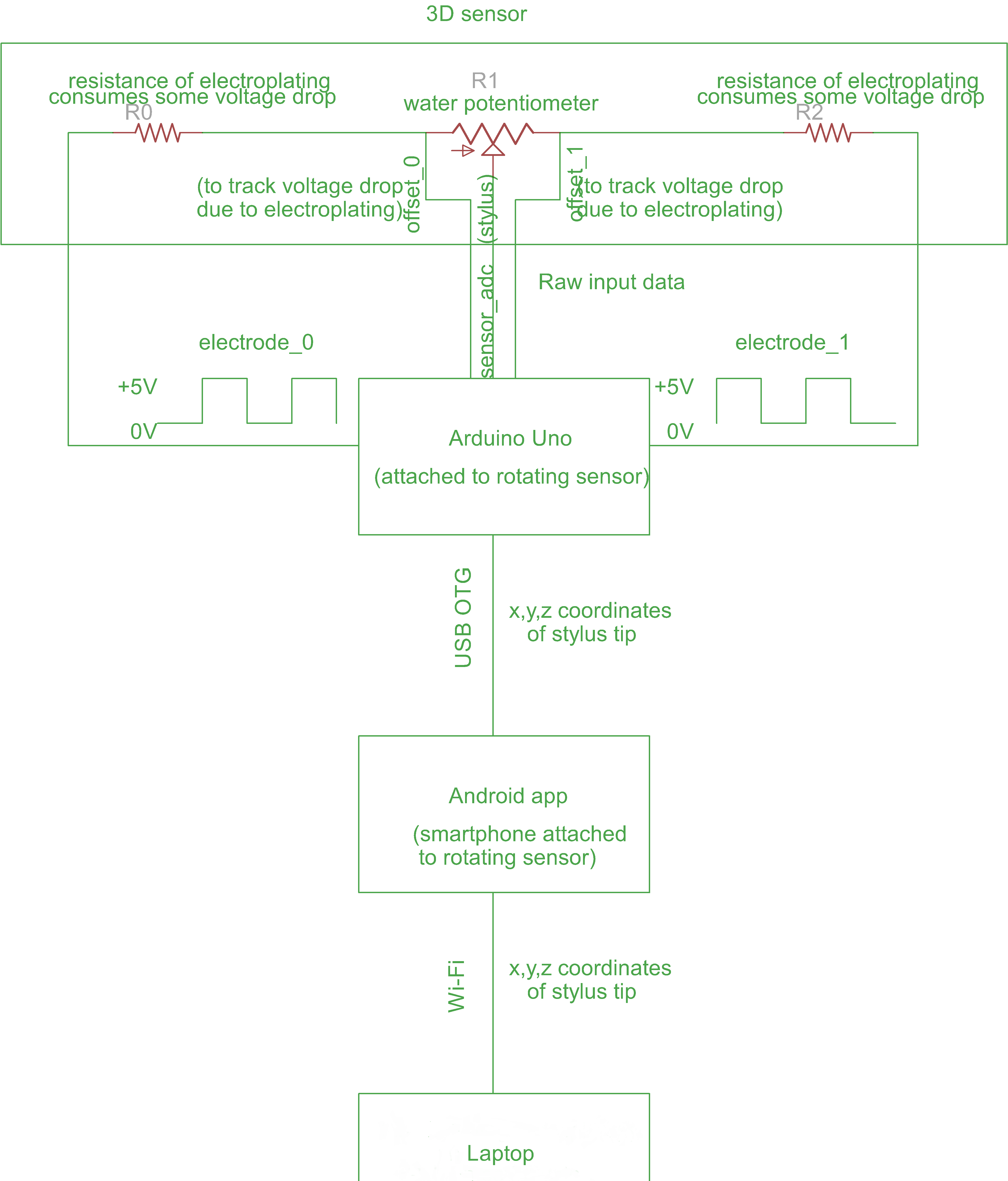
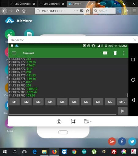
Arduino Uno, then, prints these x, y and z coordinates to the Serial USB Terminal Android App, serially, via USB OTG. The Android smartphone is attached to the rotating sensor, along with Arduino Uno. Connect it to Arduino Uno via a USB OTG cable. The AirMore Android App then casts the Android screen to Mozilla Firefox browser running on my laptop, via the phone’s WiFi Hotspot.
The format of serial output from Arduino Uno is as follows –
258
<x>
<y>
<z>
DATATYPE: x, y, z are all in float.
BAUDRATE: 115200 bits per sec
RANGE:
-128.00 <= x <= +127.00
-128.00 <= y <= +127.00
0.00 <= z <= +255.00
When the tip of the stylus is removed from water, only then, x=y=z= +257.00
258 is the code for “start of coordinates“.


5 Comments