- makeITcircular 2024 content launched – Part of Maker Faire Rome 2024Posted 2 weeks ago
- Application For Maker Faire Rome 2024: Deadline June 20thPosted 2 months ago
- Building a 3D Digital Clock with ArduinoPosted 7 months ago
- Creating a controller for Minecraft with realistic body movements using ArduinoPosted 7 months ago
- Snowflake with ArduinoPosted 8 months ago
- Holographic Christmas TreePosted 8 months ago
- Segstick: Build Your Own Self-Balancing Vehicle in Just 2 Days with ArduinoPosted 8 months ago
- ZSWatch: An Open-Source Smartwatch Project Based on the Zephyr Operating SystemPosted 9 months ago
- What is IoT and which devices to usePosted 9 months ago
- Maker Faire Rome Unveils Thrilling “Padel Smash Future” Pavilion for Sports EnthusiastsPosted 10 months ago
DIY Battery Powered USB Travel Charger
Web site:
http://www.electro-labs.comProject Summary:
Battery powered devices are all around us in daily life and we always face with low charge problems which lets us down in the middle of the day. Especially phones, music and video players, e-book readers etc. Sometimes we can’t find a mains source to plug an AC adapter or an USB port of a computer. In those cases, the battery powered USB travel charger comes to aid. It can be powered by two or three AA or AAA size batteries which you can find easily or carry with you while you are mobile.
Full Project:

This article provides all the steps of the design and the manufacturing process of DIY Battery Powered USB Travel Charger project. We will draw the circuit, and the PCB by using SoloPCB tools which are free and powerful to cover all our needs. When we finish the board, we will get the PCBs manufactured by Mass Design which has an ordering system integrated to SoloPCB. After receiving the bare boards, we will solder the components, power the circuit up and finally share the test & performance results.
Circuit Design:
There are various types of batteries in the market. The main two categories are primary (non-rechargeable) and secondary (rechargeable) batteries. Non-rechargeable batteries are also called “Single-Use” or “Throw-Away” since they cannot be used or recharged after they run empty. They are mainly categorized as Carbon-Zinc, Alkaline and Lithium depending on their internal chemical structure. Rechargeable batteries as their name implies, they can be recharged for reuse. The types of this kind are Rechargeable Alkaline, Nickel-Cadmium (Ni-Cd), Nickel-Metal Hydride (MiMH), Lithium Ion and Lead Acid. All those batteries have different output voltages which range from 1.2Vdc to 1.5Vdc.
To power our charger, we will use two NiMH rechargeable batteries in series which will results 2.4Vdc. Since we will make a USB charger, we need to get 5Vdc and 500mA output from the circuit. This means we need a DC-DC Step-Up converter which will convert 2.4Vdc to 5Vdc and which is capable of supplying 500mA continuously. When we search for the products of Step-Up converter IC manufacturers, we see that LT1302-5 from Linear Technologies best suits to our needs. The main features of this Fixed 5V DC/DC Converter IC are;
- 5V at 600mA from 2-Cell Supply
- 200uA Quiescent Current
- Logic Controlled Shutdown to 15mA
- Low VCESAT Switch: 310mV at 2A Typical
- Burst Mode Operation at Light Load Current Mode Operation for Excellent
- Line and Load Transient Response
- Available in 8-Lead SO or PDIP
- Operates with Supply Voltage as Low as 2V
LT1302-5 seems like it is already designed for our purpose. So the main component of the charger will be LT1302-5. The datasheet of LT1302-5 provides a reference design for two cell powered and 5Vdc-600mA generating application. We will use that design.
We need a software to draw the circuit and since we will draw the PCB in the further steps, the schematic and PCB software should be fully integrated. SoloPCB tool is one of the best free solution for this purpose. You can download it for free at FabStream.com.
Before starting to draw the schematic, we need to have all the necessary parts in the schematic symbol libraries. But it is not always possible to find all the components in the existing libraries. So we need to draw the missing parts. SoloCapture provides a part editor to draw and edit a custom part. When we search for LT1302-5 in SoloCapture libraries, we couldn’t find it. So we need to draw it from scratch. SoloCapture’s part editor provides us a flexible and easy to use interface to create a new part. In the following video tutorial, we will draw LT1302-5 from scratch. You can watch this example and learn the basics of this part creation process. Anyway, the schematic library for this project including all the necessary parts is also downloadable in the project archive.
Download the SoloPCB Design Files – DIY Battery Powered USB Travel Charger
In the following tutorial, we will show you how to create a custom schematic symbol in SoloCapture. Creating a new library, drawing the part outline, adding pins, assigning the pin and part properties are explained in detail.
Now we can create any type of schematic symbol in SoloCapture. After we have all the necessary parts, we can start drawing the whole schematic. In the following video tutorial, we will show you how to draw a schematic in SoloCapture. The schematic we will draw is also shown below.

Figure 1 – Schematic of DIY Battery Powered USB Travel Charger
PCB Design:
We have the schematic already drawn in SoloCapture. Now we will use SoloPCB to draw its PCB. Since both tools are fully integrated, all the components and the nets will be mapped to SoloPCB and we will be able draw the PCB synchronized to the schematic which will make the PCB error free.
In the PCB side, we need the footprints of all the components used in the schematic. SoloPCB provides almost all of the footprints we use. Anyway, it will be good practice to create a custom footprint from scratch. In the following tutorial, we will show you how to create a custom PCB footprint in SoloPCB. Creating a new footprint library, drawing the part outline, adding pads and setting the coordinates of them, assigning the pad properties, using the footprint wizard are explained in detail. On the other hand you can find the project footprint library including all the necessary footprints created for this project from in the project archive.
Download the SoloPCB Design Files – DIY Battery Powered USB Travel Charger
Now we can draw the whole PCB. In the following tutorial, drawing process is shown in detail.
PCB Manufacturing
After finishing the PCB, we placed our order via SoloPCB software and get the PCBs in two weeks.

Figure 2 – Bare Boards Manufactured by Mass Design PCB
The bare PCB boards look great. The manufacturing quality is quite high. Now we can solder the components and power the board up.
Assembly and Test:
The part list is given below. They are all SMD components so you need to have intermediate level of soldering skill. You can easily find and order the components from Farnell, Digikey, Mouser etc. At DealExtreme you can find various battery holders such as 2xAA, 3xAA, 2xAAA, 3xAAA, with cover or without cover, with switch or without switch etc. It should be better if you have a battery holder with switch, but if you don’t, no problem since the quiescent current of the circuit is extremely low which is about 200 micro amps.
Part List
- 1 x LT1302-5 Fixed 5V DC/DC Step-Up Converter
- 1 x MBRS130LT3G Schottky Diode
- 1 x MSS1260-103ML 10uH 3A Power Inductor
- 2 x 100uF 10V C or D-Case Tantalum Capacitor
- 1 x 0.1uF 63V 0805 Case Ceramic Capacitor
- 1 x 0.01uF 63V 0805 Case Ceramic Capacitor
- 1 x 20K up to %10 0805 Case Resistor
- 2 x 75K up to %10 0805 Case Resistor
- 2 x 50K up to %10 0805 Case Resistor
- 1 x 2xAA, 2xAAA, 3xAA, 3xAAA Battery Holder
The assembled circuit board is shown below,

Figure 3 – Assembled Circuit – Front View

Figure 4 – Assembled Circuit – Back View
It is time to test the board. We need two AA size batteries since the battery holder is 2xAA. In this step, we used two different batteries. GP 2700 Series 2600 mAh rechargeable battery and Duracell MN1500 Alkaline non-rechargeable battery.
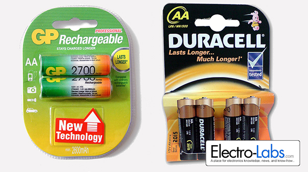
Figure 5 – Gp-2700 Series 2600mAh rechargeable batteries
Fully charged GP 2700 batteries could charge 85% of iPhone 3GS’s internal battery. And Duracell MN1500 batteries could charge only 20% of the same battery.
Fully charged GP 2700 batteries could charge 90% of LG Optimus E420-II. And Duracell batteries could charge 25% of the same battery.

Figure 6 – Charging LG Optimus E420-II
Fully charged GP 2700 batteries could charge 100% of the battery of Amazon Kindle twice. And Duracell batteries could charge 50% of the same battery.

Figure 7 – Charging Amazon Kindle
Considering the test results, it is obvious that we should use rechargeable batteries to be able to get a significant charge percentage.The capacity of those rechargeable batteries also plays an important role. On the other hand, the circuit lets an input voltage less 5Vdc. So we can use 3xAA or 3xAAA batteries which provide 1.2V nominal output voltage. This time we will need a larger battery holder.

-
 Arduino ISP (In System Programming) and stand-alone circuits
We use an Arduino to program other ATmega without...
- Posted 12 years ago
-

-

-
 GSM GPS shield for Arduino
Shield for Arduino designed and based on the module...
- Posted 12 years ago
-
 Small Breakout for SIM900 GSM Module
Some post ago we presented a PCB to mount...
- Posted 13 years ago
-
 makeITcircular 2024 content launched – Part of Maker Faire Rome 2024
Applications to MakeITcircular must be in by October 3,...
- Posted 2 weeks ago
-
 SONY color camera module, 700 TV Lines
Color camera module equipped with a 1/3″ CCD sensor...
- Posted 3 weeks ago
-
 ESP32 Low Power Module
ESP32 Low Power Module, based on Espressif’s SoC capable...
- Posted 2 months ago
-

-
 Application For Maker Faire Rome 2024: Deadline June 20th
Learn More About the Ideas, Makers + Projects at...
- Posted 2 months ago
2 Comments