- makeITcircular 2024 content launched – Part of Maker Faire Rome 2024Posted 2 weeks ago
- Application For Maker Faire Rome 2024: Deadline June 20thPosted 2 months ago
- Building a 3D Digital Clock with ArduinoPosted 7 months ago
- Creating a controller for Minecraft with realistic body movements using ArduinoPosted 7 months ago
- Snowflake with ArduinoPosted 8 months ago
- Holographic Christmas TreePosted 8 months ago
- Segstick: Build Your Own Self-Balancing Vehicle in Just 2 Days with ArduinoPosted 8 months ago
- ZSWatch: An Open-Source Smartwatch Project Based on the Zephyr Operating SystemPosted 9 months ago
- What is IoT and which devices to usePosted 9 months ago
- Maker Faire Rome Unveils Thrilling “Padel Smash Future” Pavilion for Sports EnthusiastsPosted 10 months ago
Automatic TEST BENCH
Web site:
http://kll.engineering-news.org/kllfusion01/articles.php?article_id=51Project Summary:
Use an arduino
- to set 2 parameter X ( dout PWM D5 ) and Y ( dout PWM D6 )
- to set 1 parameter N ( dout D7 ON / OFF )
and measure the result Z ( with Ain0 )
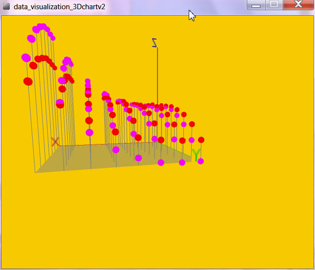
The measuring data field store to CSV and visualize it with processing
as 2 sets of 3D data.
Full Project:
Using this software with a arduino UNO and drive the in CIRCUIT DIAGRAM shown hardware allows to measure Z as 2 * 64 points ( with X,Y in steps 0 .. 7 ) sample time and settling time adjustable, min whole batch 1.28 sec. up to 4days?
Operation can be on arduino USB menu or processing keyboard commands:
(1) measure batch
(2) retrieve data to CSV file
(r) set data file active and show as 3.5D graph.
when the data are collected, and saved as CSV file, the processing tool can show the 2 datafields.

the visualization is adjustable by mouse ( rotate, zoom ) and by keyboard if you need to show the
– groundfloor
– BARs
– DOTs
– AREAs
But there also is a manual operation possible, via arduino menu or processing keyboard commands a setpoint N,X,Y, timer(millis) can be selected, [3] [0/1] [0..100] [0..100] [1000]
and a conti measurement [4] can be started and from there a incremental setpoint change is possible by [n] [N] [x] [X] [y] [Y] == down UP of the 3 outputs / axis.
For this the Z value is show in diagnostic window only.
In the revision from http://kll.engineering-news.org/kllfusion01/downloads.php?cat_id=2&download_id=30 [5] the X is hold HIGH and the Y is performing a PWM signal SINUS [100] (loopcycles) to adjust a frequency
what via a 10uFcapacitor is generating a real analog signal ( medium quality ).
pls read more details at my BLOG
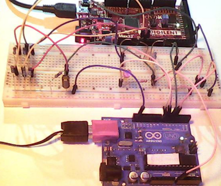
Circuit diagram:
The arduino controls your test bench, i used for development just a easy RC circuit and measured the voltage ( range ) the 2 PWM outputs created.
That is my reference data set. For the test signal i use the N ( Dout D7) to discharge that voltage via resistor and LED.


Bill of Materials:
arduino UNO
your test bench or
above circuit for test signal generation.
1 * LED
1 * R 220ohm
2 * R 1Kohm
1 * R 470ohm
1 * C 1 .. 10 uF
Firmware:
using arduino IDE 1.5.3 ==1.0.5 beta 3
and processing 2.0.3
here my code for arduino and processing

-
 Arduino ISP (In System Programming) and stand-alone circuits
We use an Arduino to program other ATmega without...
- Posted 12 years ago
-

-

-
 GSM GPS shield for Arduino
Shield for Arduino designed and based on the module...
- Posted 12 years ago
-
 Small Breakout for SIM900 GSM Module
Some post ago we presented a PCB to mount...
- Posted 13 years ago
-
 makeITcircular 2024 content launched – Part of Maker Faire Rome 2024
Applications to MakeITcircular must be in by October 3,...
- Posted 2 weeks ago
-
 SONY color camera module, 700 TV Lines
Color camera module equipped with a 1/3″ CCD sensor...
- Posted 3 weeks ago
-
 ESP32 Low Power Module
ESP32 Low Power Module, based on Espressif’s SoC capable...
- Posted 2 months ago
-

-
 Application For Maker Faire Rome 2024: Deadline June 20th
Learn More About the Ideas, Makers + Projects at...
- Posted 2 months ago