
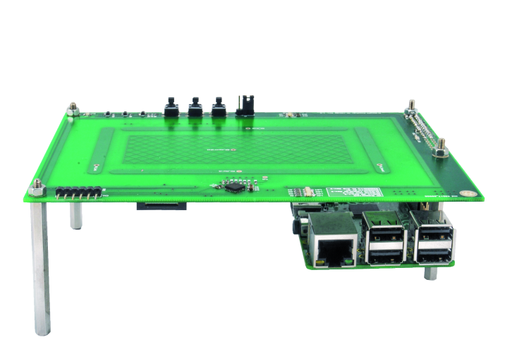
Let’s couple the 3D gesture recognition electrode to Raspberry Pi, in order to create an application with which the pictures can be scrolled on a HDMI screen, by means of gestures.
In the previous post we described a new GestIC electrode, which has been developed and created for the purpose of interfacing the Arduino Uno Rev. 3, Arduino Leonardo Rev. 3 and Raspberry Pi B+/2.0 boards, and we proposed an application for Arduino. We also promised that we would propose the coupling with Raspberry Pi in a short time; and well, the time has come to see the interfacing with this board and to analyze the implementation of the library, which is needed to manage the MGC3130 integrated circuit. The library has been written in Python, that is to say a dynamic programming language, directed to items, and that can be used for any kind of software development. Moreover it allows developing quality code that can be easily maintained, it offers a strong support to integration with other languages and programs, it is provided with an extended standard library, and can be learned in a few days (at least as regards its basic functions).

How to configure Raspberry Pi
Before delving deeper into the description of Python’s library, it is needed to carry out some intermediate steps to configure Raspberry Pi. Let’s see how to proceed, step by step: as a first thing, it is needed to install the Python library for the Raspberry Pi’s I/O management and, if it’s already installed, to update it to the latest available release, at the moment being 0.5.11.
To verify the current GPIO library’s version, please execute the following command:
find /usr | grep -i gpio
In figure, highlights the feedback to the command sent; in this case it turns out that it is updated to the latest release. If the library’s release precedes 0.5.11, please update it by means of the following command:
sudo apt-get update
sudo apt-get upgrade
or use the following ones:
sudo apt-get install python-rpi.gpio
sudo apt-get install python3-rpi.gpio

Now, let’s move onto the configuration of the I2C peripheral, made available by Raspberry Pi; let’s proceed with the installation of the Python “smbus” Python library for the management of the I2C bus:
sudo apt-get install python-smbus
to be followed by the I2C tools:
sudo apt-get install i2c-tools
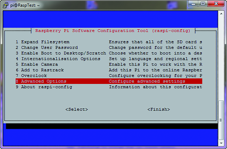
We will then have to enable the I2C bus support on the part of the kernel; to do so it is needed to recall the configuration window, by typing in the following command:
sudo raspi-config
As it can be seen in figure, let’s select the “Advanced Options” entry, and then:
– in the new screen, let’s select the “A7 I2C Enable/Disable automatic loading” entry, as in figure;

– in the following screens, we will have to answer, in sequence: “Yes”, “Ok”, “Yes” and finally “Ok” again;
– let’s exit the configuration window by choosing the “Finish” entry.
Let’s execute now the system reboot by executing the command:
sudo reboot
After having rebooted Raspberry Pi, let’s open the “modules” file with a generic text editor, by means of the command:
sudo nano /etc/modules
At this stage we will have to add, if they are missing, the two following lines:
i2c-bcm2708
i2c-dev

Finally, it is needed to verify if in your distribution there is the following file:
/etc/modprobe.d/raspi-blacklist.conf
If so, please open it with a text editor by using the following command:
sudo nano /etc/modprobe.d/raspi-blacklist.conf
and, if they are found, please comment (by using the “#” character) the following instructions:
blacklist spi-bcm2708
blacklist i2c-bcm2708
At this stage, there is nothing else to do but to reboot Raspberry Pi again, and to verify that the I2C communication is active; to do so please execute the following command:
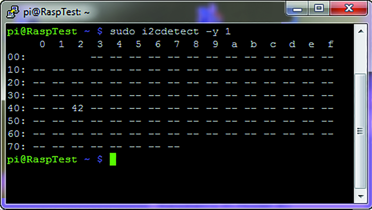
sudo i2cdetect -y 1
If everything reached a successful ending, the command sent will return a table as the one shown in figure. In practice, the command analyzes the I2C bus, looking for peripherals; and in our case it located the MGC3130 integrated circuit, having 0x42 as address.
The configuration for the I2C hardware and its relative management library is now complete; it is now needed to download and install a Python module that simulates the keyboard buttons pressure, so that it is possible to associate one gesture to a key, for example the function keys: F1, F2, etc.
The module to be downloaded can be found at the following link:
https://github.com/SavinaRoja/PyUserInput
Please download the .zip file and extract it in a directory: for example “home” or, if you prefer, in a directory purposely created by you.
Among the extracted files you will find one, named “Setup.py”, that you will need in order to install the module of your distribution and to make it available in Python’s path, so that it may be possible to include it in your own projects.
Thus please type in the following command:
python setup.py install
If all the dependences have been verified, the module will be installed and immediately made available, so that it may be integrated in your projects. It may happen, however, that not all the dependences are respected and that there is need to install the additional “pi3d” module, that can be downloaded here.
As for the previous one, please download, unpack and finally install it by typing in the following command:
python setup.py install
Finally, it could be needed to install the “xlib” library for Python, that can be installed by means of the following command:
sudo apt-get install python-xlib
Well, once arrived at this stage we have everything we need to introduce and study the management library of the MGC3130 integrated circuit, developed in Python.
MGC3130 and the library for Raspberry Pi
Let’s talk now about the library, written in Python and needed to manage the MGC3130 integrated circuit; it is made along the lines of the one we already presented for Arduino. Let’s start by specifying something on the subject of the data structures management in Python, that are needed to manage the data flow coming from the MGC3130 integrated circuit. In Python, the data structures are built in a way that is slightly different than if they were written in the C programming language: as follows we will thus refer a comparison between the data structure, written in C for Arduino, and the new library, written in Python for Raspberry Pi. As you will remember from the previous episode, the data structure used for Arduino is created in the way shown in Listing 1.
Listing 1

We will show now the corresponding one, as written in Python in Listing 2: you will notice that the formulation is different but the function carried out is the same one.
Listing 2
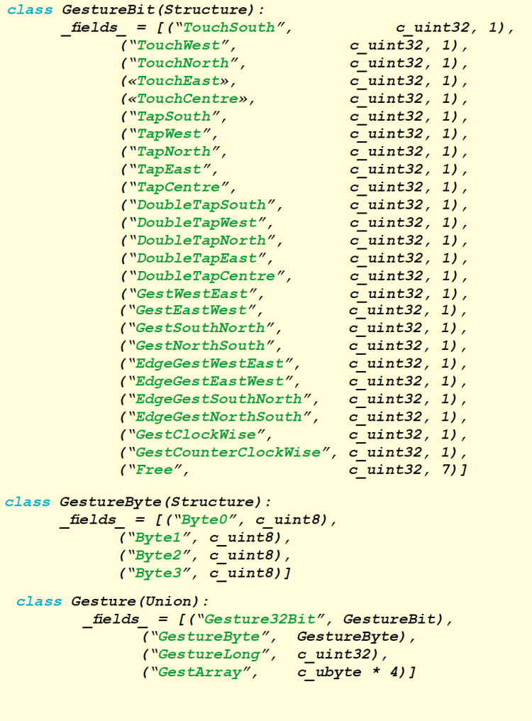
Even if they look different, they are actually the same and carry out the same task. In our case, to access this data structure it is needed to declare a variable in the Python file, one that recalls the said structure, for example:
_GestureOutput = Gesture()
Such a declaration can be carried out as a global type, and thus it can be seen at each declared function in the library file, provided that in each function the following line is declared:
global _GestureOutput
in doing so we indicate to the Python interpreter that the variable is of the global type. To access the value of the Tap gesture on the South electrode, for example, we have to write the following code line:
if (_GestureOutput.Gesture32Bit.TapSouth):
If on the other hand we want to set the value of the said bit, we have to use the following syntax:
_GestureOutput.Gesture32Bit.TapSouth = 0
In addition to the bit level, it is possible to access the data at the level of the single byte, for a total of four bytes (32 total bits, of which seven are free for future developments); or directly as double word, by operating all at once on all the 32 bits of the structure. Thus the access becomes:
_GestureOutput.GestureByte.Byte0 = 0x00
_GestureOutput.GestureLong = 0x00000000
After this premise, let’s analyze the functions made available by our library; in particular, we have the following public functions:
def MGC3130_SetAdd(Addr)
def MGC3130_ResetDevice(GPIO, Rst):
def MGC3130_ExitResetDevice(GPIO, Rst):
def MGC3130_Begin(GPIO, Ts, Rst):
def MGC3130_GetTsLineStatus(GPIO, Ts):
def MGC3130_ReleaseTsLine(GPIO, Ts):
def MGC3130_GetEvent():
def MGC3130_DecodeGesture():
The “MGC3130_SetAdd” function is needed to set the hardware address that is occupied on the I2C bus by MGC3130, in our case it is exclusively 0x42, in any case. The only parameter to give to this function is indeed the hardware address.
The “MGC3130_ResetDevice” function, as hinted by the name, is needed to keep the MGC3130 integrated circuit in a reset condition, as long as the condition itself is not removed. There are two parameters to give: the first one is the GPIO library needed to manage the generic I/O lines, while the second one is the pin associated to the RESET line.
The opposite function is the “MGC3130_ExitResetDevice” one, which removes the RESET condition; the parameters to give are the same of the previous function.
The “MGC3130_Begin” function is needed to initialize the communication lines between Raspberry Pi and the MGC3130. The parameters to give to the function are the GPIO library, the pin number for the TS line and the pin line for the RESET line.
The TS pin is set as an input, with the internal pull-up resistor enabled, while the RESET line is set as an output with high logical value. The initialization takes into account that the integrated circuit will be kept in a forced RESET condition for a period of 250mSec, so to bring it to the starting conditions, as if a power-up happened.
The “MGC3130_GetTsLineStatus” function is needed to monitor the TS line and to intercept the moment when the MGC3130 integrated circuit keeps it busy, so to inform that a gesture has been recognized. As soon as the system realizes that the TS line has been kept busy, it changes the pin state by going itself to occupy the TS line, so to start the reading process of the data contained in the MGC3130’s buffer. Once the data reading has been ended, the “MGC3130_ReleaseTsLine” function can be recalled, so to release the TS line.
For both the functions we just described, we need to give two parameters: the first one is the GPIO library, while the second is the pin to which the TS line is connected.
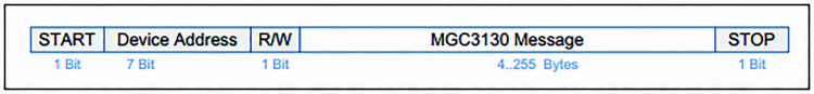
The “MGC3130_GetEvent” function is needed to read the data that has been memorized in the MGC3130’s buffer, and to save it in dedicated data structures used by the library. A following function will be then the one to decode all of the data received and to make it available for the final user and his application. We would like to remind you, as we already did in the previous episodes, that the data package used for the reading of the data loaded in the MGC3130’s buffer is of the kind shown in figure.
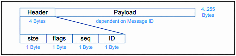
The address contained in the package is the one of the integrated circuit’s hardware: the less relevant bit indicates if we are in writing (“0”) or reading mode (“1”). The “MGC3130 message” section may be extended, as indicated in figure, so to identify two sections: “Header” and “Payload”.
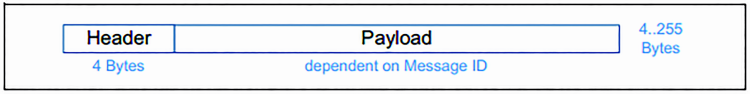
By further expanding the “Header” section, as shown in next figure, it is possible to notice that in the first four bytes we find the length of the data package received and, a very important thing, the ID that identifies the data package. In the case of a data reading after the recognition of a gesture, the ID package will be 0x91. For a listing of the ID codes that are available, we invite you to read the previous episode.
The library manages the 0x83 ID as well, that identifies the library review, loaded within the integrated circuit. This information is read at the start-up, after having removed the RESET condition. At the moment there is a limit for the bytes that can be read by the I2C bus, when using of the “smbus” library, in other words the maximum length for the library’s receiving buffer is set to 32 bytes, which can be a bit constraining. This implies that the data package having 0x83 as an ID, and read by the MG3130’s buffer, is cut off. For those who would like to test themselves, it is possible to download the “smbus” source library, to change the buffer’s length, to recompile and install again the library in their own distribution.
The “MGC3130_GetEvent” function applies some filters to the data read by the MGC3130’s buffer, so to eliminate the parts that are not needed for our purposes. The essential data is the one concerning the “GestureInfo” and the “TouchInfo”, to which the bit mask is applied, in order to eliminate the unwanted bits (the “MASK_GESTURE_RAW” is applied to the “GestureInfo” while the “MASK_TOUCH_RAW” is applied to “TouchInfo”). The user should never modify these values, unless he has some valid reasons.
“MGC3130_DecodeGesture”, the last function, decodes the data read by the previous function and makes it available by means of a public data structure, that the user may use for his application (please see the previously described data structure). The library realizes the changes that have been caught by the MGC3130 integrated circuit, and returns them on the corresponding bits of the public data structure. The gesture is recognized when the corresponding bit goes to the logical level “1”. If so desired (but it is not mandatory), it is possible to filter the gestures we do not want to use in our project. In fact, it is possible to configure a bit mask, that can be found in the MGC3130_DefVar.py file, that allows to filter the unwanted gestures. The constant is named “MASK_FILTER_GESTURE” and is a 32 bit value that can be configured, bit by bit. If the bit is at logical level “1”, it means that we wish to filter the gesture, vice versa we want to keep it.
To promote the study of the library, there are hidden code parts that can be activated or deactivated, by means of especially declared boolean data types. If the value is “True”, it activates the affected code part, otherwise it turns it off. The data types are the following ones:
1) EnablePrintMGC3130RawFirmwareInfo = False
2) EnablePrintMGC3130RawData = False
3) EnablePrintMGC3130Gesture = False
4) EnablePrintMGC3130xyz = False
Given the default settings, the data types are all set to the “False” value; if activated, you will see that the data read by the integrated circuit will be printed on screen, and possibly along with the corresponding decoding. In particular we have, in order:
1) Printing of the data concerning the FW revision loaded in the integrated circuit, in RAW format
2) Printing of the data concerning the recognized gesture, in RAW format
3) Printing of the recognized gesture after the decoding
4) Printing of the x, y and z coordinates
For example, if the “EnablePrintMGC3130RawData” boolean data type is set to the “True” value, catching the “Flick East to West“ gesture will generate a data table, with such a format:
##############################################
Row data from MGC3130
Header: 1A081191
Payload: 1F01 | 86 | 80 | 0073 | 03100000 | 00000000 | 0000 | 000000000000
##############################################
To increase its readability and help to understand it, the data package is divided between “Header” and “Payload”, moreover the “Payload” is divided in sub-packages (please see the GestIC library’s datasheet).
MGC3130 Demo
Let’s describe now our demo program (still written in Python), that gives us the chance to directly manage an image viewer software, by means of the gestures that are recognized by MGC3130. The program is named “Eye Of Gnome” and can be installed on your own Raspberry Pi, simply by executing in the following command:
sudo apt-get install eog
We will analyze now the demo created for Raspberry Pi, the file is named “DemoGestic.py”, and as for all the files written in Python, the declarations concerning the importation of the modules needed for its proper functioning are found ahead. Among them we will find our library, needed for the management of the MGC3130 integrated circuit (import MGC3130), the library for the I/O management (import Rpi.GPIO), a library for the Threads management (import threading), a library for the times management (import time) and finally a keyboard buttons emulation library (from pykeyboard import PyKeyboard).
To make it easier to manage the code, the constant variables are declared: they identify Raspberry Pi’s I/O pins. In particular, there are the TS and RESET lines, as well as the SDA and SCL lines, the buttons, the jumper and the diagnostics LED. All of these definitions come in handy when configuring the I/O pins to be used with Raspberry Pi and all of the times we want to test their value or to modify their state.
As it can be noticed from Listing 3, with the “setup” function it can be defined if the pin we’re interested in is an input or an output one and, in the case of input pins, the internal pull-up resistors are activated. Moreover, for the P1, P2 and P3 input buttons a further parameter is defined: it introduces the event management for the button being pressed, “add_event_detect”, which intervenes in the descent fronts with a debouncing time of 100mSec.
Listing 3

In the infinite main cycle there is, therefore, the management of the three buttons waiting for the above configured event to happen, for example:
if GPIO.event_detected(PULSE_P1):
This conditional instruction is waiting for the interception of the event concerning the P1 button being pressed, in order to execute its function. In particular, we defined that the P1 Button activates the demo and therefore enables the association of a gesture with a keyboard button, the P2 button deactivates what we just explained, while the P3 button closes the demo by freeing the I/O ports from the configurations made. Before entering a “while” infinite cycle, the code executes a series of configurations, among which the one concerning the hardware address that occupies the MGC3130 integrated circuit on the I2C bus, as well as the one concerning the initialization of the I/O lines needed to manage it. In this second case, the GPIO library is given as a parameter to the configuration function; it is in fact good that this library is declared in a single point only, and then possibly given to the functions needing it. The code section dealing with the detection of the change on the TS line, and thus to look after the reading of the MGC3130’s buffer, is the following one:
if (MGC3130.MGC3130_GetTsLineStatus(GPIO, MGC3130_TS_LINE) == True):
MGC3130.MGC3130_GetEvent()
MGC3130.MGC3130_DecodeGesture()
MGC3130.MGC3130_ReleaseTsLine(GPIO, MGC3130_TS_LINE)
By using the following library function:
def MGC3130_GetTsLineStatus(GPIO, Ts):
we test the TS line, waiting for it to go at a low logical level, to then keep it busy and to start the data reading procedure, by means of the following library function:
def MGC3130_GetEvent():
The decoding functions for the data read in order to extract the recognized gestures and the function needed to release the TS line are as follows:
def MGC3130_DecodeGesture():
def MGC3130_ReleaseTsLine(GPIO, Ts):
We will describe now the interaction between the recognized gestures and the “Eye Of Gnome” image viewer. Once the software has been started and the directory with the images to browse has been selected, it is possible to execute the following operations:
1) to scroll the pictures to the right, with the Flick West to East gesture; it emulates the “right arrow” key;
2) to scroll the pictures to the left, with the Flick East to West gesture ; it emulates the “left arrow” key;
3) to enlarge the picture (Zoom in), with the Touch North Electrode gesture; it emulates the “+” key;
4) to reduce the picture (Zoom out), with the Touch South Electrode gesture; it emulates the “–” key.
5) to view the picture in full screen mode, with the Touch Centre gesture; it emulates the “F5” key;
6) to rotate the picture clockwise, with the Clockwise gesture; it emulates the “CTRL + R” key combination;
7) to rotate the picture counterclockwise, with the Counter Clockwise gesture; it emulates the “SHIFT + CTRL + R” key combination;
8) when the picture is enlarged, it is possible to move it on screen by using the following gestures: Flick West to East, Flick East to West, Flick North to South e Flick South to North.
But how does our code manage to emulate the keyboard buttons? It does it via the “PyUserInput” library. Once this has been imported, by means of the following command:
import PyKeyboard
we have to create the item:
KeyPressed = PyKeyboard()
The item created can manage the following events:
– press_key(‘h’); the example emulates the “h” key being pressed;
– release_key(‘h’); the example emulates the “h” key being released. For each “press_key” event, a “release_key” event always mandatorily follows (unless the situation requires the button to be pressed for a given period of time);
– tap_key(‘h’); the example emulates a keyboard button being touched;
– type_string(‘hello’); the example emulates a string being sent.
Thanks to these items it is possible to emulate key combinations as well, to emulate “shift” + “ctrl”+ “M” we need to write the following code:
KeyPressed.press_key(KeyPressed.shift_key)
KeyPressed.press_key(KeyPressed.control_key)
KeyPressed.tap_key(‘M’)
KeyPressed.release_key(KeyPressed.control_key)
KeyPressed.release_key(KeyPressed.shift_key)
After this premise we may describe how we used this library for our purposes. For example, the recognition of the “West to East” gesture is associated to the right arrow key:
if (MGC3130._GestOutput.Gesture32Bit.GestWestEast == 1):
MGC3130._GestOutput.Gesture32Bit.GestWestEast = 0
GPIO.output(LED_DIAGNOSTIC, GPIO.LOW)
BaseTimeTimer = threading.Timer(1, SlowBaseTime)
BaseTimeTimer.start()
KeyPressed.tap_key(KeyPressed.right_key)
By emulating the right arrow key, the pictures are scrolled to the right. The corresponding result for scrolling the pictures to the left will be:
if (MGC3130._GestOutput.Gesture32Bit.GestEastWest == 1):
MGC3130._GestOutput.Gesture32Bit.GestEastWest = 0
GPIO.output(LED_DIAGNOSTIC, GPIO.LOW)
BaseTimeTimer = threading.Timer(1, SlowBaseTime)
BaseTimeTimer.start()
KeyPressed.tap_key(KeyPressed.left_key)
When a gesture is recognized, the LD8 LED flashes for a second. A Thread is created, therefore, and it will be activated and recalled after a second of time for each gesture being recognized. More in depth, when a gesture is recognized, the LD8 LED is turned on by using the following code line:
GPIO.output(LED_DIAGNOSTIC, GPIO.LOW)
Soon after that, there is the activation of the Thread that will deal with turning off the LD8 LED, after a second.
More precisely, the activation of the Thread is made by executing the following code:
BaseTimeTimer = threading.Timer(1, SlowBaseTime)
BaseTimeTimer.start()
The function recalled by the Thread is the following one:
def SlowBaseTime():
global BaseTimeTimer
GPIO.output(LED_DIAGNOSTIC, GPIO.HIGH)
aseTimeTimer.cancel()
This function turns off the LD8 LED and deletes the recalled Thread, so that it is possible to call it again for the next event.
With this, we ended describing our demo for the management of the electrode for the MGC3130 coupled with Raspberry Pi B+ or 2.0. Please remember that, in order to activate the interaction between the gestures and the library emulating the keyboard buttons, you have to press the P1 button; vice versa to deactivate it, please press P2.
A few words concerning “EOG” and our demo
In order to activate the previously installed “EOG” image viewer, it is needed, first of all, to start the “X” server with the “startx” command. Thereafter, please click on the “Menu Graphics Image Viewer” entry in order to open the “EOG” program. Please select the folder containing the pictures you want to work on, by clicking on the “Image Open” menu entry. Once this stage has been completed, we may start our Python demo, by using “LXTerminal” and by typing in “python DemoGestic.py” at the prompt, so to start the demo.
Once again we remind you that in order to activate the interaction between the demo and the image viewer, you will have to press the P1 key, while to deactivate the interaction you will have to press the P2 key and to leave the demo and free the I/O ports you will have to press the P3 key.
From Openstore
Gesture Raspberry Pi e Arduino – kit

hi, where can i buy the electrode you are using? it seems that only some development boards are available.
thanks.
i have the 3d touchpad from microchip, but it has a USB connector, and I cannot get it to show up on i2c… do you have any tips perchance?