
With the board described here, we will interface the electrode board for gesture recognition to Arduino.
To take advantage of the potential of the MGC3130 integrated circuit, we thought of developing a new electrode having the possibility to connect (in addition to our demo board, that we saw in the previous episode), even to Arduino Uno Rev3 board (or to Arduino Leonardo Rev3). Moreover, the new electrode has been thought and designed, so to be able to connect even Raspberry Pi boards and in particular Raspberry Pi B+ or Raspberry Pi 2 boards.
Obviously, only one of the abovementioned boards may be connected directly to the electrode board; in other words, if we decide to work with Arduino world we cannot connect Raspberry Pi as well, and vice versa. It is understood that the matter of connection uniqueness is still valid for our board as well.

Let’s start by describing the electrical diagram of our new electrode by starting from the MGC3130 integrated circuit, which is configured to manage five receiving electrodes (RX) and a transmission electrode (TX).
The communication interface used by the MGC3130 integrated circuit is the usual I2C bus, plus there are two communication lines: TS (EIO0) and RESET. It is brought both to the connection interface towards Arduino’s boards (U2) and to Raspberry Pi’s connection interface (U3). Such lines are obviously brought to the CN1 and CN2 connectors as well, for the connection of our demo board. Given that the MGC3130 is powered by +3,3 Vcc, it is needed to adapt the signal towards Arduino electronics, since those are powered by +5 Vcc. The line matching is made by taking advantage of the BSS123 MOSFETs at the channel N (Q1, Q2 e Q3).
There’s no need to adjust the I²C BUS lines that are brought to our demo board and to Raspberry Pi, since the electronic parts operate at +3,3 V and are compatible with the MGC3130 integrated circuit.
Three buttons (P1, P2 e P3) and a jumper are connected both to Arduino’s board and to Raspberry Pi’s one. They are used to reproduce the functions that have been implemented on our demo board.
Pull-up resistors have not been arranged, since they are already integrated in Arduino board as well as in Raspberry Pi. In fact, it is possible to activate them via code when configuring the microcontroller’s pins as inputs.
Both for Arduino and for Raspberry Pi board we prepared a LED signal, respectively LD7 for Arduino and LD8 for Raspberry Pi. It is useful during the gesture recognition, or for the management when pressing the P1, P2 and P3 buttons.
With this new board we also took the opportunity to take advantage of the extended I/Os (EIO2, EIO3, EIO6 and EIO7), to which we connected the LEDs in order to inform about the detected gestures.

During the parameterization, it is also possible to decide which gesture will have to be monitored and returned on one of the possible outputs, or to a combination of them. For our application we chose to return the following gestures to the LEDs:
- Flick West – East;
- Flick East – West;
- Flick North – South;
- Flick South – North;
- Single Tap North;
- Single Tap South;
- Single Tap West;
- Single Tap East;
- Single Tap Centre;
- Clock Wise;
- Counter Clock Wise.
In figure highlights the outputs’ configuration for each gesture above. For each recognized gesture, the MGC3130 integrated circuit generates a pulse on the relative output. We would like to point out, however, that it is possibile to choose and configure the outputs’ behaviour differently, with respect to the detected gesture. In fact, in addition to the pulse, it is possible to choose:
- a permanently high output;
- a permanently low output;
- or to toggle.

Arduino library for the MGC3130
Download the Library from GitHub.
In this article we will focus on coupling our new electrode with two boards, Arduino Uno Rev.3 and Arduino Leonardo Rev.3. For the two of them, we wrote two demos that rely on our management library for the MGC3130 integrated circuit.
The demo written for Arduino Uno Rev.3 board is completed by the FT1079K expansion board, which makes 8 digital inputs and as many relay outputs available. For our demo we will only use the eight relay outputs, however for those who wanted to, it is possible to manage the inputs by conveniently modifying the demo’s code.
The I/O management is made by taking advantage of the Microchip MCP23017 integrated circuit, which is connected to Arduino boards by means of the I2C bus, just as for the MGC3130 integrated circuit. Even for the MCP23017 integrated circuit we wrote a support library that we will now briefly describe.
Thanks to the relay outputs made available, we can return the detected gestures to one of the possible outputs. For our demo we decided to return up to a maximum of sixteen gestures, for a total of two FT1079K boards. Of course it is possible to add other FT1079K boards, so to return as many gestures as possible to the relay outputs (the addition of more than two FT1079K boards requires modifications on the sketch we wrote, and can be seen as an interesting educational exercise).
On the other hand, the demo concerning the Leonardo Rev.3 board enables our interaction with the PC and in particular with a picture viewer software. Thanks to the gestures detected by the integrated circuit, it will be possible to browse the pictures that are found on the PC.
Let’s start by describing Arduino library for the management of the MGC3130 integrated circuit: it is composed by a file having a .cpp extension (MGC3130.cpp) and by a file having a .h extension (MGC3130.h), containing the declaration concerning the variables and the functions that are in the .cpp file.
In addition to these, there is a .txt file (keywords.txt) with the references to the public functions used in the Arduino sketches. The public functions, that have been made available by the library, are the following:
void SetSerial( uint8_t Baud, uint8_t Config)
void SetAdd(uint8_t Addr)
void ResetDevice(uint8_t Rst)
void ExitResetDevice(uint8_t Rst)
void Begin( uint8_t Ts, uint8_t Rst)
boolean GetTsLineStatus( uint8_t Ts)
void ReleaseTsLine( uint8_t Ts)
void GetEvent(void)
void DecodeGesture(void)
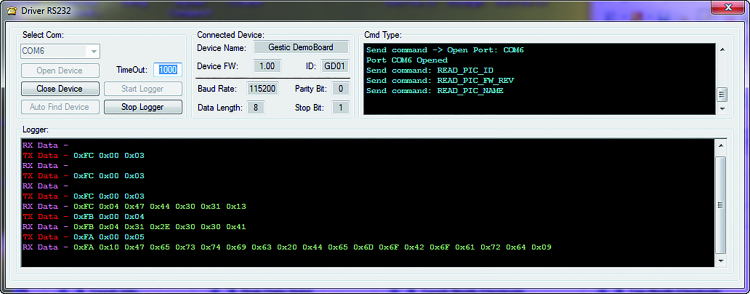
The “SetSerial” function is simply needed to initialize the serial communication, to be used with the “serial monitor”, found in the IDE to execute the monitoring of the gestures detected by the MGC3130 integrated circuit. The parameters to be delivered to the function are the communication speed that we want to use and the data configuration, that is to say the length of the data package, parity bits, stop bits, etc.
The “SetAdd” function is needed to assign the hardware address to the MGC3130 integrated circuit: in our case it is exclusively 0x42, in any case.
The “ResetDevice” function is needed to keep the MGC3130 integrated circuit in a reset condition, as long as the condition itself is not removed. The only parameter to give to the function is the pin to which the RESET line is connected. The opposite function is the “ExitResetDevice” function, that removes the RESET condition for the MGC3130 integrated circuit; as for the previous function, the only parameter to be used is the pin to which the RESET line is connected.
The “Begin” function is needed to initialize the communication lines between the Arduino board and the MGC3130 integrated circuit; the parameters it needs are just the references for the TS and RESET lines. The function initializes the I2C peripheral with the usual “WIRE.begin” function to which we have to give the hardware address of the MGC3130 integrated circuit. In order to manage the I2C communication, our library takes advantage of the standard system library, “Wire”, by including the “Wire.h” definition file within the .cpp file.
In addition to initializing the I2C interface, the RESET (Output) and TS (Input) lines are defined and configured. The RESET line is kept at a low level for a time of 250 ms, thus allowing the powering of the power-up to be stabilized. To indicate the start and the end in the initialization sequence, a series of text strings are printed on the serial monitor.
To write the text on the serial monitor the “print” or “println” instructions are used, and they are found in the “Serial” library. Every time we write a text string and use these instructions, however, we waste some of the SRAM memory, since the string is memorized right in this kind of memory.
To fix this inconvenient, we may think to save the text strings in the Flash memory, to go read them later and send them to the “print” function as a byte array, in order to avoid wasting SRAM memory. Therefore, in order to memorize the text strings in the Flash memory, the following instruction may be used:
const char MGC3130Ready[] PROGMEM =
“MGC3130 device is ready”;
To read again the string that has been memorized, we will use the “pgm_read_byte_near” function, to which we have to give the Flash memory address in which the data to be read is memorized.
We have therefore written our function that, by means of a loop, reads again all the bytes composing the string and prints it on the serial monitor.
We have to pass to the function: a pointer to the beginning of the string, its length and a boolean data type; it will tell the function if in the end it also has to print the “\n” character.
Thus, to complete the example of the string above, we will have:
ReadStringFLASH((uint8_t *)MGC3130Ready,
strlen(MGC3130Ready), TRUE);
The “GetTsLineStatus” function is needed to monitor the TS line and to detect when it is kept busy by the MGC3130 integrated circuit, in order to warn that the gesture has been recognized. As soon as the system realizes that the TS line is busy, it changes the pin state by going by itself to occupy the TS line, so to start the reading process of the data coming from the MGC3130 integrated circuit. The details concerning the management of the TS line can be found in the issue n° 195.
Once the data reading has been completed, the “ReleaseTsLine” function can be called, thus releasing the TS line.
For both the last two functions we described, the only parameter we need to give is the pin to which the TS line is connected. The “GetEvent” function is needed to read the data that has been memorized in the MGC3130’s buffer, and to save it in dedicated data structures used by the library. A following function will be then the one to decode all of the data received and to make it available for the final user and his application.
We would like to remind you that the data package used for reading the data loaded in the MGC3130’s buffer is of the kind shown in figure.

The address contained in the package is the one of the integrated circuit’s hardware: the less relevant bit indicates if we are in writing (“0”) or reading mode (“1”). The “MGC3130 message” section may be extended, as indicated in figure, so to identify two sections: “Header” and “Payload”.

By further expanding the “Header” section, as shown in figure, it is possible to notice that in the first four bytes we find the length of the data package received and, a very important thing, the package ID will be 0x91. For the list of the available ID codes we invite you to read again the article found in the issue n° 195.

Of the data read by the “GetEvent” function, during the gesture recognition, only a part will be kept into account, and in particular there will be the one regarding “GestureInfo” and the “TouchInfo”. Those will be further filtered by the bit mask, “MASK_GESTURE_RAW” and “MASK_TOUCH_RAW”, by removing the unnecessary parts. For the sake of completeness, the information concerning the x, y and z coordinates is saved.
Finally, there is the “DecodeGesture” function, that decodes the data read by the previous function and makes it available by means of a public data structure, that the user may use for his application. The gestures that are recognized and made available by the library are:
- Gesture Touch South;
- Gesture Touch West;
- Gesture Touch North;
- Gesture Touch East;
- Gesture Touch Centre;
- Gesture Tap South;
- Gesture Tap West;
- Gesture Tap North;
- Gesture Tap East;
- Gesture Tap Centre;
- Gesture Double Tap South;
- Gesture Double Tap West;
- Gesture Double Tap North;
- Gesture Double Tap East;
- Gesture Double Tap Centre;
- Flick West to East;
- Flick East to West;
- Flick South to North;
- Flick North to South;
- Edge Flick West to East;
- Edge Flick East to West;
- Edge Flick South to North;
- Edge Flick North to South;
- Clock Wise;
- Counter Clock Wise.
The library realizes the changes caught by the MGC3130 integrated circuit, and returns them on the corresponding bits of the public data structure. The gesture is recognized when the corresponding bit goes at a logical level “1”. The public data structure is allocated on 32 bits: of these, 7 are free for future developments. Moreover, it is possible to read and modify the data in the structure by operating on every single bit or, more brutally, at a byte or double word level.
If so desired (but it is not mandatory), it is possible to filter the gestures we do not want to use in our project.
In fact it is possible to configure a filter constant, which is found in the MGC3130.h file, that allows the filtering of the unwanted gestures. The constant is named “MASK_FILTER_GESTURE” and is a 32 bit value that can be configured, bit by bit. If the bit is at a logical level “1”, it means that we want to filter the gesture, vice versa we want to keep it. In our sample sketches we made use of the filter constant, in other words we left it configured at 0x00000000: this means that it is used in the “DecodeGesture” function, but that it has no effect.
To promote the study of the library, there are hidden code parts that can be activated, if needed; these sections are included between the two instructions, “#ifdef identifier” and “endif”, with identifier being a label that (when declared) activates the code section, vice versa it excludes it.
For example, the following piece of code:
#ifdef PRINT_RAW_DATA
PrintMGC3130RawData();
#endif
activates/deactivates the “PrintMGC3130 RawData” function’s code. Such a function prints the data read by the integrated circuit on the serial monitor, before they are identified by the “DecodeGesture” function. It may prove to be very useful during the study of the library and of the MGC3130 integrated circuit, since it shows the data, exactly as they come from the MGC3130’s buffer. For example, the “Flick East to West“ gesture is thus highlighted:
##############################
Row data from MGC3130
Header: 1A081191
Payload: 1F01 | 86 | 80 | 0073 | 03100000
| 00000000 | 0000 | 000000000000
##############################
To increase its readability and help to understand it, the data package is divided between “Header” and “Payload”, moreover the “Payload” is divided in sub-packages, as highlighted by the data-sheet in the GestIc library.
In addition to the hidden code section we just dealt with, there are three more: among them are the recognized and decoded gestures, and the X, Y and Z coordinates (respectively PRINT_GESTURE_DATA and PRINT_XYZ).
If you do not activate these functions, they will not take up space in the Flash memory.
MGC3130_Demo
We will describe now our first sketch, in which we will show the usage of our library, and the selected gestures’ interfacing, with respect to the relay outputs made available by the FT1079K boards.
The sketch is divided in four files, the main one being named “MGC3130_Demo”. The other files enable the management of the digital inputs made available by our electrode (“DigitalInput”), the management of the relay outputs and of the gestures returning to the outputs (“DigitalOutput”), and a last file for the management of the Atmel microcontroller’s TIMER1 (“TimersInt”), which is useful to manage all the time constants used in the sketch.

The “MGC3130_Demo” file contains the typical code sections, “void setup()” and “void loop()”, that can be found in all Arduino sketches.
In the “void setup()” section, all the needed parameters are initialized and configured, for the purpose of the sketch’s proper functioning. The same goes for the FT1079K expansion boards having hardware address 0x00 and 0x01, and for the MGC3130 integrated circuit (address: 0x42).
The input pins are initialized, by recalling the “void SetInputPin(void)” function: they are needed to manage the three buttons, P1, P2 and P3, and the J1 jumper.
The output pins, connected to the Arduino board, are then configured: in this case only the LD7 LED, and finally the TIMER1 is configured, as well as the corresponding interrupt vector, for the time constants management.
Last but not least, the state machines used in the sketch are configured.
The “void loop()” section shows the recalls to all the previously initialized state machines, as well as the code to manage the MGC3130 integrated circuit. In particular, the code we’re interested in is the following one:
if (mgc3130.GetTsLineStatus(Ts_MGC3130) == 0) {
mgc3130.GetEvent(); // Start read data from MGC3130
mgc3130.DecodeGesture(); // Decode Gesture
mgc3130.ReleaseTsLine(Ts_MGC3130); // Release TS Line
}
By using the library function:
<span style="font-weight: 400;">boolean </span><span style="font-weight: 400;">GetTsLineStatus(</span><span style="font-weight: 400;"> uint8</span><span style="font-weight: 400;">_t</span><span style="font-weight: 400;"> Ts)</span>
the TS line is tested, while waiting for it to go at a low logical level, to then keep it busy and to start the data reading process in the MGC3130’s buffer, by means of the following library function:
void GetEvent(void)
The function needed for the decoding of the read data is then recalled, in order to extract the recognized gestures, and finally the TS line is released:
void DecodeGesture(void)
void ReleaseTsLine(uint8_t Ts)
The J1 jumper, connected to the input 3 (PD3), is needed to decide if the digital outputs have to behave as monostable or bistable. If the jumper is inserted, and thus the input is at a low logical level, the outputs have to operate in a monostable mode, vice versa in a bistable mode. In the monostable mode it is possible to decide the outputs’ energizing time, by taking advantage of the three buttons, P1, P2 and P3 (the buttons are respectively connected to the inputs 4, 5 and 6, that is to say, PD4, PD5 and PD6).
By keeping the P1 button pressed for more than two seconds, the time for the monostable mode will be set at 1 second; if the P2 button is pressed for more than two seconds, the time for the monostable mode will be set at 5 seconds, etc. The possible combinations with the P1, P2 and P3 buttons, along with the corresponding selectable times (ON if the button is pressed; OFF if it is not pressed) are found in table.

The selected time is a global one and thus is associated with all the digital outputs that are driven as monostable ones. In other words, once selected, for example a 5 seconds time will be associated with all the monostable outputs. It isn’t possible to associate different times for each output.
Please notice that the bistable mode means that the output inverts its state at each associated gesture recognition; thus a detection energizes the output, a later detection will bring it to sleep mode, and so on. The monostable mode, on the other hand, energizes the output associated with the gesture and keeps it for the selected time. If the gesture associated with the output is caught before the time has expired, the same will be rearmed, thus extending the energizing of the associated output.
As hinted during the library’s description, the gestures that are recognized and made available to the user are in a total of 25; of these, only a part is returned to the relay outputs, managed by the FT1079K boards. Table shows the correspondences between the recognized gesture and the relay output, addressed to the FT1079K board.

If so desired, it is possible to return the missing gestures to the relay outputs as well, but to do so we need to add at least another FT1079K with the 0x02 address; once this has been done, the code needed to manage the new board should obviously be written.
MGC3130_Leonardo
Let’s describe now the demo created with the Leonardo Rev. 3 board. The purpose of this sketch is to command an image management software by means of the gestures recognized by the MGC3130 integrated circuit. First of all, let’s talk about the program used for the demo we are analyzing: it is the “FastStone Image Viewer” program, that can be downloaded freely.
After having installed the software on your PC, please continue with the configuration of its possible launch by means of a combination of keys; to do so you need to click with the right button on the program icon and under the “Collegamento” entry, and to set the shortcut keys. In our case we set the “CTRL+ALT+F1” combination, as shown by figure.

With this precaution we may set a gesture for the software start and as many gestures for the images’ management. The mechanism to interact with the PC software by means of gestures has to be activated; to do so we arranged two possible actions: the first consists in using the P1 and P2 buttons, found on the electrode board. The P1 button, if pressed for more than two seconds, activates the software management mechanism on the PC; if on the other hand the P2 button is pressed for more than two seconds, the mechanism is deactivated. The other method consists in using the serial monitor, in order to activate the ‘S’ ASCII character, vice versa ‘P’ is used to deactivate it.
The activation by means of the P1 button or ASCII ‘S’ character recalls the activation functions of the mouse and keyboard services, made available by the Leonardo board:
Keyboard.begin();
Mouse.begin();
Vice versa, the P2 button or the ‘P’ ASCII character recalls the deactivation functions of the abovementioned services:
Keyboard.end();
Mouse.end();
The activation/deactivation by means of ASCII characters turns out to be useful in the case in which the Arduino Leonardo Rev.3 board is connected to electrode boards that are different from the ones used for the sketchup. For example, the electrodes we showed in the previous episodes, or something else. Once this preparatory operation has been executed, the system is ready to recognize the gestures and, consequently, to interact with the images management software.
To open the program, it is enough to tap once on the central electrode: the program will be opened and the available images will be shown. To browse the images, please use the “West to East” and “East to West” gestures: the first one browses the images by going to the right, and the second one does it by going to the left. To see the images in full screen mode, it is enough to Tap once on the “West” electrode, and to exit the full screen view it is enough to Tap once on the “East” electrode.
To enlarge a picture (Zoom +) please perform an “Edge West to East ” gesture, and to reduce the picture (Zoom -) please perform an “Edge East to West ” gesture. When we are looking at a zoomed in picture in full screen mode, it is possible to move the enlarged picture via the gestures, ”West to East”, “East to Ovest”, “North to South” and “South to North”.
Finally, it is possible to rotate the selected pictures: to do so please perform a circular clockwise movement, in order to rotate the picture to the right, and a counterclockwise movement to rotate the picture to the left. To close the software, you just need to double Tap on the central electrode.
From Openstore
Gesture Raspberry Pi e Arduino – kit

[…] Gestic Meets Arduino: gesture recognition with ArduinoPosted 5 days ago […]
Great stuff!
[…] Gestic Meets Arduino: gesture recognition with Arduino […]
Can somebody provide the complete arduino code for all gestures @musiclolo2@gmail.com
Thanks in advance