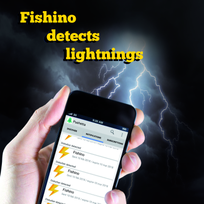
A new library for Fishino boards allows to easily send multi-device push notifications using Pushetta.
Let’s try it out with our lightning detector.
Since the name launch of the first board from the Fishino series, we have developed and proposed new versions and enhanced the software support, with the addition of firmware features and new libraries making the “little fish” board more and more competitive and complete. In these pages, we want to describe a new library called Fishetta. The name comes from the fusion of Fishino and Pushetta, a web app notifications allowing to send push educations to multiple devices using one simple API KEY. Without going in depth (for the complete description of Pushetta and its functions, we refer you to the dedicated article published on issue # 194) we just remind you that in order to send out a push notification from a device such as an Arduino (or Fishino in our case) you have to send out an HTTP GET request to the address api.pushetta.com, including the channel name, the API key and the text of the message.
With that said, let’s move on to describe our new library, which can you freely download from the website , or from the GitHub repository .
In order to better understand Fishetta, let’s recall some of the base concepts of Pushetta: it is an all Italian web app that allows to send out to push notifications to more devices simultaneously: smartphone, tablets, smart TVs etc. There are several advantages compared to traditional communication media (emails, text messages): traceability, immediacy and free of charge operation. You don’t have to insert any phone number and, when we access the dashboard, we can see stats like the number of users subscribed to the channel and the number of notifications sent. We can also adjust the channel settings, for instance, we can hide it so that other users won’t be able to subscribe to the channel, or we can make it publicly available.
How it works
In order to use Fishetta in our application, we must add the line #include<Fishetta.h> in the corresponding sketch and declare two constants: channel name Pushetta and API key, which is unique for each user. Then, we will declare the library object so that we can also associate the two constants. The declared object is structured as follows:
Fishetta push (CHANNEL,APIKEY);
All we have to do in order to send the push notification is recall the function
push.sendPushNotification(String);
We must point out that this function is a boolean one, so we are going to receive a “true” value when sending is successful or a “false” value otherwise.
But what does our Fishino do when it sends out a notification? Well, in List 1 we can see the code (from the file Fishetta.cpp) needed to make the HTTP GET request.
Fishetta is very useful because it doesn’t require many resources and doesn’t need to establish an HTTPS connection with the server, therefore reducing the RAM usage of the WiFi ESP2866 module installed on Fishino boards to the bare minimum.
Listing 1
bool Fishetta::sendPushNotification(String text)
{
if (client.connect(_serverName, 80))
{
//Send data to the server
client.print(“POST /api/pushes/”);
client.print(channel);
client.println(“/ HTTP/1.1”);
client.print(“Host: “);
client.println(_serverName);
client.print(“Authorization: Token “);
client.println(apikey);
client.println(“Content-Type: application/json”);
client.print(“Content-Length: “);
client.println(text.length() + 46);
client.println();
client.print(“{ \”body\” : \””);
client.print(text.c_str());
client.println(“\”, \”message_type\” : \”text/plain\” }”);
client.println();
client.stop();
}
return true;
}
Our application
In issue # 217 of our magazine, we have talked about the AS3935 sensor, useful to detect lightning up to 40 km away. In this article, we’re going to associate a detection event to the sending of a push notification. First, we must point out that we need to write another library to use the sensor in I²C-Bus. In fact, those available on the web turned out to be incomplete. The Fishino AS3935 library can be downloaded from the Fishino website and allows to use of the sensor with the SPI or the l’I²C.
so, let’s take a look together at the hardware and sketch that allows the hardware to function.
Creating the channel
In order to create a channel, we must go on Pushetta and sign up, choose a username and the password and insert your email address (Fig. 1). After registration, we can access the reserved area and browse to the “Channels section”, therefore we click on “Add a channel”.

Fig. 1
We will see a screen as shown in Fig. 2; now, all we have to do is fill in all the fields, insert an image to identify each channel and click on “Create”. Now we browse to the “Dashboard” section and write down the API key that we will need later on.

Fig. 2
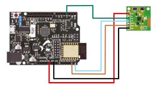
Hardware needed
In order to create our application, we must connect the lightning sensor breakout board described in issue # 217, following the wiring diagram shown at the top of this page. From it, we can see that the Vcc pin of the sensor is connected to the 5V of our Fishino Uno (theoretically, we can also power it using 3,3V). Pins GND, SDA and SCL of the sensor are connected to their counterparts on the board. The IRQ of the AS3935-based breakout is connected to pin D3 of Fishino; this will generate the interrupt signal each time lightning or a consistent radio-electric disturbance is detected. Everything you need to wire the two units is recapped in Table 1.
Table1

The Arduino sketch
Now, let’s move on to analyze the code for this application, reported in List 2; as you can see, we are going to define some constants and create the objects for our libraries: AS3935_ADDRESS identifies the I²C-Bus address of the AS3935 module, which is normally 0x03; IRQ_PIN is the pin to be connected to pin D3 on the board. We will not be using the pin D5 defined as SI_PIN, because it has to be connected only when you want to use the sensor as SPI. By defining the object AS3935 we notice “digitalPinToInterrupt(IRQ_PIN)”: this way we can set pin D3 as an interrupt pin. In fact, if we omitted this part, our Fishino/Arduino wouldn’t be able to recognize their interrupt. The code reported in List 3 is included in the sketch setup and is used to establish a connection with the sensor, resetting the registers, calibrate it and select the working mode. Whenever the sensor is installed in a closed environment, we do not have to edit the code. If, on the other hand, we wanted to use it outside, we would have to edit AS3935.setIndoors(); in AS3935.setOutdoors(); this way, the sensor will automatically regulate the gain. Now, let’s move on to analyze the code found in the loop of our sketch, which you can see in List 4. Each time a loop is started, the Fishino board checks for a status change on the interrupt pin, and then brings the value to zero. It will then read the value on the sensor’s registry to determine the cause of the change. Based on the value from the registry, we can determine if a lightning bolt or a disturbance was detected or if the noise level is too high. In case of lightning detection, all we have to do is establish the distance: if the value is 1, we will receive a notification with a warning because the lightning bolt is on our heads. If the value ranges between 1 and 63, we will receive a notification indicating lightning bolt distance. If the value is higher than 63, the lightning bolt is out of range, but we will receive a notification nonetheless.
Listing 2
#define AS3935_ADDRESS 0x03
#define IRQ_PIN 3
FishinoAS3935 AS3935(AS3935_ADDRESS, CS_PIN, digitalPinToInterrupt(IRQ_PIN));
Fishetta push(CHANNEL,APIKEY);
Listing 3
Wire.begin();
Wire.setClock(400000);
Serial.println(“Starting”);
AS3935.reset();
if (!AS3935.calibrate())
Serial.println(“Tuning out of range, check your wiring,
your sensor and make sure physics laws have not changed!”);
AS3935.setIndoors();
AS3935.setNoiseFloor(6);
AS3935.enableDisturbers();
printAS3935Registers();
AS3935IrqTriggered = 0;
attachInterrupt(digitalPinToInterrupt(3), AS3935_ISR, RISING);
Listing 4
if (AS3935IrqTriggered)
{
// reset the flag
AS3935IrqTriggered = 0;
// first step is to find out what caused interrupt
// as soon as we read interrupt cause register, irq pin goes lwo
int irqSource = AS3935.getInterruptSource();
// returned value is bitmap field, bit 0 - noise level too high ,bit 2 - disturber detected, and finally bit 3 - lightning!
if (irqSource & 0b0001){
Serial.println(“Noise level too high, try adjusting noise floor”);
push.sendPushNotification(“Noise level too high, try adjusting noise floor”);}
if (irqSource & 0b0100){
Serial.println(“Disturber detected”);
// push.sendPushNotification(“Disturber detected”);
}
if (irqSource & 0b1000)
{
// need to find how far that lightning stroke, function returnsa pproximate distance in kilometers,
// where value 1 represents storm in detector’s near victinity, and 63 - very distant, out of range stroke
// everything in between is just distance in kilometers
int strokeDistance = AS3935.getLightningDistanceKm();
if (strokeDistance == 1){
Serial.println(“Storm overhead, watch out!”);
push.sendPushNotification(“Storm overhead, watch out!”);}
if (strokeDistance == 63){
Serial.println(“Out of range lightning detected.”);
push.sendPushNotification(“Out of range lightning detected.”);}
if (strokeDistance < 63 && strokeDistance > 1)
{
String stroke = “Lightning detected “;
stroke += (strokeDistance, DEC);
stroke += “ kilometers away.”;
Serial.println(stroke);
push.sendPushNotification(stroke);}
}
}
App configuration
Now, we can set up the app: we take our smartphone and, after downloading the “Pushetta” app from Play Store or iTunes, we configure it in order to receive push notifications. At first launch, we will see the screen shown in Fig. 3;

Fig. 3
after browsing to the “Subscriptions” section, we are going to click on the top right button on the screen and then on “Add custom channel” (Fig. 4).

Fig. 4
Now we can insert the name of our channel and press enter. If everything goes well, we will see a pop-up just like the one shown in Fig. 5.

Fig. 5
Now, our device is ready to receive notifications from the channel to which we have subscribed. Fig. 6 shows a map screen reporting the lightning’s readings.

Fig. 6
Conclusions
This is our presentation for the new library for Fishino boards; all you have to do now is an experiment to make your life easier and more and more connected to the web.
From Openstore
