
The Fishino version of the powerful and popular board, Arduino MEGA: a revised hardware with a different power section.
Not so much time has passed, since we presented our Fishino UNO, a board that is compatible with Arduino UNO and that is provided with interesting additional peripherals on board, among which a WiFi module, a microSD card reader and a RTC (Real Time Clock).
As anticipated back then, the board wasn’t meant to be a “unique piece”, but the first one of a complete series of Arduino-compatible boards, having better performances and extended functions that we were missing. In this article we will then present the second board in the series: Fishino MEGA. It is a board that is compatible with Arduino Mega. In its hardware we implemented a significant innovation: the possibility to have it battery powered.
As a first thing, let’s see Fishino MEGA’s complete features:
- it is 100% compatible with Arduino MEGA;
- it has a WiFi module on board, and is fully provided of libraries we developed;
- it has a microSD reader on board;
- it has a RTC module on board;
- it has an integral switching power source, capable of supplying about 800 mA-1A (for a total between 3 and 5 volts), starting from an input voltage that may vary between 3 and 20 volts;
- it has a single cell LiPo battery connector and a battery charger on board;
- it has an additional side connector, in order to solve the well known misalignment bug found in the Arduino series, that makes it impossible to use it along with stripboards and breadboards.
Circuit diagram
The “highlight” of this new board is the power source section, that required a long development time and that also brought to the creation of a distinct multi-usage power supply. For a detailed description of the SEPIC converter that has been used, please refer to the said article, while here we will limit ourselves to making a brief description and to analyzing the surrounding circuitry in detail.
Let’s start from the power supply inputs, that bring three voltages:
- VLiPo, that refers to the lythium polymer (LiPo) rechargeable battery’s connector;
- VUSB, that refers to the microUSB connector;
- VIN, that refers to the PWRIN power supply’s plug.

The two voltages that are usually higher, that is to say VUSB and VIN (in truth we may apply a lesser voltage to the PWRIN connector, and up to 3.2 volts, even though it is inadvisable since it implicates a loss in efficiency), pass through the two Schottky power diodes, D6 and D7, while the “lower” voltage, for efficiency reasons, is directed towards the MOSFET having a P channel signed as Q2.
Let’s omit the Q2 functioning for a second (we will shortly return on the subject), and consider only the diode that is internal to it; the three diodes (D6, D7 and the diode that is internal to the MOSFET) create an OR power port, that enables to obtain the greatest voltage among the ones found at the inputs; let us suppose, for example, to have only the VLiPo voltage, of about 3.7V: in this case the diode that is internal to the MOSFET will turn out to be directly polarized, by bringing the same voltage towards the converter, and that it cannot return towards the other two inputs, because of the presence of the D6 and D7 diodes that are inversely polarized.
Now, if we connect the microUSB connector, the VUSB voltage (5 volts) will directly polarize the D6 diode and reach the converter, while the diode that is internal to the MOSFET is found with a voltage of 4 volts at the anode and a 5 volts one at the cathode: therefore it turns out to be inversely polarized, interdicting itself.
If, finally, we also power the PWRIN input with a voltage that is greater than 5 volts – for example 15 volts – the D7 diode will turn out to be directly polarized, thus bringing the VIN voltage to the converter, while the D6 diodes and the one that is internal to the MOSFET will be inversely polarized, thus interdicting themselves.
We therefore reached the intended purpose, that is to say a totally automatic commutation of the power source.
Let’s return now to the MOSFET that is inserted on the LiPo connector’s positive line; apparently it is an unnecessary component, since its internal diode is enough to achieve the commutation; unfortunately the diodes (even the Schottky ones) have a voltage fall at their ends that – no matter how small – causes voltage losses that turn out to be significant with high currents.
We will give a practical example: let’s assume that the load (after the converter, we will talk about it later) absorbs 800 mA at a voltage of 5 volts, and that the converter has an excellent efficiency (about 90%), which is close to the actual one in our circuit. We will also suppose that the Schottky diodes present a voltage fall of about 0.5 volts. By powering everything by means of the PWRIN plug with a voltage of 15 volts, we will obtain a current absorption of:

It is immediately possible to notice the great advantage of using a switching power supply: the absorbed current decreases with the input voltage increasing, differently to what occurs with the linear regulators that are used by the Arduino series, in which the absorbed current remains identical to the supplied one and, being multiplied for the input/output voltage fall, it causes a significant thermal dissipation on the part of the regulator.
In the formula, the diode’s voltage fall has been considered, (0.5 volts), which brings the total efficiency to:
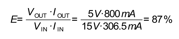
against a theoretical 90%, given by the converter. Therefore, the diode causes an efficiency loss of 3%, that we may consider as negligible. It is possible to notice from the formula that the impact of the voltage fall on the diode increases as the input voltage decreases, which is logical since the switching transfers the power, converting its voltage and current: as the voltage increases the current decreases and vice versa.
Let us make the same calculation, now, by using an input voltage of 3.6 volts (a value that is close to the one of the LiPo battery):

As a first thing we may see that, in order to obtain 800 mA as an output, we have to draw no less than 1.433,7 mA from the input; the actual efficiency tehrefore becomes:

In this case, the voltage drop on the diode brought to an efficiency loss of a whopping 12.5%, and right when a greater efficiency would be needed, given that we power the board by means of batteries.
Moreover, a 0.5 volts fall on the diode, with a 1.4 amperes current, would correspond to a dissipated power of 0.7 W, that on a small size component would bring a considerable temperature increase.
The MOSFET, on the other hand, does not have a fixed fall at its ends, but it presents – when conducting – a resistance that depends on the component used; in our case it is worth 100 milliohm, at best.
The calculation gets a bit more complicated here:

which is a second grade expression in ILiPo; by inserting the values and by solving it, you will obtain:

A current that is well below the 1.433,7 mA in our previous case. With such conditions the efficiency becomes:

Therefore the MOSFET causes a loss of the 3.2% only, against the 12% of the diode.
Since the MOSFET’s usefulness has been established, all we can do is to find a way to bring it to conductance, when needed. Since it is a P channel, in order to do so we need to polarize its gate by means of voltage that is a negative one with respect to the source: given that it is a low gate voltage MOSFET, in order obtain the required resistance (RdsON under 100 mΩ), 2.5 volts are enough. The R12 resistor, that negatively polarizes the gate, takes care of it. In contrast, the D4 and D5 Schottky diodes for small signals, along with the R11 resistor (the latter is used in order to avoid that a voltage greater than the tolerable one arrives on the gate, thus it operates as a voltage divider, along with R12), deal with bringing the MOSFET to the interdiction, when a voltage is found at the USB and/or PWRIN inputs.
The chosen voltage reaches U3’s pins 4 and 5 (U3 is the foundation of the SEPIC converter). The converter has been widely described in the dedicated articles, therefore we will only give a brief sketch about it here; the advantage of this diagram lies mainly in the possibility to obtain an output voltage that is greater than the input one, thus adding the advantages of a Buck converter to those of a Boost one, but still using a single switching integrated circuit only.
The voltage output is regulated by the voltage divider (here composed of R13 and R14), that supply a reference voltage of 0.6 volts at the integrated circuit’s FB input, when 5 volts are found at the output.
At the SEPIC converter’s output we therefore find a 5 volts direct current. The green POWER LED operates as a power light, and it may be deactivated by cutting the SMD PWLED bridge, thus reducing the consumption to a minimum (if you want to power Fishino MEGA by means of a battery, which was requested by many Fishino UNO’s users).
The 5 volts voltage exiting the SEPIC enters a further switching converter: this time it is a simple Buck (or step-down) converter that, for efficiency reasons, has been created by means of a synchronous converter, that is to say that it has been supplied with a second internal MOSFET, in the place of the Schottky diode that is commonly used. 3.3 volts exit this converter, and they are needed in order to power the WiFi module and the microSD reader: as anticipated, the available current is about 800 mA – 1 ampere as a total between 5 volts and 3 volts, which enables to power many external modules without the power supply suffering a crisis, as it often happens with Arduino and its linear regulators.
By the way, you will be able to notice the extremely reduced size of the three inductors and of the power supply’s filter capacitors: this has been possible thanks to the high operating frequency of the switching integrated circuits (above one MHz) and to the availability of high capacity ceramic capacitors.

Battery charger’s stage
The U2 integrated circuit (the well known MCP73831) is the heart of this stage: inside it contains all the circuits needed for the charging and keeping charged a single cell lithium polymer battery. The integrated circuit is powered by means of a 5 volts voltage, applied to the VIN pin, while the battery to be charged is connected to the VBAT pin, and uncoupled via a 4,7 µF ceramic capacitor, that assures the integrated circuit’s stability. The chip integrates a system used in order to detect the battery’s presence, to say it all it is a quite problematic system that sometimes may detect it even when it is not connected, and particularly at the low voltages, when powering Fishino MEGA, even though this does not invalidate its functioning: the only setback regards the LEDs lighting, in those cases. The PROG pin is used in order to set the charging current, that in our circuit may be chosen between two values: about 100 mA with the bridge signed as 500 MA that is kept open (only the 10 kohm R9 resistor is inserted) or about 500 mA with the bridge closed, which corresponds to inserting the 2.7 kohm R10 resistor in parallel to the R9. The formula used in order to set the charging current – in the case you believed there is need to change it – is the following one:

here, RPROG is the resistance applied to the PROG pin, expressed in KOhms, and IREG is the charging current, expressed in mAs. The same PROG pin, if connected to the positive of the power supply and left fluctuating (disconnected) is used in order to disable the charging, thus deactivating the integrated circuit’s internal circuits and reducing their consumption (almost to zero); this is used in our diagram, by inserting the Q1 MOSFET, a common 2N7002 having a N channel that, when the gate is negatively polarized, actually disconnects the two programming resistors, therefore making the PROG input a fluctuating one.
The MOSFET is driven by the same signal used in order to drive the Q2 battery’s switch, even if in an inverse mode: a voltage at the VUSB or VIN inputs brings it to conductance and activates the charging, while when it is missing (when the circuit is powered by the battery alone) the MOSFET is interdicted and the charging is deactivated. In the end of this description, please notice the jumper signed as MEAS (measure) that enables the connection of the controller’s ADC0 analog input to the battery, in order to execute a check of the charging state.
USB interface
The USB interface is the same that has been used for Fishino UNO, therefore here we will limit ourselves to a brief outline, and will refer to the said article for an in-depth description. The stage revolves around the now well-known CH340G, an extremely good alternative to the much more popular FT232 or to other solutions having microcontrollers: the chip has been chosen for both economic reasons and for the simplicity of the circuitry, the performances being equal. The integrated circuit provides – as an output – all the signals of a RS232 standard interface, of them we use only those for the data transmission/reception (Rx and Tx) and the DTR signal used for the automatic reset in the programming phase, as in the original Arduino, which enables the loading of the sketches without having to press buttons or to activate switches.
Later we will return on the subject of the Reset circuitry, since with respect to the original it has been modified, so to enable a future reprogramming of the ATmega via WiFi.
ATmega 2560
In this section the Fishino MEGA’s diagram does not distance itself from the one for Arduino MEGA; the controller is the same, and is provided with the usual 16 MHz crystal, with 2 capacitors on the oscillating circuit and with a certain amount of uncoupling capacitors on the power supply lines, that are needed in order to avoid that disturbances on the power supply lines might influence the chip’s functioning. A note on the I/O connectors: as you may see from the images, a small 10-pins connector has been added, and put beside the standard one, but slightly staggered so to use a standard stripboard for the shields, therefore solving the long-standing problem of the wrong step of the Arduino connector, and without invalidating the compatibility with the existing shields.
SPI interface
Level converters
Even this section turns out to be practically identical to the one seen in Fishino UNO; it is used in order to adjust the ATMEGA’s 5V logic levels to the 3.3V ones of the WiFi module and of the microSD card. The conversion is simply carried out by means of resistive voltage dividers (resistors from R22 to R31) in the 5V -> 3.3V direction, while in the opposite direction we take advantage of the fact that the 5V logics accept high values (well below 3V) as signals, thus proving to be compatible with the 3.3V logics. The MISO (Master In Slave Out) signal should not require an adjustment, in theory, given that the direction goes from the 3.3V logic to the 5V one; we inserted it anyway, in anticipation of the future firmware’s extension of the WiFi module, that will enable the loading of the sketches by means of the same, which requires a roles exchange, therefore in that case the WiFi module becomes the master and the ATmega becomes the slave.
MicroSD card interface
The interface is the same we described for Fishino UNO, and reflects the SD shield (or similar combinations); it operates by means of the SPI lines, among which the MOSI (data from the ATmega to the SD, Master Out Slave In), the MISO (data from the SD to the ATmega, Master In Slave Out) and the SCK (clock). The values going towards the SD card are obviously reduced by the level converters of the previous paragraph.
The card selection is carried out by means of the SDCS line, that is active at a low level. In this case the level conversion is carried out by means of a resistor (R23) towards the positive and a diode (D9), that enables the passage of the negative currents only.
The diagram that has been chosen allows to have a standby card, when the SDCS signal (that is connected to Fishino MEGA’s digital pin 4) is not used; with the pin in the three state mode (that is to say, at high impedance) the diode does not conduct and on the SDCS input there is a high value that deactivates the board. The interface is a totally compatible one with the Arduino shields, therefore it uses the same libraries that are used for its functioning, as it will be possible to see in the examples later shown.

WiFi section
Even the WiFi module has remained unchanged with respect to the one in the Fishino UNO board.
Therefore we will only report some important notes, that is to say the kind of communication with the ATmega, that is carried out via SPI interface and thanks to a firmware we purposely developed and to some circuital gimmicks, such as the D10 diode that is used in order to force the module’s GPIO15 pin to the reset at a low level; without it the module itself would be booted in the “Loading from SD” mode, thus making it unusable. This turns out to be needed, since the GPIO15 line also has a module’s Slave Select (SS) function and therefore it cannot be directly connected to ground.
All the module’s useful pins are brought on a connector (ESPCONN), as reported here as follows.
- GPIO0: in addition to being usable as a digital input/output, it is needed in order to select the starting mode, when booting the module. The latter may in fact be started from an internal Flash memory (normal functioning, GPIO0 set to 1) or from a serial interface, which is used for the firmware’s reprogramming (GPIO0 set to 0).
- GPIO2, GPIO4 and GPIO5 are available for the usage as digital pins, and it is possible to take advantage of them by means of the dedicated library functions, as if they were extensions of Arduino’s digital pins.
Rx and Tx compose the module’s hardware serial port and are also used in the firmware’s programming phase. A future firmware extension, that will enable its use as an additional serial port that will allow Fishino MEGA to have a further serial port.
- CH_PD is the module enabling pin. By bringing it to high level, the module turns out to be enabled (default settings), while a low level puts the ESP in standby mode, thus reducing its consumption to almost zero.
- RESET is ESP’s hardware reset, which is active at a low level.
- ADC is ESP’s analog input, that is directed towards a 10 bit A/D (1,024 possible values).
RESET Circuitry
Fishino MEGA’s reset section is the same of the one found in Fishino UNO, that you already know; as previously hinted, it turns out to be more complicated than the one in Arduino MEGA, for the following reasons:
- it is needed to reset both the ATmega and the ESP, at the pressure of the reset button, at the start and at the programming request on the part of the IDE.
- in order to execute ATmega’s programming via WiFi, the ESP module must be able to reset the same ATmega, without having in turn to self reset itself.
Let us start from the DTR signal, that comes out of the USB/Serial (U1/CH340G) interface; as anticipated, this is put at a low level when the serial port is opened. By means of a C5 capacitor (ceramic 1 µF, as opposed to the 100 nF of the original one, used so to extend the reset pulse) a short pulse is generated and, once it is passed through the SMD RESEN jumper (when cutting it, it is possible to deactivate the autoreset), it reaches the “external reset” line, to which the reset button and the pin 5 on the programming connector (ICSP) are connected.
Differently from the original circuit, in the Fishino boards a diode (D2) is inserted between the RESET line and the ATmega’s pin. The purpose of this diode (and of the D3 diode we will see later) is the one to reset the ATmega only, withouth having however to convey the signal to the ESP as well.
In brief:
- by pressing the RESET button, or by connecting the serial, the reset pulse reaches both the ATmega (via D2) and the ESP (directly), thus resetting them both;
- a signal on the ATRES-ESP line, that is generated by the ESP (in the case the reprogramming via WiFi has been enabled), reaches the ATmega’s reset line through D3 but, because of D2, it cannot propagate itself in the same ESP.
By means of this system we therefore gave the possibility to the WiFi module to control the ATmega’s reset line that, along with the SPI interface, enables its reprogramming without even the need of a preloaded bootloader. In practice, once the firmware’s development has been completed, it will be possible not only to reprogram the ATmega via WiFi, but to make it by using the space usually reserved to the bootloader as well.
RTC module
Let us conclude the discussion about the circuit diagram with the RTC (Real Time Clock) module, composed of a classic Maxim’s DS1307, of a 32 kHz crystal, of a backup battery and of a pair of resistors on the
I²C line. The diagram is as classic as it gets, and is completely compatible with the existing Arduino libraries; all the functions are managed by means of the I²C line (SDA/SCL).
USB driver
Fishino MEGA uses an USB/Serial converter of the CH340G kind, which needs of specific drivers, at least for Windows (until version 7 included, it appears that starting from version 8 onwards the drivers are already found there) and for Mac systems. As for the Linux environment, on the other hand, the drivers are not needed since they are already found in the kernel. The drivers for Windows and Mac may be downloaded from the fishino_website’s download section.
WiFi module’s firmware update
Fishino MEGA is supplied with the firmware version available at the moment of the assembly. Since it is being continuously developed, it is surely convenient to execute an immediate update and it is advisable to repeat it periodically. The available Arduino’s libraries are in fact continuously updated, on the basis of the new possibilities given by the firmware.
The update procedure is simplified by a specific program, that is available for both Windows and Linux; it executes the operation in a completely automatic and error-free way. For the next future a Mac version of the flasher is to be expected.
The steps needed for the update are as follows.
1) Please load a sketch that does NOT use the serial port; BLINK, the basic example (the one making the LED flash on the board) is perfect for the purpose. This passage is needed in order to avoid disturbances between the loaded sketch and the serial connection between the ATmega and the ESP. If the flashing program does not detect Fishino, it is 99% likely that it depends on a wrong sketch being loaded.
2) Please connect Fishino’s TX port to the ESP-TX port on the ESPCONN connector, and Fishino’s RX port to the ESP-RX port on the ESPCONN connector.
- Please connect the GPIO0 port to ground, by means of a small cable or a bridge, and still to the ESPCONN connector.
- Please connect Fishino to the PC (or press the RESET button, if it is already connected).
- Please launch the FishinoFlasher program, and make sure that the PC is connected to the Internet.

If the connections have been correctly carried out, the program will detect the port to which Fishino has been connected, and will determine the model and the firmware version currently installed; it will connect to a remote server and will download the list of the available firmwares; the latest one will be shown and it will be anyway possible to select the previous versions, in the case you wanted to carry out a downgrade. By clicking on the “Flash” button, the update procedure will be started, at the end of it a confirmation message will appear. In order to exit the program, you need to click the “Exit” button. In the case Fishino is not automatically detected, it is possible to try to manually select the port. It is however possible that some mistakes have been made with the connections. The manual selection turns out to be indispensable in the rare case that two or more Fishinos are connected to the PC at the same time, in that case the first one is automatically detected, but it is still possible to select another one. Once the procedure has been completed, it is sufficient to remove the three connections and Fishino will be ready fo the usage with the new firmware.

CONCLUSIONS
The presentation of the second board of the Fishino series ends here, we forewarn about the forthcoming issue concerning the next board, that will be Fishino Guppy: this board, that is compatible with Arduino Nano, is distinguished from it because it is supplied with WiFi, microSD and switching power source with a battery, all features that are typical of our technological “little fish”.
Available libraries
Currently two libraries for Fishino’s management have been created, they are described as follows.
- Fishino library: it exactly corresponds to Arduino’s Ethernet or WiFi library. In this library the FishinoClass classes (low level management, analogous to Arduino’s EthernetClass or WiFiClass) are defined, and the respective FishinoClient classes (analogous to EthernetClient and WiFiClient), FishinoSecureClient (not found in the original libraries, it enables connections to the SSL/HTTPS secure servers) and FishinoServer (EthernetServer and WiFiServer). These classes are used in a way that is almost identical to the original ones, therefore in the existing sketches that use Ethernet or WiFi, it is sufficient to change the type of the various variables in order to achieve their functioning with Fishino’s WiFi. The only (slight) differences concern the initialization, given that Fishino’s WiFi module is provided with additional features, with respect to the original WiFi.
- FishinoWebServer library: this is the porting of the well-known TinyWebServer on Fishino; it enables the creation of a complete web server on the board. Moreover, in the download package a Flash library has been added, since it is used by FishinoWebServer in order to move the constants in the Flash memory, thus freeing the little RAM memory available. However, this library may still be found on the Internet, but we attached it for ease of use. The remaining libraries that are needed are already available in the various downloads for Arduino’s IDE; in particular, the SD (for the management of the microSD cards) and the RTClib (for the management of the RTC module with the DS1307) are needed, along with other system libraries. The libraries are continuously developed and soon they will be supplied with additional functions; the management of the additional digital I/Os found on the ESPCONN connector has already been recently implemented, while the management of the serial, of the analog input and of the PWM outputs (still on the ESPCONN connector) is to be expected shortly.
In the download package other libraries are found, they are mostly used for the demos that have been developed and/or that will be developed in the future; we advise to install the whole content in the dedicated Arduino folder.
From openstore
