In this second and final post we will go deep inside the Ethernet audio streaming transceiver firmware.
Recently, we have presented an Ethernet audio streaming unit. In particular, we have shown how to configure the boards to work with other similar devices or with VLC Media Player, setting up a point-to-point or a broadcast streaming in all possible configurations. Also in the first episode, we analyzed the electrical circuit and the components choice. Now it is time to describe the board software advanced options and how to update firmware via Internet or manually.
AUTHENTICATION AND LOCAL NETWORK
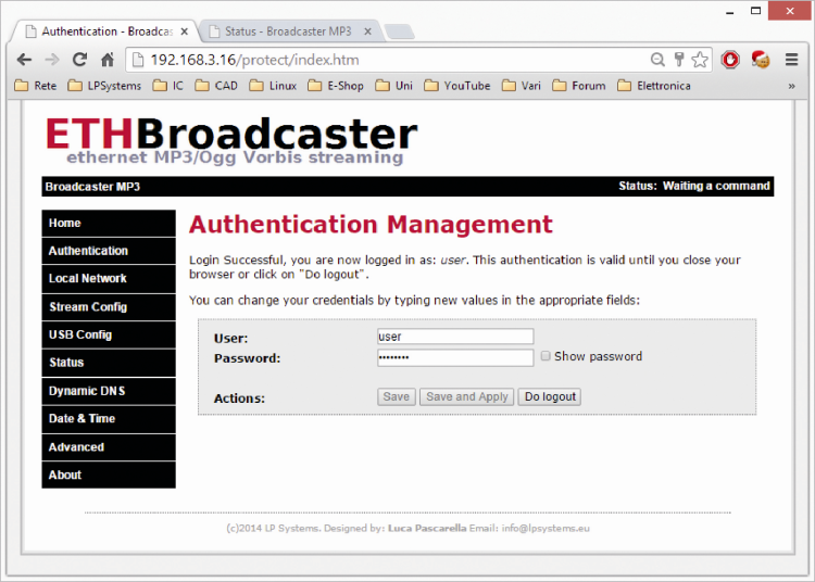
In the Authentication page, you can change your credentials to access all the restricted areas. The software allows two roles, each accessible with username and password. The software recognizes as Admin the role with the highest level of administrator privileges, only it can change all available settings; instead the role with less rights is simply “User”. When you login as administrator in the Authentication page, you get a form (first figure), where you can change your credentials; similarly, when you login as user (as in second figure) you can change the user role settings only.
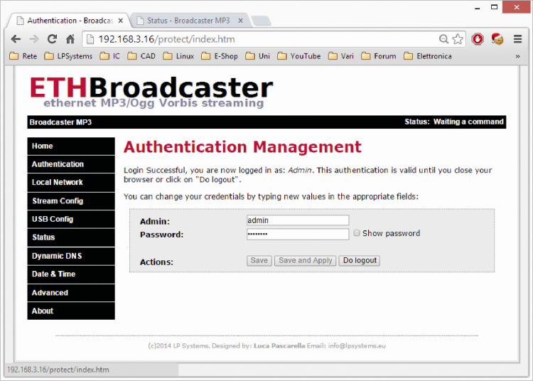
Each time a user changes values on an editable field, the “Save” and “Save and Apply” buttons are activated, allowing the saving of changed information. The difference between the two commands is that while the first (Save) saves the changes without ending the current session (so you can modify other parameters), the second button (Save and Apply) saves data and close the session, asking your login data again if you want continue making additional changes.
The last Authentication page command is “Do logout”, which terminates a previously authenticated session; the same effect is obtained by closing the browser.
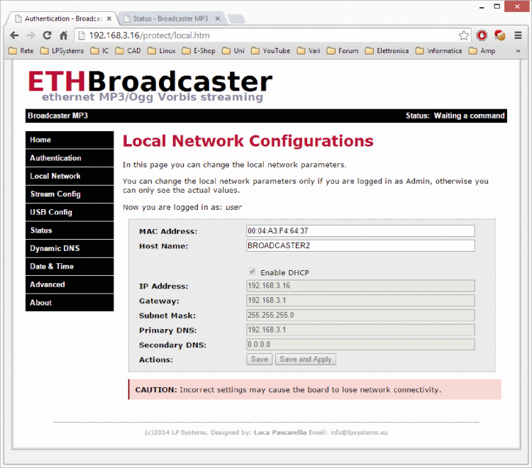
From the Local Network page, however, you can configure the network settings: in particular, you can view or change the MAC address and the network basic input / output system of the network device. The latter, known as NetBIOS is a session layer protocol developed by IBM and Sytec, whose ease of use has made it a widely used standard especially in MS Windows environment. It is not a protocol of fundamental importance, but in local networks where IP addresses are often dynamically assigned by the DHCP server, it helps identifying the device: it is enough to perform searches by name rather than by IP (dynamic).
The network devices identification process is very similar to the name service implemented by the DNS and the idea behind is the same, i.e. providing some mechanism to contact a network device from its associated unique name. On Windows, the service is often enabled by default, while on Unix systems it is necessary to enable it manually.
We conclude the description of available commands in the Local Network page with “Enable DHCP“ checkbox, that enables the Dynamic Host Configuration Protocol (DHCP): when the checkbox is unchecked, the page allows manual editing of IP Address, Gateway, Subnet Mask and DNS servers.
When you opt to use DHCP (the checkbox is checked), network parameters are not editable and the fields are used to display the current configuration obtained by DHCP.
USB CONFIG
The USB Config page lets you interact with the USB pen-drive: in particular, you can explore the mass storage device connected to the transmitter and then checking its stored files; a representation is visible in figure.
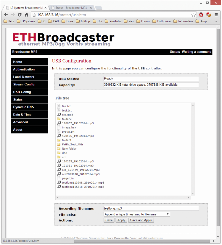
You can also change the default file name given to recordings done from the network stream, with the Recording filename setting. The same form lets you choose actions to be taken if the filename already exists. The possible actions are two and are “overwrite the existing file” or “add a unique time stamp”.
The time stamp will be formatted in the following way: hhmmss_GGMMYYYY where hh stands for hour, mm stands for minutes, ss stands for seconds, DD for day, MM for month and YYYY per year.
The actions associated to “Save”, “Apply” and “Save and Apply” buttons are respectively save to permanent memory and activate only at the next reboot, apply changes immediately and do not save them in memory and, ultimately, save and apply changes immediately.

DYNAMIC DNS
Dynamic DNS (DDNS abbreviated) is a technology derived from the Domain Name System (DNS), which allows you to associate an IP address to network or domain names. The main difference between the two services is that while the DNS is administered worldwide through a distributed database and the insertion of a new DB record is regulated by a hierarchical authorization mechanisms that makes it “static”, the DDNS implements more or less the same functionality but for devices that are subject to frequent IP change (like domestic ADSL without a public IP).
This feature allows you to bypass the problem of having a dynamic IP using just one of the many DDNS services available on Internet (some of them free).
To ensure that there is always the right matching, the device running the DDNS client must contact the remote server and update the database entry with the new IP address value assigned each time.
In order to make the board always remotely available, even if the Internet service provider is constantly changing the assigned IP address, you can click on the Dynamic DNS menu item and enter the requested parameters for one of the three DDNS services available provides an example in which the broadcaster.noip.me host name is associated to the board under test.
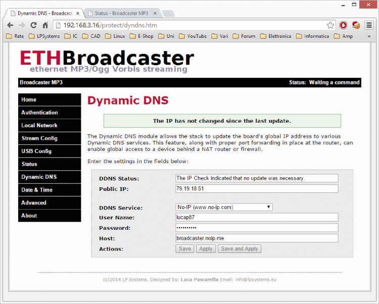
In the “public IP” field, as shown also in the figure, there is the public IP used to access the Internet. If the board is connected to a home LAN, you should configure router’s port forwarding, i.e. you must tell the DNAT service that when external LAN requests match a particular pre-assigned port number, those incoming connections must be correctly routed to our board and not dropped!
DATE & TIME
The board implements a hardware clock and a calendar: clicking on Date & Time menu item you can access this information and configure the clock. The first two fields (current time and current date) show the time & date values from the RTC. Moreover, as seen in figure, you can select the time zone, (Italy is GMT + 1) and enable DST (Daylight Saving Time).

Finally, you can choose to manually enter the correct time or keeping it automatic by using the Network Time Protocol (NTP); in the latter case, since the board is not equipped with a buffer battery, the NTP is particularly effective to set the exact time at each restart. Ticking the Enable Network Time Protocol checkbox, will allow you to select the NTP server or manually enter time and date.
ADVANCED FEATURES
In the Advanced menu, there are some advanced features, such as reading the statistics, board reboot, reset factory data, firmware check and upgrade.
In the upper part of the page, as shown in figure, four statistics are shown. Up Time indicates the total operating time in days, hours and minutes since last statistic counters reset or the last software update, this value is updated every 10 minutes, fractions below this threshold are ignored to prevent flash memory degradation. Run Time indicates the total board operating time since last reboot, updated every minute: this value is stored on RAM only and can be updated more frequently. Restart times counts the number of board reboots and finally Reconnection times the number of reconnection attempts. The value refers to the automatic reconnect and is reset each time the board is turned off or you proceed with the manual connection. The checkbox send statistics enables statistics monitoring and sending data to the remote server.
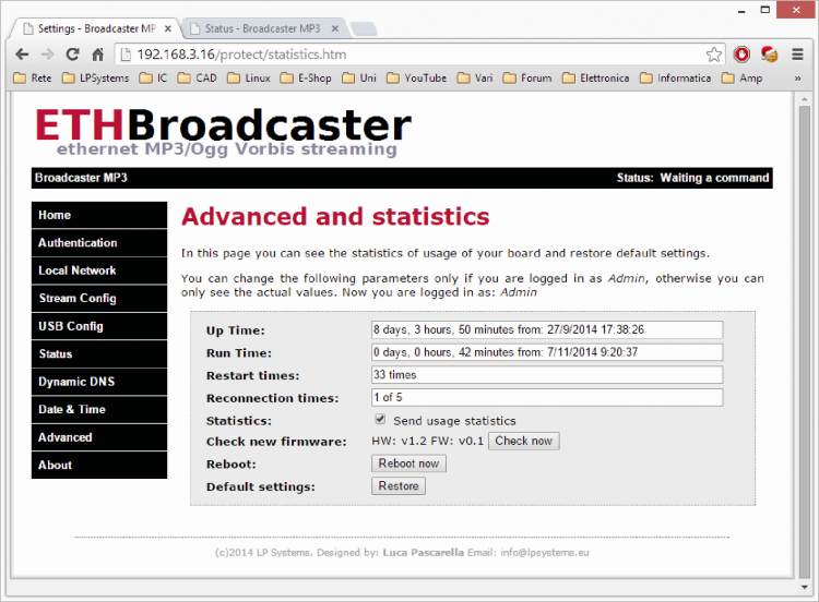
The check new firmware item shows the current firmware and hardware version and allows, using the procedure described in the next section, to update the transmitter firmware. Finally, the last two items allow you to restart the board (in 3 seconds) and to reset it to factory settings. The factory reset can also be done by holding down for more than four seconds both left and right buttons during the power on phase. A very fast blue and central-red LED blinking indicates this state. When the blue LED start blinking regularly, the board is operational again.
FIRMWARE UPDATE
Trying to give this project a long life, we have chosen to design the software into two parts, a bootloader that is factory loaded with the appropriate In Circuit Serial Programming (ICSP) programmer and an app that contains the actual functionalities supported by our board.
The bootloader is loaded in a separate microcontroller memory area and will not change unless we intervene again with the programmer. The app is installed in a rewritable memory area by the boot loader, which allows you to make firmware updates without a dedicated tool.
In this section we describe how to update the firmware, every time we want to add new features or to correct any bug. In a normal use scenario, just go through the browser to the right configuration page by clicking on the Advanced menu item. This page shows firmware and current hardware version, as shown in figure.
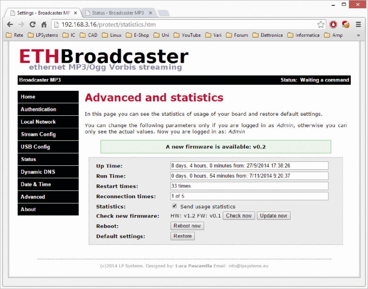
Clicking on Check now button, it will check for a new firmware version. This procedure will contact the remote server and will check for updates available for the specific hardware. If it is available, a warning message will appear as shown in figure and the Update now button gets active. Before proceeding with the upgrade you must insert a USB pen-drive formatted to FAT16 or FAT32 with enough free space (at least 10 MB), then you can proceed with the procedure by clicking the Update now button.
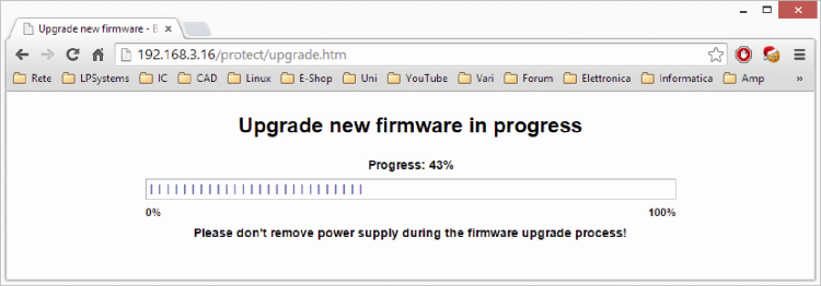
The firmware update process may take some time and it is very important not to remove the USB pen-drive or unplug the power connector: you risk freezing the board, making it unusable.
To make sure that a corrupted firmware or any error during the process could damage the board, the microcontroller will calculate the received firmware MD5 comparing it with the hash communicated by the remote server. Only when there is a perfect matching between the two hashes, the software will proceed with the upgrade by copying the files block to the microcontroller flash memory.
If not matching, the PIC will interrupt the firmware upgrade process and return an error message. During the new firmware download (stored into the usb pen-drive) the microcontroller will continue working normally and the blue LED will flash regularly; When this phase is finished, the microcontroller will start calculating the MD5 hash and this stage is signaled by red LED steady on. After verification, if everything is fine, the red LED flashes slowly; from this moment, the real firmware update process begins and it is important that the power supply is not interrupted until done.
In this phase, the bootloader will erase the old app and install the new one. When the cancellation procedure is complete, the red LED will be off and the central red LED will flash rapidly. When the blue LED will start flashing again regularly, at 1HZ, the procedure has been executed perfectly and the board will be operational.
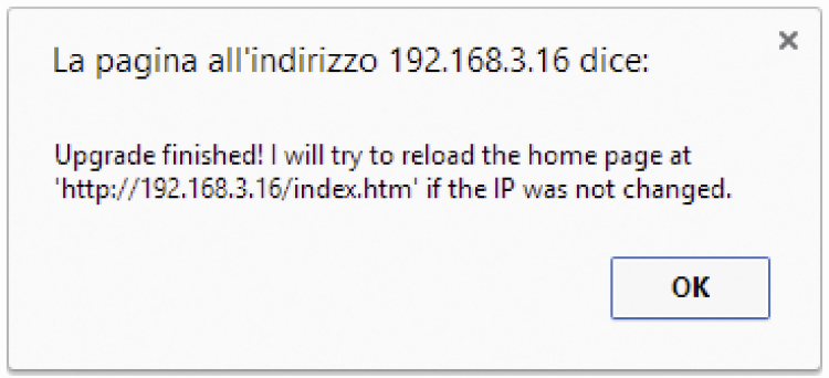
During the entire update, the management web interface will show the progresses done. The “upgrade successful” is shown by the message in figure , which will automatically be displayed when done.
If you have network problems or you can’t access to the management web page, you can upgrade the firmware manually.
In this case, we must first reset the board to factory data, by holding the left and right buttons (on the board) for more than four seconds, and then manually load the new firmware into the USB stick, renaming it exactly “image.hex”.
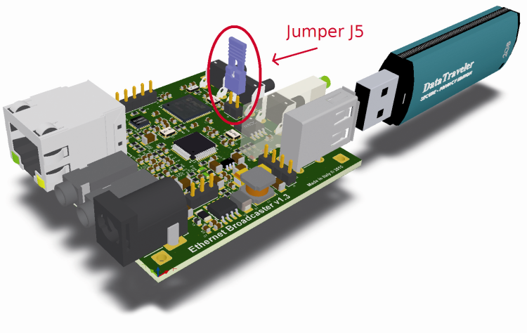
Now you must plug the usb drive to the board that is switched off after the factory reset. Set a jumper on board J5 connector, and wait for the update, which will last a few seconds and is usually indicated by red LEDs flashing.
After this stage you will need to update the management web pages, so you may need to access from the browser to the IP address assigned by DHCP; for example, the URL may be http://192.168.3.16/mpfsupload; or, if you are using a MS Windows pc with NetBIOS enabled, simply go to http: //MCHPBOARD/mpfsupload.
From the specific page, you have to select the “page.bin” for all the web pages you want to upgrade and then click Upload.

From openstore
Ethernet MP3/Ogg Vorbis Broadcaster

Hello,
Your project is very interesting. I have a website that references all hardware and software needed for the radio. Your card and its interface ” ETH Broadcaster ” seems to meet the expectations of many radio technicians.
I would like to know whether the software part can be used with a Raspberry Pi ?
If a change of the map is possible? With RCA or XLR inputs ?
Lending a card “Ethernet Broadcaster ” can be considered in order to test and write an article for website: https://technic2radio.fr ?
Best regards
I would like to have the unit and the firmware. Any ways to get this.