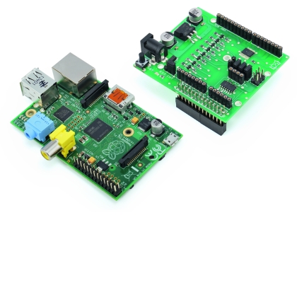
Let’s expand RaspberryPi functionalities with a shield that is compatible with the Arduino pinout and with an onboard analog to digital converter with 16-bit resolution. Further expansions that we will present in the future will allow you to add a DAC, a number of additional digital I/Os and the ability to connect also with non GPIO enabled boards.
Today we present an ADC shield that allows you to add to the possibility for a RaspberryPi to read from analog sensors. As we will see later in the article, this shield can be powered both 12V and 5V: it converts the voltage levels from 3.3V to 5V for the GPIO digital pins and the for the communication bus of i2 and SPI. In addition, this shield has both a GPIO compliant connector for RaspberryPi and the strips matching the typical Arduino microcontrollers and related shields.
Essentially, with this shield you can use RaspberryPi along with many of the already available Arduino shields or just share some pins to put a RaspberryPi and an Arduino microcontroller in communication.
DIAGRAM

The GPIO shield has been designed to offer the following options:
-
Extend the functionality of the GPIO with a four-channel differential or single ADC converter, directly on the board and, with an additional shield, with an boost to 16 additional digital I/O plus a 4096 steps DAC.,
-
using 5V RaspberryPi power supply or external 5V to 12V power supplies for compatibility with the Arduino shield;
-
Converting 3.3V with 5V, and vice versa, from the I2C and SPI digital I/O buses to meet the electrical requirements of both RaspberryPi and the external sensors and devices
-
having the possibility to use the ADC converter with inputs both in differential and linear mode
-
having a 26-pin connector to connect GPIO to RaspberryPi
-
having connectors for directly connecting an Arduino board and the future shield we are going to release;
-
having connectors for additional external USB/i2C and USB / SPI converters .
Let’s analyze the wiring diagram to see how the requirements have been put to work in practice. We can start from the power supply, consisting a classical configuration based on the 7805 regulator. The capacitors filter and stabilize the output voltage. The EXT and INT jumpers allow you to choose whether to receive the 5V supply from pin 2 of the GPIO connector or from an external controller through the 7805 regulator. In this way it is possible to avoid an external power supply, when it not necessary. Pin 2 of the RaspberryPi is capable of delivering 500 mA in the A version and and 300 mA in version B. For shields and sensors with greater absorption or with shields requiring higher voltages as, for example, the relay shield, you must use an external power supply.

Now let’s check the level conversion circuits, which are manufactured using two different approaches.
Th conversion of the levels of the digital I/O pins is done using the TBX0108 integrated, an 8-bit level shifter with two power lines.
On the A side, you’find the lines coming from the GPIO RaspberryPi connector dubbed RPI in the diagram, on the B side you see the lines connected IOL and IOH connectores, mapping Arduino I/Os. GND is connected to ground, VCCA and VCCB are the voltage references for the conversion of levels and are connected to 3V and 5V lines; OE (Enable) enables the operation of the integrated when placed at high level then is connected to VCCA (Voltage 3,3V)..
The tableshows the correspondence between the RaspberryPi’s GPIO pins and Arduino pin connectors, the two sections of the table give the correspondences for both the configuration of the rev. 1 both and of the rev. 2.
|
Arduino |
RPI rev. 1 |
RPI rev. 2 |
|
D2 |
GPIO18 |
GPIO18 |
|
D3 |
GPIO 23 |
GPIO23 |
|
D4 |
GPIO 24 |
GPIO24 |
|
D5 |
GPIO 25 |
GPIO25 |
|
D6 |
GPIO 4 |
GPIO4 |
|
D7 |
GPIO17 |
GPIO17 |
|
D8 |
GPIO21 |
GPIO27 |
|
D9 |
GPIO 22 |
GPIO22 |
In the TBX0108, voltage level conversion works in both directions automatically as the TBX0108 is able to determine the direction of data flows for each I / O pin (autosensing).
For what regards the I2C bus, SPI bus and serial port lines we choose a solution based on the BSS138 MOS- FET, N-channel field effect transistor in enhancement mode with a VGS threshold of 1.3 V.
The level conversion circuit is identical for each signal line. As an example we refer to the SDA line of the I2C bus. The gate (g) of the BSS138 MOS-FET (T7) is connected to the to 3.3 V power supply line, the source (s) is connected to the lower level signal line (3,3 V) and the drain (d) is connected to the higher level line (5V).

Let’s check now the ADC conversion for which we have chosen the Microchip MCP3428 .
In the ADC conversion we had to accept a little compromise in mapping the pins on the Arduino shield connectors. Arduino has six ADC inputs but two of these, pins A4 and A5 are shared with I2C inputs. In the Arduino environment, the different locations of the pins are programmatically configurable, according to the application. This possibility is not reproducible with the RaspberryPi, which is not natively equipped with ADC converter. In our case, we have adopted the external integrated circuit that communicates with the microcontroller via I2C, engaging related pins and leaving only four pins free for the ADC inputs. On the other hand MCP3428 allows conversions up to 16 bits of precision of both linear and differential signals.

Terminals ranging from CH1+ to CH4+ are respectively connected to pins ranging from A0 to A3 on the AD connector on the Arduino. The terminals ranging from CH1- CH4- are mounted on the A- strip, and can be grounded individually thanks to the J0, J1, J2 and J3 jumpers. In this way it is possible to configure each pin to capture both linear and differential analog signals. SDA and SCL pins are connected on one side to the corresponding Arduino connector pins and on the other side to the xxx of the Txx transistor. The Adr0 and Adr1 pin allow to assign different addresses to the integrated circuit depending on the combination of low and high levels assigned to the pin themselves. In our case we keep both pins at a low level by connecting them to ground so as to set the 0x68 address. Obviously the VCC pin is connected to 5V and VSS pin is grounded.
The serial bus lines coming from pin 8 and 10 of the GPIO connector also go to the corresponding conversion levels circuits and then to the TXD and RXD pins of the Arduino connector.
Finally, Jxx connector brings the i2C bus lines to connect an external USB/i2C converter. The same applies to the Jxx connector that brings the SPI bus to be able to connect with an external USB/SPI converter .
BOM
[code]
R1: 10 kohm (0805)
R2: 10 kohm (0805)
R3: 10 kohm (0805)
R4: 10 kohm (0805)
R5: 10 kohm (0805)
R6: 10 kohm (0805)
R7: 10 kohm (0805)
R8: 10 kohm (0805)
R9: 10 kohm (0805)
R10: 10 kohm (0805)
R11: 10 kohm (0805)
R12: 10 kohm (0805)
R13: 10 kohm (0805)
R14: 10 kohm (0805)
R15: 10 kohm (0805)
R16: 10 kohm (0805)
R17: 10 kohm (0805)
R18: 470 ohm (0805)
C1: 100 nF (0805)
C2: 100 µF 25 VL (E)
C3: 100 nF (0805)
C4: 100 µF 25 VL (E)
U1: TXB0108PWR
U2: MCP3428-E/SL
U3: MC7805ABD2T (D2PAK)
LD1: LED (0805)
T1: BSS138W-7-F
T2: BSS138W-7-F
T3: BSS138W-7-F
T4: BSS138W-7-F
T5: BSS138W-7-F
T6: BSS138W-7-F
T7: BSS138W-7-F
T8: BSS138W-7-F
D1: GF1M-E3/67A
RST: Microswitch
[/code]
USE THE SHIELD ON RASPBERRYPI
To proceed in subsequent operations, use RaspberryPi in terminal mode, the two SSH and SCP windows open and root login.
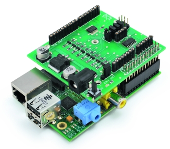
Connect the RPY connector of the shield to the GPIO RaspberryPi connector and give voltage.
Now we shall activate the i2C and SPI management modules (drivers in the Windows world) or just one of the two, depending on your needs.
The I2C and SPI management modules are compiled into the Raspian kernel as external.
To make use of one or both of the management modules you need to remove them from the blacklist and then “add” them to the set of modules known to the kernel.
Now open the configuration file that contains the list of blacklisted modules (obscured), with the command:
nano /etc/modprobe.d/raspi-blacklist.conf
Nano ia a minimalist text editor that runs on the terminal.
Erase I2C and SPI modules from the blacklist by deleting the lines or, as we preferred, just commenting with a “#.”
Press Ctrl-X and then Y to save the file after the changes.
Now we must make sure that the two modules are loaded and become an integral part of the kernel. To do this, we have two possibilities. The first allows us to load the modules on a command basis, and it is valid for the entire time the RaspberryPi stays on. At the next boot the modules need to be reloaded by a given command. The second way allows you to load the modules directly to the operating system boot and make them available immediately to applications after booting, which is essential if the server system runs unattended.
The first option requires the use of the modprobe command.
Just use:
modprobe i2c-dev
We can check the success of the driver activation with the command that displays the list of all installed modules lsmod. As in Linux everything (or almost everything) is a file, let’s go in the /dev folder and see the connection files appear for the i2c-0 and i2c-1 devices. To unload the drivers just use:
modprobe –r i2c-dev
If you want the modules to be loaded at boot you need to modify the configuration file /etc/modules, which contains the list of drivers to load at boot time.
To edit the file we can use the command:
nano /etc/modules
and add a new line to the configuration file that contains
i2c-dev
Press CTRL X and then y to save changes to the file and exit.
Now let’s install the i2c-tools package that provides us with functions you can use with command line to verify the operation of the i2c bus:
apt-get install i2c-tools
and add pi user to the i2c group:
adduser pi i2c
Then perform RaspberryPi reboot to activate the new configuration with the command
reboot
After RaspberryPi has rebooted and you have reconnected with Putty or Kitty check whether the I2C bus is visible to the ADC with the command
i2cdetect -y 0 per RaspberryPi rev. 1 oppure
i2cdetect -y 1 per RaspberryPi rev. 2
You should get a result that is similar to that shown in figure where the 0x68 address identifies the ADC.
Use this command:
i2cget –y 0 0x68 0x88 w per RaspberryPi rev. 1 oppure
i2cget –y 1 0x68 0x88 w per RaspBerryPi rev. 2
to read the hexadecimal value of the two bytes returned from channel 1 of the ADC.
The second parameter indicates the I2C bus to be interrogated while the third is the register that contains the address of the device to read (0x68). The fourth is the register which indicates the inpit from which we wish to know the digital readout and the sampling procedure, the last parameter, w, indicates that we want both the bytes of the measure.
Where to buy
You can find this shield on our store.

[…] Let's expand RaspberryPi functionalities with a shield that is compatible with the Arduino pinout and with an onboard analog to digital converter with 16-bit resolution. […]
[…] Let's expand RaspberryPi functionalities with a shield that is compatible with the Arduino pinout and with an onboard analog to digital converter with 16-bit resolution. […]
Are the PCB layout images available, especially since the commercial board is out of stock?
I’ll publish the grber file
Hi. Where I can find PCB layout for this Shield. Thaks.
[…] Expansion Shield for RaspberryPi concordant with Arduino | Open … […]
[…] Expansion Shield for RaspberryPi concordant with Arduino | Open … […]