Let’s prepare the G-code, starting from the Gerber file, so to finally print our PCB.
In the previous installment, we left you after having analyzed the hardware that enables us to manage our CNC by means of whichever modern computer that is not supplied with a parallel port (as long as it supplied with a USB connection). We seized the opportunity for an introduction of the application that we wanted to create as well, that is to say, for the creation of some PCBs, without having to resort to the traditional photoengraving process. We also took the opportunity for a presentation of the software that we will use, coupled with our USB/LPT parallel interface: grblControl. That’s a free software, created for interfacing microcontroller based boards on which the grbl firmware runs.
Actually, we need another application as well, in order to transform the regular CAD file of the printed circuit board into a file that may be suitable for grblControl, given that the electronic CADs supply the PCB’s description in a format that was born for the traditional photolithographic engraving procedures, while here we have to deal with the mechanical processing on CNC machines.
How to engrave PCBs without acid
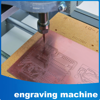
Well, we may now move on to see the core of the application, that is to say, how to build some printed circuit boards; but you won’t have to print anything, nor to photoengrave, nor to use felt-pens, films, development and acid solution. Here the PCBs will be veritably engraved, by means of a specific tool mounted on the electro-spindle.
The first thing to be done is to acquire a CAM, that is to say, a computer aided manufacturing software for mechanical elements and systems; in our case we will explain how to work by means of FlatCAM, that may be downloaded from the http://flatcam.org/ webpage.
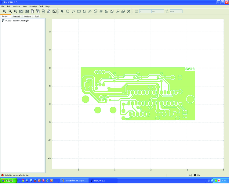
Please open the FlatCAM program, once it has been downloaded and installed; while in the start screen, please import the Gerber file you desire, by clicking on File / Open Gerber (in our case, that’s P1263 – Bottom Copper.gbr). Clearly, the Gerber file must have been prepared by means of an electronic CAD software, such as for example, Eagle (https://www.autodesk.com/products/eagle/overview) or OrCAD (or by means of many other ones that are capable of creating Gerber files).
The PCB will be shown in the FlatCAM’s right quadrant of the screen, while in the Project folder the name of the pertaining file will appear (in our case that’s P1263 – Bottom Copper.gbr).
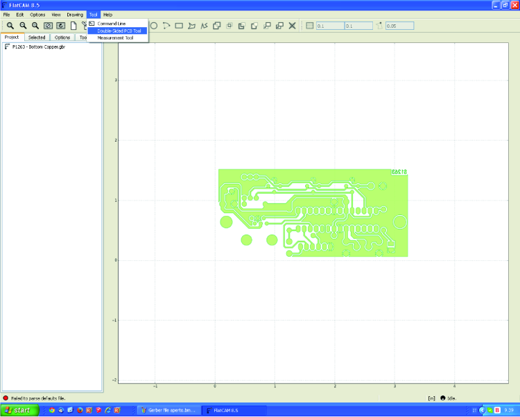
In the here described case, the PCB’s tracks are seen from the component’s point of view, however, in order to correctly carry out the engraving of the tracks on the fiberglass breadboard, it is needed to create a mirror of the PCB itself, so to be able to see it from the welding point of view.
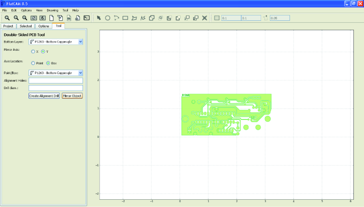
Now you will have to click on the Tool menu and to give the Double-Sided PCB Tool command; once this has been done, on the left side of the screen the Tool board will be automatically selected, from there the “Y” (as for Mirror Axis) and “Box” (as for Axis Location) entries must be checked. After that, please click on the Mirror Object button and you will see that the PCB will be rotated on the Y axis, and that it will appear exactly in the way it will be engraved on the printed side.
Please notice that the corner down and on the left is orientated towards the origin point (coordinates 00), and as shown in figure.
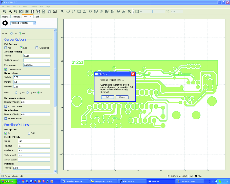
Please click now on the Options board and, while in the drop-down menu, select PROJECT OPTIONS. In this case our project has the measurements in millimeters, therefore the same unit of measurement will have to be selected (mm). Immediately, a notification window will appear, so to inform us that the whole project will be adjusted to the selected unit of measurement; please accept by clicking on OK. In this way, the grid and the whole PCB will be updated, according to the new settings.
Now, please select the Project board, the same in which the imported Gerber file is found (in this case that’s P1263 – Bottom Copper.gbr) and double click on it: the Selected board corresponding to the Gerber Object will be opened. In the Isolation Routing section you will have to specify the tool diameter (Tool dia) that is being used for engraving the tracks. Width indicates the width of the isolation created by the tool (1= the tool’s diameter) while Pass overlap indicates the overlap for each passage; the last two entries must be set according to your needs.
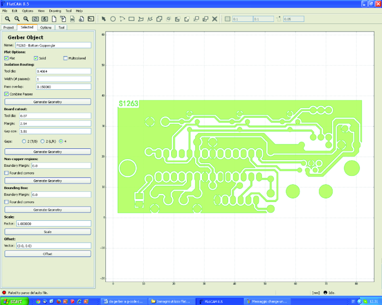
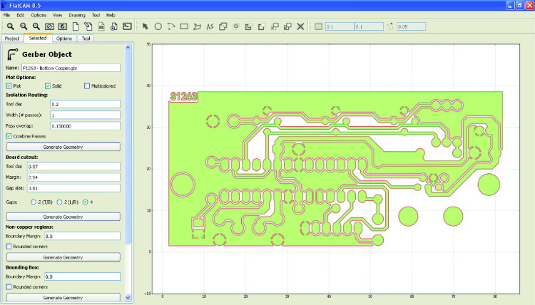
In this example a tool diameter (Tool dia) that is equal to 0.2 mm has been input, thus leaving the Width entry at 1 and the Pass overlap entry at 0.15. After having chosen the settings, please click on Generate Geometry, so to create the geometry for the contouring of the PCB’s tracks; it will appear highlighted, with a red color stroke.
You will now have to open the Project board again, in which the new xxxx_iso file (in this case, P1263 – Bottom Copper.gbr_iso) will be found; after that please double click on this file, so to open the Selected board corresponding to the Geometry Object.
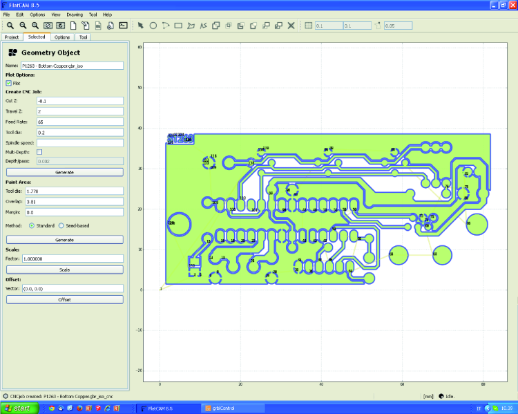
While in the board, please set the fields pertaining to Cut Z (engraving depth, for example 0.1 mm), Travel Z (tool height with respect to the breadboard being processed as for the quick movements given by the G0 commands: for example, 2mm), Feed Rate (advancement speed on the axes, as for the regular movement commands, that is to say the G1 ones: for example, 65 mm/min) and Tool dia (the diameter of the tool being used, for example, 0.2 mm).
After having set the required parameters, please click on Generate, so to create the xxxx_iso_cnc file, that will still be placed in the Project folder; the tracks’ contouring will be coloured blue, as shown in the previous figure.
Now, please go to the Project folder and double click on the xxxx_iso_cnc file that has just been created (in this case that’s P1263 – Bottom Copper.gbr_iso_cnc); the Selected folder, the one pertaining to CNC Job Object, will be automatically opened. There, you will have to type the exact diameter of the engraving tool that you will use, in the Tool dia field, after that please press Update Plot and then Export G-Code.
Once this has been done, a window will open, and you will have to specify the name corresponding to the G-code file that will be created for the tracks’ contouring, as well as the path in which it will be saved.

As for the creation of the G-Code corresponding to the drilling of the PCB itself, the procedure is a very similar one; in order to make it clearer and simpler, we imagined to start from a new project (by clicking on File / New) but nothing forbids the possibility to carry on from the previous step.
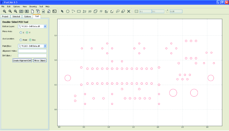
After that, please open the .drl file pertaining to the drilling plane of the PCB being processed (in this example, that’s P1263 – Drill Data.drl), by clicking on File / Open Excellon.
In the box on the right of the related dialog box, the holes of the PCB’s pads will appear; please click on Tool / Double-Side PCB Tool. The Tool board will be automatically selected, while in there you will have to check the “Y” (as for Mirror Axis) and “Box” (as for Axis Location) entries. The PCB will be rotated on the Y axis, and it will appear exactly in the way it will be engraved on the printed side.
Now, please click on the Options folder, so to select PROJECT OPTIONS and mm as unit of measurement, then please click on OK, so to confirm the modification.

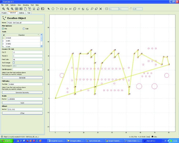
Please select the Project board, in which the .drl file is found (in this example, that’s P1263 – Drill Data.drl) and double click on this file, so to open the Selected board, that is related to the Excellon Object.
While in the Tools table, you will now have to select the first tool, and in the fields under Create CNC Job, you will have to type the values pertaining to Cut Z (drilling depth: for example -2 mm), Travel Z (tool height, with respect to the breadboard being processed, as for the quick movements: for example 2 mm) and Feed Rate (advancement speed: for example 40 mm/min).
After having typed the parameters, you will have to click on Generate.
In the quadrant on the right, all the holes that will be made by means of the selected tool will be highlighted (N°1), the path that the electro-spindle will carry out and the drilling sequence. By means of this operation, a new XXXX.drl_cnc file is created in the Project folder (in this case, that’s P1263 – Drill Data.drl_cnc).
You will now have to double click on this new file, so to open the Selected board, that is related to the CNC Job Object. After having set the diameter of the drilling tip, you will have to click on Export G-Code, as soon as a window will appear; while in there, you will have to specify the name to be assigned to the file containing the G-Code (for example P1263 g-code DRILL 1) to be created (so to carry out the drilling of the PCB pads), as well as the path in which to save it.
The procedure that has just been described enabled the creation of the G-Code pertaining to the first drilling tool provided for by the Gerber (and saved with the P1263 g-code DRILL 1 name). Since in this case the PCB needs holes having different diameters, you will need to open again the Selected board and, while in Excellon Object, to select the second tool that you will use. You will then have to repeat the same operations that have been described before, until the G-Code for this second tool is generated (you might want to save the file, for example, with a name such as P1263 g-code DRILL 2, so to distinguish it from the first one). The same procedure will have to be followed for all the remaining drilling tools that are found in Excellon Object‘s list.
Engraving and drilling PCBs by means of the grblControl software
Well, now that we have the files, we are ready to start engraving: let’s go to the machine and connect the USB/parallel converter for the CNC to a free USB port on the PC on which we are running grblControl. Windows will detect the new hardware and install the corresponding driver; if some problem occurs and the installation does not reach a successful conclusion, you will have to manually operate from Windows Device Manager.
Once the hardware installation has been completed, you will have to click on START/Control Panel/System/Hardware/Device Manager and verify that a new COM port – that is associated to the board – has been created. Please write down the port number because you will need it shortly.
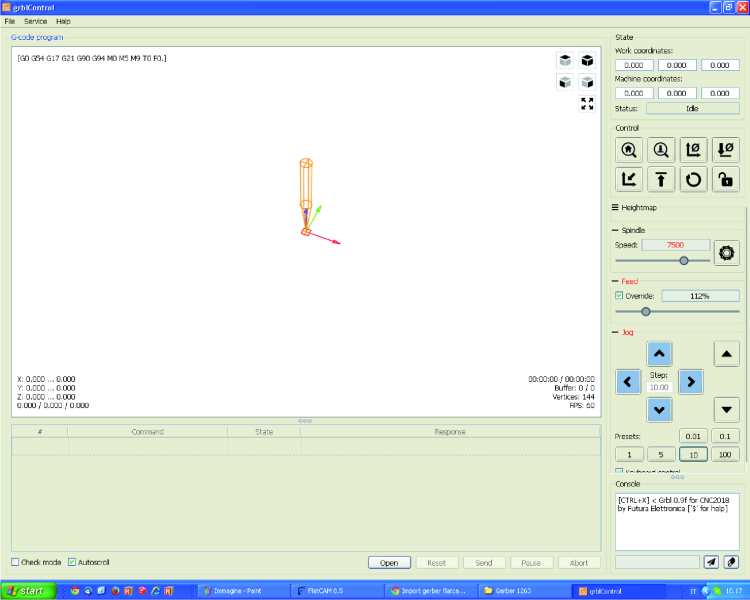
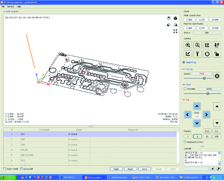
You will now have to open the grblControl program, that will appear with a screen such as the one in figure; please click on the Service menu and give the Settings command from here: a new window for the settings will open, from which to select the virtual COM port that has been assigned to the USB/parallel board (in the example, that’s COM28) and the corresponding communication speed (115200 Baud).
In the settings’ dialog box you will, therefore, have to set the following values:
Safe Z = 10
Rapid speed = 500
Acceleration = 25
Report units = Metric
Once these settings have been chosen, please click on OK, so to confirm them, and so to exit the said dialog box.

Please click now on the File menu and, from there, give the Open Gerber command; then, while in Tipo file select All files and then select the G-Code file corresponding to the contouring of the PCB tracks that you wish to carry out (for example, P1263 – g-code iso).
In the central box the outline of the PCB’s tracks will be shown, and the (orange-colored) tool that has been placed over the (blue-colored) vertical axis.
By means of a double-sided tape, you will now have to fix the fiberglass plate – with the printed side upwards – to the centre of the CNC pantograph’s worktable; please make sure that the breadboard is perfectly even with the plane (and on the same plane of the electric tool’s tip).
Please notice that, in order to avoid damaging the CNC pantograph’s worktable (and especially during the drilling), it is advisable to fix a 3÷4 mm thick masonite (or faesite) panel under the breadboard; such a panel must be perfectly even on the plane and have a regular thickness.
Please insert and block the chisel for the engraving in the electro-spindle’s clamp, the chisel must have a tip that is exactly the same that has been defined during the creation of the G-Code for the PCB tracks’ contouring (it is recommended to use a hard metal chisel, since fiberglass is highly abrasive!) and you must let it stick out only for what is strictly necessary, in order to avoid vibrations and excessive run-outs.
Please use the arrow keys – while in the Jog box – in order to physically move the electro-spindle (and therefore, the tool) in a point of the breadboard that will be considered as the origin for the PCB that you wish to engrave (as for the movements please choose the default movements – the ones named Presets – that are the most appropriate ones, or set a value in the Step box).
Once this has been made, you will have to click on the Zero XY button of the Control quadrant (indicated by two arrows and Ø) as soon as the X and Y coordinates have been reset in that spot.

After having set a Preset or an appropriate Step (we recommend choosing a low value, in order to avoid breaking the tool) you will have to click on the GIU arrow in order to lower the machine’s Z axis, and so to get the chisel’s tip as close as possible to the PCB’s printed side.
You may now restart the electro-spindle, by clicking on the Spindle on/off button (the one having a milling machine as a symbol) that is found in the Jog box. Please lower the Z axis up to the point in which the chisel touches the printed side, by means of the rotating tool and with a movement of 1 hundredth of a millimeter (Preset 0,01).
At this stage you might consider the relative position as the zero coordinate for the Z axis; in order to carry out the reset you will just have to click on the Zero Z button in the Control quadrant (it is indicated by one arrow and Ø).
After having verified that all the Work coordinates are set to zero, please raise the tool for a pair of millimeters, then stop the electro-spindle by clicking again on the Spindle on/off button, found in the Jog box.
In order to start engraving the tracks, you will have to click on the Send button that is found in the screen’s lower part; please notice that now the RUN button will become green.

It is possible to change the processing advancement speed at any time: for the purpose you will have to select Override in the Feed box, and then act on the slider, so to increase or decrease the advancement.
At least for the first times (in which you will have to evaluate the CNC operations), we advise you to carry out only some small variations, in order to avoid damaging the tool.
In order to pause the work, you may click on the Pause button, found in the lower part of the grblControl screen; if for some reasons (for example, you realise that the PCB is not turning out in the way you expected) you want to stop the processing, you will then have to click on Abort.
At the end of the engraving of the tracks forming the PCB, the electric tool will position itself at the following coordinates: X=0, Y=0 and Z= at the safety value that has been set at the creation of the G-Code.
If you expect to carry out the drilling as well, please do not remove the breadboard and do not change the tool’s position as for the X and Y coordinates; in order to carry out the PCB drilling, please follow the same procedure: this time you will have to import the G-Code for the drilling plane, and use a tip having the same diameter that has been set during the creation of the G-Code at issue. In order to avoid damaging the CNC’s worktable, we again advise keeping a 3÷4 mm thick masonite (or faesite) panel under the breadboard.
At the end of the processing, a message such as the one shown in figure will appear.

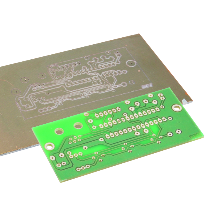
Well, you have now created your first mechanically engraved PCB! Congratulations!
From openstore
CNC mechanics – kit 200x180x60
Spindle motor 36 Vdc – 300 watt
Set board 3 axes + accessories
Switching power supply Mean Well 24 Vdc 150 W
Bipolar stepper motor NEMA 17 – 1,5 A
