
Here we complete the overview of the free 3D modeling and editing software by creating modular models that can be assembled together.
OpenSCAD is a free 3D modeling software whose strength is the capability of creating more “technical” rather than “artistic” objects, those requiring precise measurements, well-defined geometries and obtainable by repeating or replicating similar components.
In the previous tutorial episode we have seen that OpenSCAD describes objects from its basic primitives such as boxes, spheres and cylinders, using set operations (unions, intersections …) and geometric transformations. Limiting ourselves to primitive and simple operations, we had created a parametric box suitable for housing electronic circuits. In this second and final episode we’ll build something more complex: a mechanism with gears and a structure to enclose and support them.
Differently from the previous examples, this time we’ll not print the box in a single piece but in separate parts; then we’ll assemble and interlock them together.
This exercise is aiming at seeing different modeling methods first, but also at learning how to organize parts in the printing area for a most efficient and robust 3D printing.
Libraries
First, let’s create a lib/sizes.scad file where we will put the dimensions used in the project: in this way you can share them between different project files, so that you can easily change them during the exercise.
The final file output is in Listing 1, but we will fill it in step by step during this exercise.
Listing1
// Gears settings
gears_circular_pitch = 200;
gears_bore_diameter = 3;
gears_hub_diameter = 7;
gears_thickness = 5;
gears_hub_thickness = 10;
gears_rim_thickness = 8;
gears_number_of_teeth_big = 39;
gears_number_of_teeth_small = 9;
// Axis settings
axis_cylinder_r = 4;
axis_cylinder_h = 10;
axis_cube_l = 5.6;
axis_cube_h = 10;
// Handle settings
handle_d = 40;
handle_r1 = 16;
handle_r2 = 10;
handle_h = 5;
handle_hole_h = 15;
tolerance = 0.5;
handle_knob_r = 6;
handle_knob_h = 20;
// Box sizes
gears_d = gears_circular_pitch * (gears_number_of_teeth_big + gears_number_of_teeth_small ) / 360;
gears_h = gears_circular_pitch * gears_number_of_teeth_big / 180;
gears_len = gears_circular_pitch * gears_number_of_teeth_big / 180 + gears_d;
gears_width = gears_rim_thickness * 2;
box_wall = 2;
box_length = gears_len + 10;
box_width = gears_width + axis_cylinder_h - box_wall + 1;
box_height = gears_h + 10;
box_clear = 0.15;

This file will be included in all files using the instruction: include <lib/sizes.scad> (Listing 2)
equivalent, logically, to copying and pasting the lib/sizes.scad content where the instruction is put; This way we can use the variables defined in lib/sizes.scad library everywhere.
Pay attention to the fact that the include statement should not be used within modules or instruction clusters, since a library inclusion in that point could cause a syntax error.
In general, it is a best practice to use “includes” to split big software projects into smaller and easier to be managed parts; by creating lib files, you make it easier to reuse code lines everywhere, like sharing global variables in our case.
Going further, it will happen that you would create modules reusable in multiple projects: these modules can be collected in a file to be included in other projects, creating a real personal or shared on the Internet “library”.
The main box sides, long_side.scad and short side.scad are simply designed as a union of cubes from which other smaller cubes will be removed to form the interlocking. The box_clear value is used to add a tolerance (clearance) to the joints, and obviously depends on the characteristics of the printer used.
Listing2
include <lib/sizes.scad>
module axis() {
difference() {
union() {
cylinder(r=axis_cylinder_r, h=axis_cylinder_h);
translate([-axis_cube_l/2, -axis_cube_l/2, axis_cylinder_h - 0.01])
cube([axis_cube_l, axis_cube_l, axis_cube_h]);
}
translate([0, 0, -1]) cylinder(r=gears_bore_diameter/2,
h=axis_cylinder_h+axis_cube_h+2);
}
}

Third-party libraries
Besides the ability to create your own “parts library”, OpenSCAD allows to include all the libraries found on internet to our project. One of these is MCAD, distributed with OpenSCAD, that includes useful parts to make mechanical models; we will use a part of that library to make a couple of toothed wheels.
To use MCAD in our gear.scad file we will use the instruction use <MCAD/involute_gears.scad>. The difference with include seen before is that use imports the definition of modules only, but ignores any instruction to draw objects (see Listing 3). This allows libraries authors, for example, to have a test object within the file to verify that everything works fine, without this being included in all projects that link the library. We can see that the command use <MCAD/involute_gears.scad> works even if the MCAD directory is not present in our project: when you use includes and use, OpenSCAD looks for files in three possible locations, in order:
- in the project directory;
- in OpenSCAD installation folder;
- in user libraries directory, whose address is visible from File → Show Library folder menu …
Listing3
 use <MCAD/involute_gears.scad>
include <lib/sizes.scad>
$fn=32;
union() {
gear(
number_of_teeth=gears_number_of_teeth_big,
circular_pitch = gears_circular_pitch,
bore_diameter = gears_bore_diameter,
hub_diameter = gears_hub_diameter,
thickness = gears_thickness,
hub_thickness = gears_hub_thickness,
rim_thickness = gears_rim_thickness
);
translate([0, 0, gears_thickness - 0.01]) gear(
number_of_teeth=gears_number_of_teeth_small,
circular_pitch = gears_circular_pitch,
bore_diameter = gears_bore_diameter,
hub_diameter = gears_hub_diameter,
thickness = gears_thickness,
hub_thickness = gears_hub_thickness,
rim_thickness = gears_rim_thickness * 2 - gears_thickness
);
}
In this case MCAD is in the OpenSCAD directory and can be referred to without having to do anything.
involute_gears.scad defines a gear module with numerous parameters that we can simply use to make our gear parts.
To improve the OpenSCAD drawing precision for fine details requested by our gear components, we will use the $fn=32 special variable; this means that arcs will always be drawn so that a complete circle is made by 32 segments. The central gear part, gear.scad, consists of two toothed wheels with 39 and 9 teeth, one over the other. As seen in the previous episode, the second gear is shifted by a bit less than the thickness of the first, to define intersections correctly.
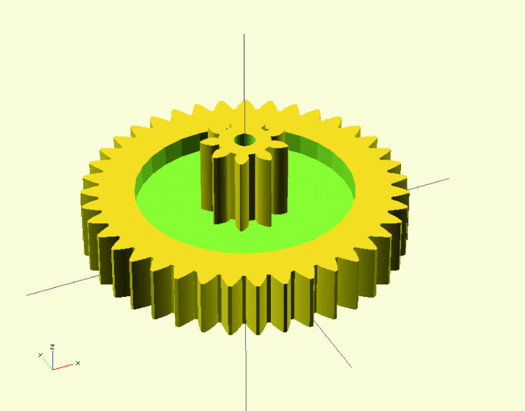
Unfortunately, due to a known bug that the involute_gears.scad library has in the calculation of generated gear size, the circular_pitch parameter does not really correspond to the distance between two teeth; the gear diameter is erroneously calculated by the number of teeth (* circular_pitch / 180). In reality, the actual distance between teeth is circular_pitch * π / 180.
Modules
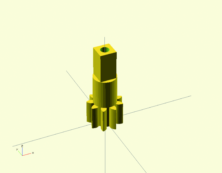
The other two gear parts, gear_small.scad and gear_big.scad are equal to one of the two main gear wheels, but they have a central square hole designed to insert the handle we’ll model later (or anything else we want to use to move the wheels).
Since the insertion is the same in both models, we can define it in a separated file to be used as our personal library: as in the previous article, let’s define an axis() module, this time without any parameters, and save it as lib/axis.scad.

Advanced transformations
To make the typical handle shape, in handle.scad files let’s use the convex hull of two cylinders, explained later in this article. In the measures file we have also specified a different tolerance (not the one needed for the box sides interlocking), to adapt the model better to the characteristics of the printer or method by which you will create the physical model, to allow the crank to fit properly in the square attack (see Listing 4).
Listing4
include <lib/sizes.scad>
$fn=32;
hole_l = axis_cube_l + tolerance * 2;
difference() {
union() {
hull() {
cylinder(r=handle_r1, h=handle_h);
translate([handle_d, 0, 0]) cylinder(r=handle_r2, h=handle_h);
}
cylinder(r=hole_l, h=handle_hole_h);
}
translate([0, 0, handle_hole_h/2])
cube([hole_l, hole_l, handle_hole_h + 2], center=true);
translate([handle_d, 0, -1]) cylinder(r=1.5, h=handle_r1 + 2);
}
To model the knob (Listing 5) we could use a simple cylinder, but rounding the top end through a Minkowski sum with a hemisphere (see details below) to have a more comfortable grip.
Listing5
include <lib/sizes.scad>
$fn=32;
hole_l = axis_cube_l + tolerance * 2;
difference() {
minkowski() {
cylinder(r=handle_knob_r - 1, h=handle_knob_h - 1);
difference() {
sphere(r=1);
translate([0, 0, -1.1]) cube(2.2, center=true);
}
}
translate([0, 0, -1]) cylinder(r=gears_bore_diameter/2, h=handle_knob_h + 2);
}

Dxf extrusion
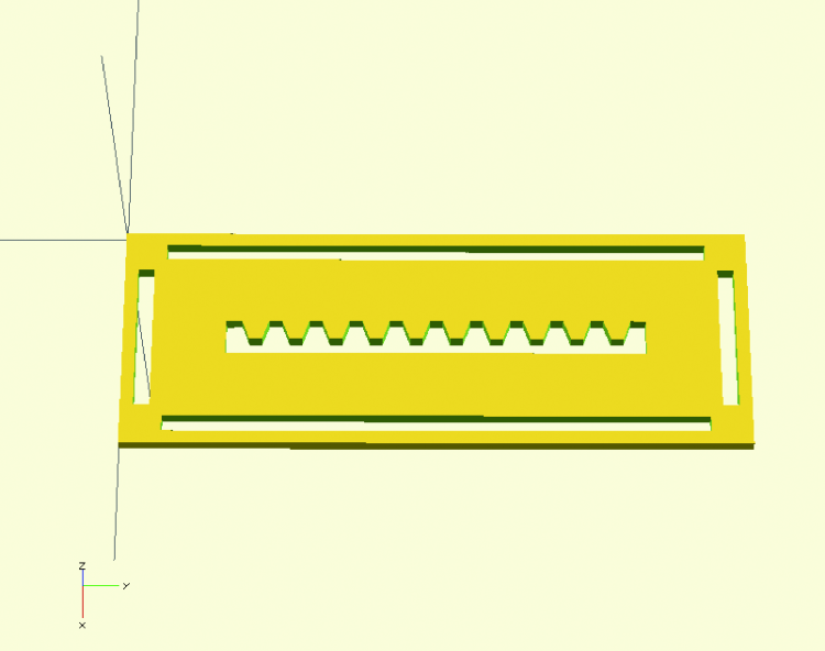
The base (base.scad file) is built like the walls, i.e. composing cubes, but we want to add to the upper side some decorations .

To do this, first we define the base as a module, referring it at the end of the file, so we can use the same definitions in top.scad file.
Now that the gears size has been well defined, we use two echo instructions to print the calculated box dimensions; we will see the result in the lower right OpenSCAD window, along with system messages:
ECHO: 80
ECHO: 25
With a vector graphics software or CAD, let’s prepare a canvas of that size, top.dxf (we used Inkscape, as explained in the box above), then we import it as a two-dimensional surface with import command. Finally, we can extrude it to have a three-dimensional object we can remove from the box. Our model is ready; now we can print all the pieces, prepare two wires of suitable length to be used as axes and assemble our gear, choosing which side to mount the crank according to the desired ratio.
Advanced transformations
In the first episode we saw how the elementary models of OpenSCAD are handled through transformations with which they can be translated, rotated or changed in size. OpenSCAD offers more complex transformations, including “Minkowski” and “hull” too.
Using these transformations and working on complex models when using slow computers can cause OpenSCAD not be able to complete a compilation resulting in interface freezing: in these cases, just run the compilation by the command line.
Minkowski addition
In mathematics, the Minkowski sum of two sets X ⊂ ℝ ⁿ and Y ⊂ ℝ ⁿ is defined as the set {x + y: x ∈ X, y ∈ Y}, i.e. of each pair of points taken from the two initial sets you do the vector sum and the result is a member of the resulting set.
If one of the two sets is centered at the origin, as is in most cases, you can see the final result as the application of this solid to all the other solid points, the “base” solid.
As an example, you can calculate the offset of an object, i.e. widening an object of a certain amount from the original; to enlarge it in all three dimensions you shall make a Minkowski sum to a small sphere (or to simplify calculations, with a small cube). If you want the offset of a two dimensional surface, you simply shall sum it to a small circle.
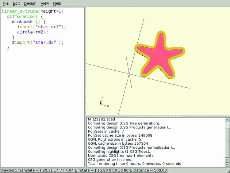
For example, in figure we imported a two-dimensional star from a .dxf file, we have calculated the extrusion by summing a circle to it, we removed the original star (shown in red through the # modifier) and then we made again an extrusion of the only boundary.
linear_extrude (height = 1) difference () {
Minkowski () {
import ( "star.dxf");
circle (r = 2);
}</em>
# Import ( "star.dxf");
}
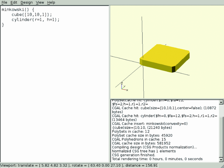
Another application of the Minkowski sum is to obtain shapes with rounded edges; for example, making the sum of a parallelepiped and a cylinder we can obtain a plate with rounded corners:
Minkowski () {
cube ([10, 10, 1]);
cylinder (r = 1, h = 1);
}
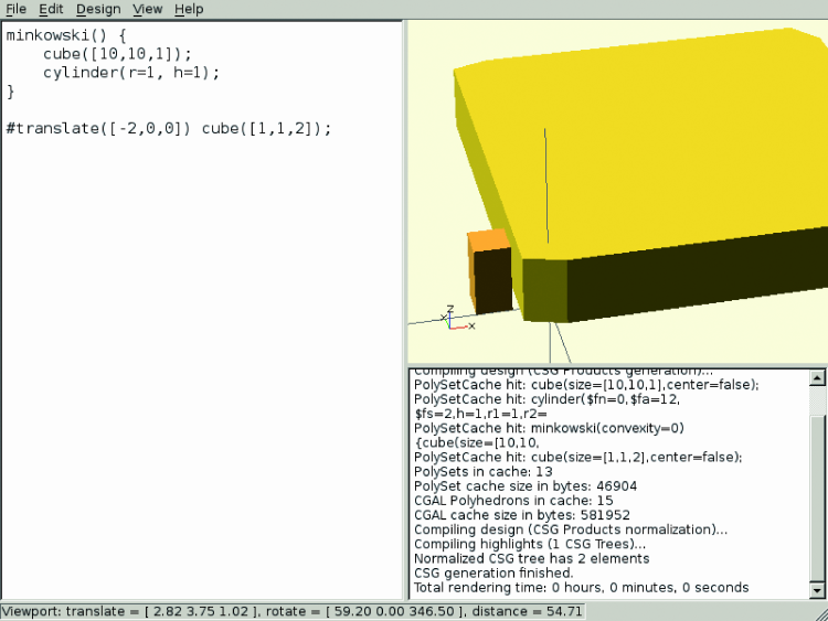
One thing to watch out is that this transformation enlarges the original object: for example, by comparing the plate above with a 1x1x2 cube, we see that the final height of the object is the sum of two heights (since the objects we added were flat), and that also other dimensions are grown:
Minkowski () {
cube ([10, 10, 1]);
cylinder (r = 1, h = 1);
}
# Translate ([- 2, 0, 0]) cube ([1, 1, 2]);
Convex hull
The convex hull of one or more solids is defined as the smallest convex solid that contains all of them.

This transformation is made available in OpenSCAD with the command hull and it can be used, for example, to describe a bit more complex forms than the usual ones. In figure we did a hexagon with rounded edges, specifying cylinders (marked in red) that describe the corners and asking OpenSCAD to calculate the “inside”. The code is as follows:
hull () {
for (i = [0: 5]) {
rotate ([0, 0, i * 60]) translate ([10, 0, 0]) cylinder (r = 4, h = 3);
}
}

for (i = [0: 5]) {
rotate ([0, 0, i * 60]) translate ([10, 0, 0]) #cylinder (r = 4.01 h = 3.01);
}
Another practical application of this transformation can be to build a basis for elements disposed at known positions, but not easily described with one of the elementary solids, maybe then adding an offset with Minkowski.
For example, in figure is seen a base with fastening holes in a list of arbitrary positions, defined as:
positions = [
[40, 2, 0],
[-10, 7, 0],
[0, 30, 0],
[20, 10, 0],
[30, 27, 0],
];

difference () {
linear_extrude (height = 2) Minkowski () {
circle (r = 3);
hull () {
for (i = positions) {
translate (i) circle (r = 2);
}
}
}
for (i = positions) {
translate (i) cylinder (h = 5, center = true);
}
}
How to use OpenSCAD from the command line
Besides the graphical interface, OpenSCAD can be used from the command line; this is not only useful in case when models are too complex and can cause issues to the graphical interface, but also it is a practical option to automate the compiling of several models (or maybe variations of the same), or to delegate the compiling to a more powerful computer than the one on which you are working.
To use OpenSCAD with CLI and not with the GUI, simply use the -o option:
OpenSCAD -o destinazione.stl sorgente.scad
In this way OpenSCAD compiles the file sorgente.scad without launching the graphical interface and saves the result in destinazione.stl, choosing the format based on the file extension.
Especially useful for the compilation of parametric models is -D option, that overwrites the constants values used in the file; For example, if you have a file that uses x and y variables to describe the width and length of a piece, you it can specify these measures with:
OpenSCAD -o destinazione.stl -D x=60 -D y=20 sorgente.scad
In particular, this option can be used in shell scripts (Linux or OSX) or in a Windows batch files to generate multiple versions of the same piece; an example shell script is:
for x in 20 40 60; do

 for y in 30, 50; do

 openscad -o destinazione-${x}x${y}.stl -D x=$x -D y=$y sorgente.scad

 done

done
This will generate the six destination-20×20.stl, destination-20×30.stl etc… files, with our model in different dimensions. The value specified with -D may include arbitrary OpenSCAD expressions; if you want to use strings you must be careful to enclose them in quotes and ensure that the quotes are not intercepted by the shell. For example, if you have a OpenSCAD file that imports the contents of the file variable you can use:
OpenSCAD -o dest.stl -D ‘file=”nomefile.dxf”‘ sorgente.scad
From openstore
3DRAG – 3D Printer dual extruder – KIT
Expansion set for printer 3Drag

good article