
Let’s step into the word of analog-digital conversion for Arduino, by discovering how the dedicated pins work and how to use them for acquisitions. Part one.
In the ADC of Arduino, an analog signal ranging from 0 to 5 V is translated in 10-bit code, which is 210 = 1024 combinations, with a number from 0 to 1023. To this regard, we must say that when we calculate “resolution”, i.e. the minimum value of our 10 bit scale, we are doing it dividing voltage by the 1024 values of the 10 bit code; when we calculate “range”, therefore the entire measurement range of the converter, we must keep in mind that the 1024 points also include the 0, therefore they go from 0 to 1023. This means that starting for instance from a 5 V power, a resolution will be 5 V/1024, which is 0,004883 V, while the range will go from 0 V to,004883 x 1023, which is 4,995 V. This means that the starting 5 V value is over-range.
However, we must keep in mind that, although we are using several decimal values in this examples, in reality, the precision of Arduino software system does not allow to currently use more than two, therefore from this point on we will always round up the results at the second decimal figure; so, for instance, value 0,004883 V would become 4.88 mV, or the math would be hard to manage.
Many Arduino users, when they have to use analog signals, especially when the amplitudes are bigger or in anyway different than the standard 5 V voltage, are faced with serious interfacing problems. More than one, inevitably, will damage the ATmega328P microcontroller because they will apply signals of greater amplitude to the pins compared to the power voltage, which is 5 V.
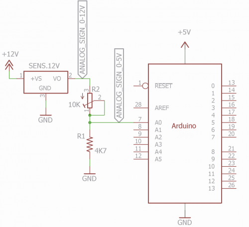
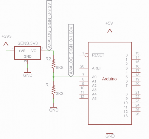
For these reasons, we decided to fully investigate the subject, enhancing the operational explanation of ADC and ARef of Arduino by practically creating a resistive voltage divider, fixed or variable, using simple but precise formulas; we will also mention some analog sensors, by illustrating a typical application.
The six pins of Arduino connected to the internal ADC are called A0÷A5 and correspond to physical pins 23÷28 of ATmega328P.
Let’s start by saying that many beginners erroneously think that these pins are bidirectional and can be turned into DAC outputs if needed, therefore in as many digital/analog converters; this is absolutely not the case! These pins are normal digital I/O pins (and to this purpose they are numbered 14÷19), therefore they can be used both as input (command digitalRead) and output (command digitalWrite), they can act as ADC input when used in combination with the command analogRead. This means, in practice, that by using an internal MOSFET, those pins are converted into inputs for the A/D converter.
Arduino also has six additional digital pins (3, 5, 6, 9, 10, and 11 corresponding to physical pins 5, 11, 12, 15, 16 and 17) which, as needed, can act as PWM generators (Pulse Width Modulation) through the command analogWrite. shows the pins related to the ADC.
In this project will only focus on the ADC functionality. In the box Successive Approximation Register ADC you can find more details regarding the type of ADC used by the AVR microcontrollers by Atmel, which is the one obtaining the value for successive approximation (there are also other types of A/D, but they are beyond the scope of this tutorial).
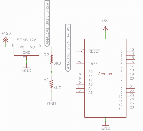
We remind you that not always an analog source generates variable voltages within the same power range of Arduino, quite the contrary, sometimes we deal with greater voltages (for instance those provided by the sensors powered by 12 V) and sometimes they can be lower (this is, for instance, the case with some integrated amplifiers for K-type thermocouples generating voltages of ~ 1 V at 100°C). In the first case, we might damage the microcontroller, while in the second case we have a low resolution (meaning imprecise measurements) and poor dynamics (which increases exposition to noise).
ARef and analogReference()
In order to adapt the measurement range, Arduino provides a pin called Aref (corresponding to physical pin 21 of the ATmega328P) and a software command analogReference(); let’s see what they are for and how to use them. ARef is the reference voltage used by the ADC to set the measurement scale, i.e. the voltage value corresponding to value 1024. The command analogReference() involves the three parameters described below.
DEFAULT
It is the end scale voltage reference and the one for Arduino’s power, which is 5 V. If we consider the 3,3 V Arduino versions or reason a possible standalone use of ATmega328P, the DEFAULT parameter clearly takes this new voltage value. By using the command analogReference(DEFAULT) on the Aref pin, we can find the same power voltage value, and that voltage might in fact be used as the reference for analog measurements, provided that the circa 30 mA of this pin are enough. This parameter is generally used for measurements where there is no need for high precision, just because it is tightly connected to the power voltage value which, if not perfectly stable and precise, might generate undesirable results. In practice, by leaving the DEFAULT value with a power voltage of exactly 5 V, a 2.5 V signal would give a value equal to 1024/5V x 2,5V=512; if voltage would then drop to 4.9 V, the same to 2.5 V signal would give a reading value of 1024/4.9 V x 2,5 V= 522. By using the DEFAULT parameter, reading resolution is
Resolution = VReference / 1024
Where Resolution represents the value in millivolts (mV) of each of the 1023 decimal points returned by the microcontroller after reading an analog voltage; VReference is the reference voltage provided by the ADC of Arduino which, in this case, corresponds to the power voltage of Arduino(5 V or 3,3 V). In case of 5 V we have: 5 V/1024 = 0,004883 V, so each point of the 1-1023 range corresponds to 4.88 mV (0 is, of course, equal to 0 V). In the configuration we use to prepare the sketches we have measured a VReference of 5.14 V. As we said, this value is easy to measure on the Aref pin of Arduino and, once we know that, we can assign it to a constant in the sketch, in order to increase measurement accuracy.
INTERNAL
In this case, the reference tension for the end scale is set at 1.1 V regardless of the power voltage. The command analogReference(INTERNAL) is generally used when Max value of analog voltage is next to 1 V or when we want to avoid possible influences of voltage variation of Arduino on the reading values (e.g., battery power). In this case, the resolution becomes 1.1V/1024=0,0011V, so each point of the 1-1023 range corresponds to 1.1 mV. In this case, also, Aref pin reports that voltage value, which can be used as the reference, and this gives a clear advantage since we don’t have to use external voltages (typically, integrated circuits symbolized by direct voltage).
We have to mention that the datasheet for ATMEL ATmega328P strongly suggest using an uncoupling capacitor (ideally a multilayer 100 nF capacitor) between Aref pin and GND, in order to make the voltage more stable and immune to disturbances (the subject will be better explained in the paragraph below); note that Arduino MEGA models have two different options for the INTERNAL, which commands are;
– analogReference(INTERNAL1V1) for the internal reference of 1.1 V, which behaves exactly like the command we have seen above;
– analogReference(INTERNAL2V56) for the internal reference of 2.56 V, in this case resolution becomes 2,56V/1024=0,0025V, so each point of the 1÷1023 scale corresponds to 2.5 mV;
We must be extremely careful when we activate the INTERNAL reference, and make sure that no power source is connected to Aref pin, in fact the two voltages would short-circuit and damage the ADC.
EXTERNAL
With the command analogReference(EXTERNAL) Aref pin, becomes an input, in fact now we are going to apply an external voltage that becomes the end scale reference. Arduino’s reference correctly suggests that we must not apply negative voltages to Aref pin, or voltages greater than 5 V, or there is the concrete chance to damage the microcontroller! This option allows you to define an extremely precise range that could also be the standard 0÷5 V, only in this case we used a very stable reference voltage and therefore measurements will also be more reliable. Then, there are specifically integrated regulators, which are very stable, and capable of providing direct voltages, that can be used in such cases. By applying a stable voltage to the Aref pin, this automatically becomes the new end scale for Arduino’s ADC. Supposing to apply a stable 2.7 volt voltage to Aref (VReference), we would have a Resolution = 2.7V/1024=0,002636V, so each point of the 1-1023 scale would correspond to 2.64 mV. In this case also, maybe even more so, it is recommended to use a 100 nF capacitor place between ARef and GND.
Now, let’s see what happens to readings of analog signals when their range corresponds exactly to the ADC reference; in other words, let’s suppose we have to measure an analog signal ranging between 0 V and ARef (according to various parameters).
The formula allowing us to calculate the decimal value for a certain measure voltage, relative to the reference voltage, is:
DecimalReading = 1024/VReference x VAnalog
As already explained, the possible coincidence between VReference and VAnalog would give an over-range (1024).
From that formula, we can also extract the inverse formula, which is very useful when we have a value read by Arduino, and we want to get the voltage applied to the analog input:
VAnalog = DecimalReading /1024 x VReference
or (since Resolution is equal to VReference/1024):
VAnalog = DecimalReading * Resolution
ADC measurement example
Now, let’s see some example of measurement of analog signals, considering 5 V for Arduino’s power and different ARef parameters.
# 1: 5 V Power, DEFAULT Reference
Using the formulas above, if we apply 1 V to the analog pin we will get a reading of: 1024/5Vx1V=204.8, obtained as
DecimalReading =1024/ VReference x VAnalog; to value is simply rounded to the closest integer, which is 205 in our case.
If we apply a 3.8 V voltage, we will have 1024/5 V x 3.8 V = 778.
If Arduino reads a value of 615, it means that, on the analog input, there is a voltage of 615/1024 x 5 V = 3.00 V (i.e. VAnalog= DecimalReading /1024 x VReference). Same result can be obtained using the alternative formula 615 x 0,004883 V = 3.00 V (VAnalog = DecimalReading x Resolution).
# 2: 5 V Power, INTERNAL Reference
In this case we are not interested in the power, as for reference, as seen above, it is fixed at 1.1 V; obviously, we can only apply voltages ranging from 0 to 1.1 V to the analog input.
If we apply a 0.25 V voltage, we will have 1024/1,1V x 0.25 V = 233.
If we apply a 0.26 V voltage, we will instead have 1024/1.1 V x 0.26 V = 242.
Please note how a difference of just 10 mV can shift the reading of 9 points, in fact, the resolution is slightly more than one 1 mC (1,1V / 1024 = 0,0011V).
If Arduino reads a value of 615, it means that, on the analog input, there is a voltage of 615/1024 x 1,1V = 0.66 V.
This example makes very clear how the same decimal value provided by Arduino during grading doesn’t absolutely translate in the same voltage value applied to the analog pin, in fact everything depends on the reference voltage.

# 3: 5 V Power, EXTERNAL 3.3 V Reference
In this case, also, we are not tied to the power value of Arduino (except for the “mini” family, where the end scale is provided by the 3.3 V which we are evidently providing to the microcontroller through the ARef pin. In this case, also, the reference decides what is the maximum voltage value pliable to the analog pain of Arduino, i.e. 3.3 V.
If we apply a 0.25 V voltage, we will have 1024 / 3.3 V * 0.25 V = 78.
If we apply a 0.26 V voltage, we will have 1024 / 3.3 V * 0.26 V = 81.
In this case, we can see how resolution notably decreases in terms of accuracy, in fact, now it is around 3.3V/1024 = 0.0032 V or 3.2 mV; only 3 points/reading separate 0.25 V from 0.26 V.
If Arduino reads a value of 615, it means that, on the analog input, there is a voltage of 615 / 1024 * 3.3 V = 1.98 V.
The classic samples proposed have been used to run some tests using the formulas above and to get acquainted with the related concepts, but also to understand how important the reference value of the ADC is, in order to obtain a higher or lower reading accuracy.
Therefore, if we want to get the maximum accuracy possible, we must use a reference voltage which is equal or slightly higher than the maximum analog value to read. Naturally, this level of precision is not always required, maybe even due to a high rate intolerance by the sensor, therefore this is something to be evaluated each time based on the application.
From openstore

What impressed me most is the emphasis on the limitations of analog-to-digital conversion, rather than presenting Arduino as a ‘plug-and-play’ platform. Understanding resolution, reference voltage, and measurement accuracy gives readers a much deeper appreciation of embedded system design. This level of detail is rarely found in beginner-friendly tutorials.
Thanks for your comment.