
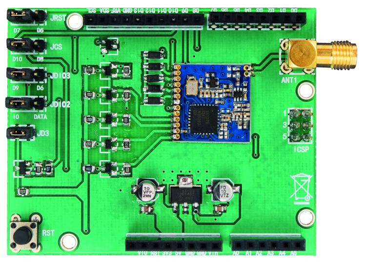
In this last post of the LoRa series we will see how to use the board, so to create a network composed of addressable and safe nodes. Semtech’s SX1278 integrated circuit, on which this shield is based, allows for a sophisticated and efficient communication in the LoRa (Long Range transmission) technology.
This communication is a bidirectional one and has a considerable cover range: about a hundred meters inside the buildings, or about a km in an open field. The board operates in the 433 MHz band and is a low cost one; it is therefore oriented to applications going from the “home automation” to the security, to the monitoring and the agricultural automation.
Since the communication is a bidirectional one, the board is suited to star and mesh network architectures: in the first case there is a privileged node, a reference for the other ones, that may only communicate with it; while in the second one each node may decide to communicate with any other one.
In the previous post we could see how to program the board for a point-to-point communication; in the said application, our attention was devoted exclusively to the verification of the communication conditions and in the reachable range. In fact the application was based on a transmitter that was sending a message and on a receiver that would echo it; no form of communication address was there, and if anyone wanted to use more systems at the same time, the only discriminating factor of the transmissions for the single units could be the carrier frequency.

It is obvious that, in order to create any network structure, an address system for the single communications is needed. But that’s not enough: because of the range, that is not limited to a few meters, the transmission may be easily intercepted and thus it needs a protection system.
Semtech and other subjects of the “LoRa” Alliance” have designed a network protocol named LoRaWAN; it is complex enough and in it, the peripherals having sensors and actuators (“End-device”) are connected to some Gateways that direct the traffic on the Internet network and up to the server that is dedicated to their management. The protocol is a complex one, because of the many variables managed; first among everything is the power supply management of the peripherals, that we tend to reduce to the maximum. Moreover, both the frequency hopping and the data-rate are managed in an adaptive way. The protocol considers even the AES cryptography with a 128-Bit key size, and considers three different “End-device” types: class A, class B and class C. Class A is the basic one and considers the initiative from the peripheral that – after the transmission – opens two small time windows for the reply from the server, and then is turned off. Moreover both the frequency hopping and the data-rate are managed in an adaptive way. The class B has the possibility to have some listening times, while the C may remain as always listening, since it does not obviously suffer from power problems. The LoRaWAN protocol’s specifications may be downloaded from Semtech’s website.
The LoRaWAN protocol is too complex for a more limited structure, such as a small private network for local usage. For this reason we thought to complete the LORA library by implementing an address structure and a protection that uses AES cryptography.

LORA Library: addressing
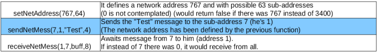
In the protocol we defined, a recipient’s address and one for the sender have been inserted. The address is a 16 bit one (word), that allows for 65,534 possibilities (with the 0 that has not been considered).
In order to make its usage more practical, the address has been divided in a network address and a “device” sub-address; however the subdivision is not a fixed one and may be decided by the user, in the sense that the address’ part that is reserved to the network – and consequently, to the peripherals – is a variable one. In practice, it is a matter of defining the maximum number of addressable peripherals (it must be a power of 2) and a network address being included in the space remaining in the effective address’ “word”. If the network address exceeds the value, the function will return “false”. Obviously, all the nodes will refer to this structure with the same network number and a different node address.
In Table an example of usage of sending and receiving functions is shown.
LORA Library: cryptography
Even if the application that you could have had in mind doesn’t have any real security restriction, it is not appropriate to make the radio packet travel in an unencrypted way, at the distances that may be reached by LoRa transmissions. For this reason we thought about a solution that could be reasonably safe, but also viable on a limited hardware such as Arduino.
Luckily, on the Internet it is possible to download an AES cryptography software, adapted for Arduino. This software, that uses the program’s Flash memory for some basic structures, has been slightly modified by us in the key’s management.
The AES cryptography we used is on a 256-Bit key size, but instead of supplying a 32 bit array, the key is generated in a pseudo-random way, starting from a seed value from Arduino’s random generator. This mode reduces the RAM occupation to a single number (integer), but it has the disadvantage of being usable for Arduino only. In fact, if different math libraries are used, the creation of pseudo-random keys, starting from the same seed, would supply keys that do not correspond among the various boards of the same network.

The AES cryptography with a 256-Bit key size is considered to be a very safe one, in fact the algorithm executes a certain number of transpositions and permutations by means of nonlinear functions, thus creating a completely masked sequence of bytes, that may be compared to the pure noise. Only the usage of the key enables the inverse procedure. Anyway, the library we used adds only a little weight to Arduino, both in terms of processing and memory occupation.
In addition to the AES cryptography, a byte has been added to the message; the said byte has a random value and has the purpose of making the identical messages (that repeat themselves) unique. More importantly, it has been thought in order to allow a possible implementation of an additional security, such as a rolling-code. Please keep in mind that, because of the king of cryptography used, the value of a byte gets scattered on the whole coded message.
The cryptographic key is directly defined in the activation function of the LORA library. The key’s definition is:
![]()
Packet
The packet sent and received in LoRa mode (that is to say, the payload) is therefore composed as shown in figure.

The delivery function builds it by adding the two addresses to the message (upon reconstruction, in word format) and a random value byte. Then the function encodes it (with the exception of the recipient’s address) and sends it. The addressee is not encoded, so to speed up the recognition at the destination. Once a packet has arrived, as a first thing the receiving function checks the recipient: if it corresponds with its address, the function will proceed, otherwise it will discard it. If it falls within the scope of its competences, the function will decode and verify if it was waiting it from the indicated sender (it may also accept messages from whichever sender). In the end, it returns the number of bytes of the message contained in the fitted buffer. It returns 0 if no message is incoming, or if the message is not among those that fall within the scope of its competences. In the case the message is arrived, it is possibile to ask for the sender or for the random marker.
LORA Library’s functions
The basic functions needed in order to use the board in LoRa mode inside a network structure that has been so defined are really a few ones. In Table we propose a summary.

We will now show you a simple example that will highlight its simplicity of usage: it is contained in the library and in this context we will see its main features, and we will leave to you – the reader – the analysis of the complete listing. The example is composed of two sketches and represents a star structure in which a node queries the other ones, but it may also receive some unsolicited warnings in the case in which a certain event occurs on the peripheral. In our simulation the event is the action taken upon a button.

The first sketch represents the central node and has address 1 (anode address inside a network having 15 possible nodes). The sketch initializes the library and the board and then remains waiting for the reply that will be visualized on console. In the case of a spontaneous message, it will be visualized on the console. You will find the corresponding code in Listing 1.
Listing1
#include <LORA.h>
#include <SPI.h>
#define LORANET 333 // network address
#define DEVRANGE 16 // range of node addresses
#define THISADD 1 //address <span class="">of this node</span>
#define KEYVAL 111 // value for the AES key generation
#define RXTIMEOUT 500 // timeout replay
#define inplen 64 // buffer for sending
#define reclen 64 //buffer for receiving
LORA LR; // Class LORA instance
boolean SHIELD=true;
::
void setup()
{
Serial.begin(9600);
if (!LR.begin(KEYVAL))
{Serial.println(“No LoRa shield detected! Stop!”);SHIELD=false;return;}
LR.setNetAddress(LORANET,DEVRANGE);
Serial.print(“Net address : “);Serial.println(LORANET);
Serial.print(“Devices range: “);Serial.println(DEVRANGE);
Serial.print(“My address : “);Serial.println(THISADD);
Serial.println(“LoRa transmitter ready...”);
SX.setPower(PWR);
showConfig();
LR.receiveMessMode(); // set shield in continuous receiving mode
}
void loop()
{
delay(200);
if (!SHIELD) return; //if the card does not work you can do nothing
int nb;
if ((nb=getInput())>0) //If a command has been entered
{if (sendBuff(nb))getReplay();}
if ((nb=getMess())>0) {} //If a spontaneous message prints arrived
}
The commands that may be inserted are connected to an echo request, to a LED’s turning on and off, to making a buzzer sound or to verify the action on a button or a switch. The peripheral node’s sketch (Listing 2), instead, does nothing else but wait for the arrival of a message and verify the action on a button or a switch. In the case a message arrives (command), it executes it and replies. In the case the change of state for a button or a switch occurs, it autonomously sends a warning message.
Listing2
#include <SPI.h>
/* Simulation of sensors and actuators*/
#define psound 9 // pin for buzzer
#define pingo 8 // pin for push-button
#define pinf 7 // pin for signaling led
#define LORANET 333 //network address
#define DEVRANGE 16 //range of node addresses
#define THISADD 2 //address of this node (the other nodes you will have different)
#define KEYVAL 111 // value for the AES key generation
#define MASTER 1 // address of the central node
LORA LR; // Class LORA instance
boolean SHIELD=true;
char recbuff[reclen]; //receiving buffer
char sendbuff[reclen]; //transmitting buffer
::
void setup()
{
pinMode(pingo,INPUT_PULLUP);
digitalWrite(pinf,0);
pinMode(pinf,OUTPUT);
pinMode(psound,OUTPUT);
Serial.begin(9600);
if (!LR.begin(KEYVAL))
{Serial.println(“No LoRa shield detected! It can’t perform echo!”);SHIELD=false;return;}
Serial.println(“LoRa receiver.”);
LR.setNetAddress(LORANET,DEVRANGE);
Serial.print(“Net address : “);Serial.println(LORANET);
Serial.print(“Devices range: “);Serial.println(DEVRANGE);
Serial.print(“My address : “);Serial.println(THISADD);
SX.setPower(PWR);
showConfig();
Serial.println(“Waiting for message...”);
LR.receiveMessMode(); // set shield in continuous receiving mode
}
void loop()
{
int nb;
if (!SHIELD) {delay(200);return;} // if the card does not work you can do nothing
if ((nb=getMess())>0) //If it receives a command executes and responds
{decode(nb);LR.receiveMessMode();} // then he gets back on receipt
if (getInput()) //If the button / switch is pressed sends a alert
{sendWarn();LR.receiveMessMode();} //then he gets back on receipt
}
Conclusions
On GitHub’s website, a page related to this project has been opened: there, in addition to the library, you will find applications that both we – and above all you – will want to share. The applications, as we already said, are almost endless: from the home alarm system to the management of sensors actuators for a small firm.
From openstore
Semtech LoRa SX1278 Transceiver Module

the lora library on github is empty
all the links from here
https://github.com/open-electronics/LoRa/blob/master/Introduction.md
are “dead”
where can I find the lora library for arduino,
that is uses in the example above ?
https://github.com/open-electronics/LoRa/releases
Hi Boris, could you kindly point me to a library for a Lora mesh network for Armbian python at 433 mhz please? My internet connection is via a simcom sim5302E through a raspberry pi 3 . Thanks Boris
Conclusions
On GitHub’s website, a page related to this project has been opened: there, in addition to the library, you will find applications that both we – and above all you – will want to share. The applications, as we already said, are almost endless: from the home alarm system to the management of sensors actuators for a small firm.
Thank you kindly Boris