
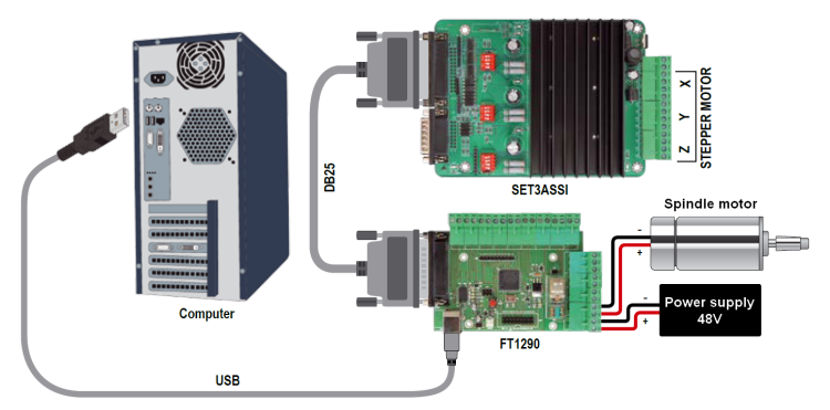
Let’s print the PCBs by means of our CNC machine, that this time has been fitted with a controller that connects to a PC via USB, that draws the control signals and that regenerates timed pulses, simulating the parallel port.
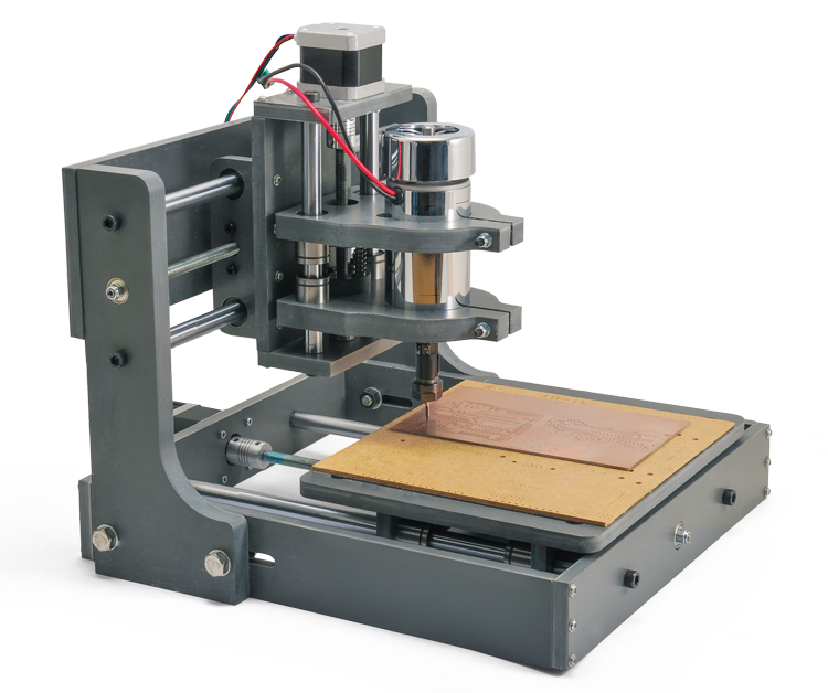
In this post you had the chance to learn about and to evaluate our new CNC milling machine, equipped with a 9,000 rpm electro-spindle and with a compact PVC chassis, and available in assembly kit. This machine, that stands out for the excellent value for money (which is suitable for an amateur CNC machine) has been thought mainly for engraving plaques (such as those for the mailbox, the intercom, the door) and plastic elements (even in POMs, Delrin included). It is then surely possible to work with wood and, without overdoing it, it is possible to engrave (but at a low depth) aluminium plates. In this article we will show you how to use it, for the purpose of engraving printed circuit boards by means of an open source software and a refined hardware solution that enables the management via USB, from the PCs that do not have a parallel port.
As with most CNC machines, even ours is supplied with a 3-axes control board that is interfaced to the parallel board, so that it is possible to drive it by means of software of the Mach 3 kind, that converts the G-code into pulses that are directly produced on the parallel port. Since many desktop PCs and all the notebooks no longer have a parallel port, we thought to a solution that will be described in these pages, and that enables to directly drive it via USB, and therefore by means of all the modern computers. We created this specific board since – in order to manage the CNC machine via USB – it is not sufficient to use a traditional USB/parallel adapter; in fact, as the data would be sent on a virtual LPT and in serial form (since the USB is a serial) and then recomposed in parallel form with a certain delay or, worse, with unequal delays among the bits: this would bring to a situation with movements on the three axes that are not perfectly synchronized, and therefore to mistakes when manufacturing the workpiece.
On the other hand, our proposal is that of a hardware that – by starting from the USB and by taking advantage of the open source software – enables to reconstruct the command pulses for the CNC control board on the machine. It, therefore, enables to keep the original electronics and adds a device that is something more than a simple interface.

The system
In order to understand the usefulness of the interface, it must be said that – in common CNC machines that work on LPT port – the command is usually given by the manufacturing software (e.g.: Mach 3) that starts from the file in the G-code language and extracts the pulses and sends them directly on the lines of the parallel, so to make the corresponding axes advance for a certain number of steps/mm. In practice, Mach 3 executes the G-code and emits specific pulses for the motors, one for each parallel’s pin, and they are synchronized and temporally coherent among them.
If we tried to communicate via USB by means of an adapter, there could be – because of the latency – some synchronization problems among the pulses (since Mach 3 commands the motors via the parallel’s pins and the lines via drivers) and temporal coherence. It is therefore not recommended to use a USB/parallel adapter.
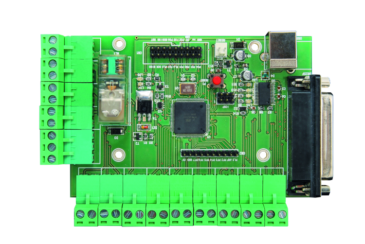
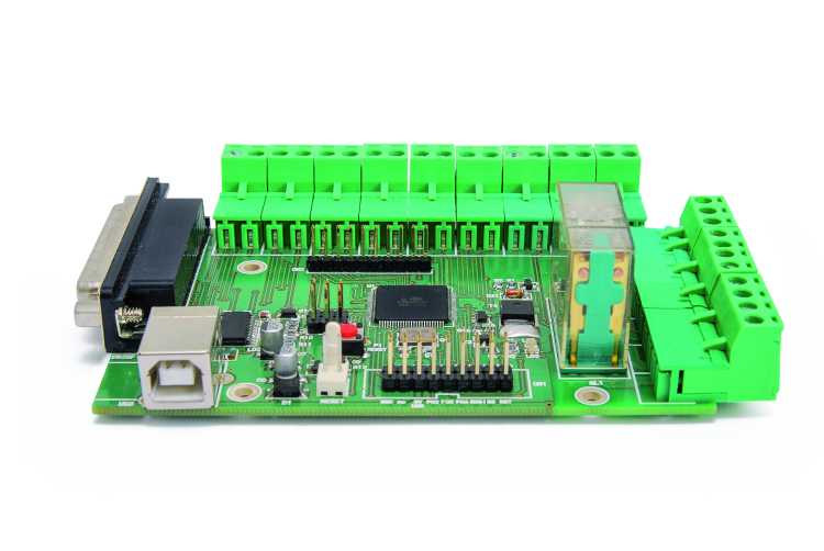
We worked around the problem and created something that is actually a converter subsystem of the commands sent by the CNC control software: a board that connects to the USB on a side while – on the other one – it connects to the 3-axes controller board’s parallel of the CNC machine, via a DB-25 connector. The board converts the received commands, it extracts them from the serial strings arriving on the USB and reconstructs the commands on a parallel connection, by reassigning them the right timings and the temporal coherence, by means of the pulses of all the command lines.
The reconstruction of the command pulses on the parallel – starting from the commands received on the USB – is carried out by an ATmega2560 microcontroller interfacing an USB/TTL converter. We loaded the grbl firmware on the microcontroller: thanks to that, our board receives the G-Code coordinates via USB, and locally generates the pulses on its own parallel, that drives the printer’s original controller. Because of the way the chosen firmware operates, we may not use Mach 3, but only a program that works on USB, such as grblControl, that sends data concerning the coordinates in the format read by our board.
Circuit diagram
Let’s take a look at the board’s circuit diagram, that revolves around the U1 microcontroller, that is to say, the same ATmega 2560 found in the Arduino Mega and Fishino Mega boards; at the start (after the power-on-reset), the microcontroller initializes the PE0 and PE1 lines (respectively as input and output for the data that has been exchanged on the USB, by means of the U3 converter), while PL0, PB6, PB5, PB4, PH4, PH5, PA7, PA6, PA5, PA4, PA3, PA2, PE4, PE5, PK0, PB7, PH3 are assigned to the parallel that has been “reconstructed”, with which to communicate with the CNC controller board. Given that it is a bidirectional parallel, some lines have been initialized as I/Os and other ones as outputs; more precisely, all the lines corresponding to EN, DIR, STEP, RL are outputs (since they send the command pulses to the drivers of the 3-axes board, that is to say, the controller board for our CNC machine), while LIM1, LIM2, LIM3 and LIM4 are outputs, since they are needed in order to read the possible limit switches that it is possible to apply to the machine.
In the following figure helps to understand which ones are the bidirectional I/O lines and which ones are the input lines (printer’s state signals).

On the other hand, the SS, PH0, PH1, PA1, PL3, PL4, PL5, PC0, PC2, PC4, PC6, PF2÷PF7 and AREF lines are actually free and available for possible future developments and evolutions concerning the firmware; we reported them on the CN1 and CN2 connectors for the purpose.
The PK1 line has been assigned to the FEEDH, while the PK2 has been assigned to the CY-ST: both have been initialized by the firmware as inputs, with the pull-up resistor assigned, and they are needed in order to manage the suspension of the cycle. In practice, it is needed to connect to it some normally open buttons that are connected to ground. By pressing the one that is connected to FEEDH the manufacturing is paused, in the sense that only the command series left in the microcontroller’s buffer is executed: after that, the system is paused, the stepper-motors are halted and it waits for a restart command. The bogie and the tool holder head are left in the position in which they were when executing the last command left in the buffer.
In order to restart the cycle, you will have to press the button connected to CY-ST, that works as a “restart” command: the machine’s control software – if fitted for the purpose of recognizing it – will receive and execute it, and so it will restart the data sending on the virtual parallel that is assigned to the USB.

On the other hand, ESTOP is initialized as an input (still with the internal pull-up resistor assigned), and it must be connected to a possible red STOP emergency button. In this case, when it is pressed, the relay output is disabled and the PWM SPIN one as well (for the purpose of stopping the electro-spindle), and our board communicates the stop to the program that is used for managing the CNC machine. The latter requires a manual restart of the manufacturing, that may be restarted from the beginning or from the point in which it was forcibly stopped (in the latter case, please make sure that the restart position is the correct one, otherwise the workpiece will come out poorly).
The ATmega’s PH6 line is initialized by the firmware as an output, with an internal PWM module assigned, and it is used in the case we wanted to directly control the rotation speed of the electro-spindle’s shaft: in fact, it emits pulses that control (they are conveniently buffered by the NOT U2 logic port and amplified in current by the NPN T3 transistor, that is mounted as a common emitter and used as a static switch) the T4 power MOSFET’s gate, at whose drain the PWM SPIN output for the electro-spindle commanding refers to (the electro-spindle should, therefore, be connected between the PWM SPIN output and the power supply’s output positive). In that case, it is needed to join the ground of the electro-spindle’s power supply with the board’s one, as close as possible to the MOSFET’s source, given that the latter operates as a static switch and that it commutes the PWM current pulses on the motor.
The output for the signal of the direction control has been assigned to the PE3 line. It is useful in the case you wanted to drive the electro-spindle’s motor by means of a MOSFET bridge, that enables the inversion of the current flow.
If you prefer the traditional control (the on/off one implemented by the actual 3-axes CNC controller board), the PH3 line drives the NPN T2 transistor, whose collector powers the usual relay with which the 48Vcc power supply’s line on the electro-spindle is commutated.
Please notice that in this project the control of the electro-spindle’s power relay does not occur by means of the output placed on the CNC’s 3-axes controller board, but it is “carried out” onboard, so that it is possible to implement even the proportional control via PWM.
As for the limit switches, we have to start with a small digression: the basic CNC does not have any limit switches, therefore the zeroing of the positions on the three axes (X, Y, Z) must be manually carried out, by ordering the control program to execute a given number of steps, until the position we consider to be the zero is reached. For each production, the machine starts from the current position of the tool holder head and the plate, since it gives the movement coordinates concerning it.
If you’d like to have some references, such as the one for the Home position, you will have to mount (in addition to the existing hardware) some lever microswitches, so that they may detect the said position, for each axis. The said microswitches must be fixed so that their lever is pressed when the corresponding sliding part in the mechanism is in such a position so to correspond to the home position. Please notice that on the grblControl’s user interface (that’s the software we will be using when managing the CNC machine) we have both the Machine coordinates and the Work coordinates: the first ones are those of the machine and they may be obtained via the limit switches or by zeroing the machine, after having manually brought the electro-spindle to the desired position and after having reset – by means of the dedicated buttons – the position. The second ones are on the other hand those corresponding to the ongoing production.
By means of the limit switches it is possible to define the maximum movement on each axis so that the moving parts do not exceed the maximum travel, and so to prevent pointless collisions.
The microcontroller may be locally reset by means of the P1 button, that acts on the /RST line (that is normally kept at high logical level by the R14 pull-up resistor), or remotely: two possibilities are contemplated, that is to say via USB by means of the specific command given from the computer and by means of the Arduino IDE, during the bootloader activation stage (in this case the USB/TTL converter’s DTR is brought to a low logical level and by means of C5 it supplies a negative reset pulse) or by means of the board’s RESET input, to which a clean contact must be applied, so that it closes the electrodes and sends the T1 transistor into saturation, so that the latter’s collector brings /RST to the logical zero. Please notice the Schottky diode, that is used to turn off the negative pulse that would occur at the ends of the R14, when the U3 converter’s DTR returns to a high logical level.
Let’s continue with the analysis of the circuit diagram, and see the U3 USB/TTL converter, that is the typical FTDI FT232RL integrated circuit that converts the signals of the USB line in TTL (0/5V) format, and that deals with the due timings; it is an interface of the Device type and supports the USB 2.0 Full Speed communication. On the D+ and D- input lines there is D4, a dual, bidirectional Zener protection diode, that suppresses possible high voltage pulse noises that may be picked up by the USB cable: that is something we should not rule out if we are using the machine in an environment in which other tool machines are operating.
As for the power source, the board draws from the USB +5V, by virtue of the quite limited absorption of the logic; clearly the USB powers the microcontroller and the LEDs, in addition to a minimum of discrete logic and transistors that are onboard. The USB port’s 5V reaches the power line through the D1 diode, that is used in order to protect the computer’s +5V line, in the case in which the in-circuit serial programming connector (ICSP) is disconnected, without the USB cable being disconnected from the computer. From the diode’s cathode the power – that is well filtered by C4 and C8 – goes through the further filtering of the L1 coil, that cleans it from possible noise pulses (along with C6, C7 and C4, C8, L1 forms a CLC pi filter), and through the microcontroller’s port.
The relay’s coil ( powered by 5V) is powered by the 5V coming from the USB, so to prevent that its commutation disturbs the microcontroller’s functioning.
During the normal functioning, the ATmega2560 microcontroller waits for the arrival of data strings from the USB (on the PE0 pin) and it unpacks them at their arrival, extracts the commands and puts them back together again in parallel form, according to the timings that are required by the 3-axes set board.
The grbl firmware
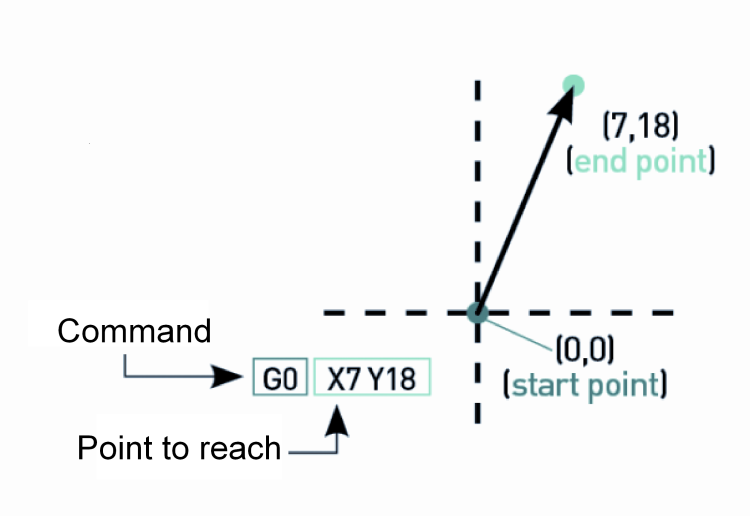
We explained that the installed firmware is grbl; since it is not compatible with Mach3, as for the CNC control software we had to choose one among the compatible solutions that we will describe in these pages, and in the next installment. Grbl is a firmware that was born for the purpose of parsing the G-code and for its conversion in commands on the three axes of a CNC machine. Therefore the G-code sends the coordinates for the movement on the three axes (for example, in order to trace a square we need 4 coordinates and therefore 4 commands: from a point to the second one, from the second one to the third one, from the third one to the fourth one and from the latter to the first one), according to this typical format:
G0 Xn Yn
In which G’ is the command imposing the movement at the highest speed allowed by the CNC (also known as Quick Movement) and X and Y are the coordinates, with n indicating the position to be reached on each of the specified axes . Similarly, a command defines where to bring the axes’ movement (endpoint) and the speed at which to do it: that’s G1, whose syntax is of the following kind:
G1 X7 Y18 F500
in which the F parameter is the movement speed, also known as Feed Rate, that in our machine corresponds to the number of steps per time unit that are carried out by the stepper motor.
In the case of commands imposing a linear movement, our machine converts the coordinates in the commands into steps to be given to the motor (also, keeping the microsteps in mind), so to carry out the movements required by the commands. Grbl has been created for the Arduino world and therefore it may be installed on boards that are based on Atmel’s ATmega microcontrollers, and that have preloaded the bootloader, by means of the same Arduino IDE. In our case, given that it is an open firmware, we customized it by modifying some parts, and especially those that define the structure of the CNC to which the controller board will be paired. The firmware may be downloaded from github.
The conversion of the G-code instructions
into commands that are directed to the motors for the axes’ activation follows certain rules and is carried out by following a certain logic; moreover, grbl supports some functioning modes and standard managements, such as those of the limit switches, of the emergency stop button, of the electro-tool’s adjustment speed, etc.
In Listing 1 you will see an important part of the firmware (the version we are using is the GRBL9FMEGA2560), in which the machine’s operational parameters are defined.
Listing1
#ifdef DEFAULTS_FuturaElettronica
// Description: CNC2018 NEMA 17 stepper motors.
// www.futurashop.it/cnc
#define MICROSTEPS 8
#define STEPS_PER_REV 200.0
#define MM_PER_REV 1.25 // 1,25 mm/rev leadscrew
#define DEFAULT_X_STEPS_PER_MM (STEPS_PER_REV*MICROSTEPS/MM_PER_REV)
#define DEFAULT_Y_STEPS_PER_MM (STEPS_PER_REV*MICROSTEPS/MM_PER_REV)
#define DEFAULT_Z_STEPS_PER_MM (STEPS_PER_REV*MICROSTEPS/MM_PER_REV)
#define DEFAULT_X_MAX_RATE 500.0 // mm/min
#define DEFAULT_Y_MAX_RATE 500.0 // mm/min
#define DEFAULT_Z_MAX_RATE 500.0 // mm/min
#define DEFAULT_X_ACCELERATION (100.0*60*60) // 100*60*60 mm/min^2 = 600 mm/sec^2
#define DEFAULT_Y_ACCELERATION (100.0*60*60) // 100*60*60 mm/min^2 = 600 mm/sec^2
#define DEFAULT_Z_ACCELERATION (100.0*60*60) // 100*60*60 mm/min^2 = 600 mm/sec^2
#define DEFAULT_X_MAX_TRAVEL 185.0 // mm
#define DEFAULT_Y_MAX_TRAVEL 200.0 // mm
#define DEFAULT_Z_MAX_TRAVEL 60.0 // mm
#define DEFAULT_STEP_PULSE_MICROSECONDS 10
#define DEFAULT_STEPPING_INVERT_MASK 0
#define DEFAULT_DIRECTION_INVERT_MASK 224 //((1<<Z_DIRECTION_BIT))
#define DEFAULT_STEPPER_IDLE_LOCK_TIME 25 // msec (0-254, 255 keeps steppers enabled)
#define DEFAULT_JUNCTION_DEVIATION 0.02 // mm
#define DEFAULT_ARC_TOLERANCE 0.002 // mm
#define DEFAULT_DECIMAL_PLACES 3
#define DEFAULT_REPORT_INCHES 0 // false
#define DEFAULT_AUTO_START 1 // true
#define DEFAULT_INVERT_ST_ENABLE 1 // true
#define DEFAULT_INVERT_LIMIT_PINS 0 // false
#define DEFAULT_SOFT_LIMIT_ENABLE 0 // false
#define DEFAULT_HARD_LIMIT_ENABLE 0 // false
#define DEFAULT_HOMING_ENABLE 0 // false
#define DEFAULT_HOMING_DIR_MASK 0 // move positive dir
#define DEFAULT_HOMING_FEED_RATE 25.0 // mm/min
#define DEFAULT_HOMING_SEEK_RATE 250.0 // mm/min
#define DEFAULT_HOMING_DEBOUNCE_DELAY 250 // msec (0-65k)
#define DEFAULT_HOMING_PULLOFF 1.0 // mm
#endif
Among the parameters, we may notice MICROSTEPS, that indicates a possible reduction to the microstep mode (that must be exactly like that in the 3-axes controller board), STEPS PER REV (steps/rev for the motor at the corresponding axis), MM per REV, that is the distance on the axis per each revolution (1.25 is due to the fact that we are using M8 threaded rods, having a 1.25 mm pitch). The settings for the axes follow; in particular, please notice that the STEPS PER MM are the steps required for a 1 mm movement, that are obtained by means of the following calculation: step/rev x microstep/mm x mm/rev. MAX RATE is the linear speed, that depends on the frequency of the pulses driving the stepper motors, and it may be set between 500 and 6000 (we chose 500); that’s the maximum idle speed. The maximum speed when manufacturing on the other hand depends on the resisting force met by the electro-tool.
The section that enables to communicate the axes’ travel and the presence of possible limit switches to the machine is an interesting one: DEFAULT_X_MAX_TRAVEL indicates the travel on the X axis (185 mm), DEFAULT_Y_MAX_TRAVEL indicates the travel on the Y axis (200 mm) and DEFAULT_Z_MAX_TRAVEL (60 mm) indicates the travel on the Z-axis (electrospindle). SOFT_LIMIT_ENABLE concerns the enabling of the firmware limits (at 0 they are disabled) while HARD_LIMIT_ENABLE enables the reading of the limit switches (it must have 1 as a value). HOMING_ENABLE enables (when set to 1) the automatic return to the HOME position.
Therefore, after having downloaded the software in the GRBL9FMEGA2560 version, you will have to edit it by means of the Arduino IDE and set the parameters as in the section shown in the Listing 1 , otherwise the machine will operate in an improper way (for example, the movement might exceed the acceptable one, with the risk to damage the mechanism).
As for the connections, please follow the figure, and remember that the power source of the electro-spindle’s power transformer has to enter through the V_SPIN clamps and exit through SPIN, and to respect the indicated polarity (therefore the external relay of the 3-axes controller board is no longer needed). Af for the usage, you will have to connect the USB / parallel board’s USB socket (by means of a USB A/B cable), and the board’s DB-25 connector to the CNC 3-axes controller (by means of a male/female cable, having two DB-25 at the ends). If the electro-spindle’s power is commutated by the board’s relay, you will have to connect the power rectifier bridge’s positive and negative poles to the corresponding poles of the V_SPIN junction box, and the electrospindle’s wires to the SPIN’s + and -; please notice that, since they are clean contacts, it is actually possible to swap the places of the terminal boxes, that is to say that V_SPIN may be used in order to connect the motor and SPIN may be used in order to receive the 48Vcc power.
As regards the power source, please remember that the board described in this article does not require any power supply in order to operate: in fact, it draws the 5 volts needed from the computer, by means of the USB socket it is connected to. The electro-spindle’s power is simply commutated, but it does not reach the electronic parts.
The adapter board must be inserted in a dedicated plastic container. As for the latter, it is needed to create a window for the USB connector, another one for the DB-25 and another one for the passage of the wires for the electro-spindle and for the possible limit switches that you might have added to the basic CNC machine. It will be possible to fix the emergency stop button (to be connected to the dedicated input contacts) on the container, or close to the CNC (maybe in a box for external electrical systems, a watertight one).
The same goes for the reset button, that you will put on a side of the container, and for the possible pause button (FEEDH) and for the restart one (CY-ST).
Conclusions
Well, we are done, at least as regards the hardware. In the next installment we will show you how to use the interface/CNC whole, for the purpose of crafting printed circuit boards, and without printing anything, without photoengraving, felt pens, films, PCB development, and acid solutions. Here they are literally engraved, by means of a specific tool mounted in the electro-spindle.
As usual, we will start from a gerber file (that is the standard, nowadays, as for the industrial manufacturing of PCBs). The first thing to do is to acquire a CAM, a computer assisted design software, for the creation of elements and mechanical systems. In our case, we will explain how to work by means of FlatCam, that may be downloaded from Internet, at the following webpage: http://flatcam.org/. Once it has been downloaded and installed, please start the FlatCAM program. As for the CNC control software, let’s choose one among the ones that are compatible with our hardware and with the grbl firmware: there are many open source ones; among those offered by the market, we chose grblControl, whose usage will be described in depth in the next installment.
As for now, we will limit ourselves to analyze its main aspects, that is to say the installation and the elements that may be found in the work screen; in the next article, in which we will see how to use if for the printing, everything will be clearer.
The software is free to use and may be downloaded at the https://github.com/Denvi/Candle webpage, in the form of a compressed folder; by unpacking it, the grblControl folder will be obtained: inside of it, we will find the grblcontrol.exe executable file. By clicking on the corresponding icon, it is possible to start the program, whose work screen is the one shown in the figure.
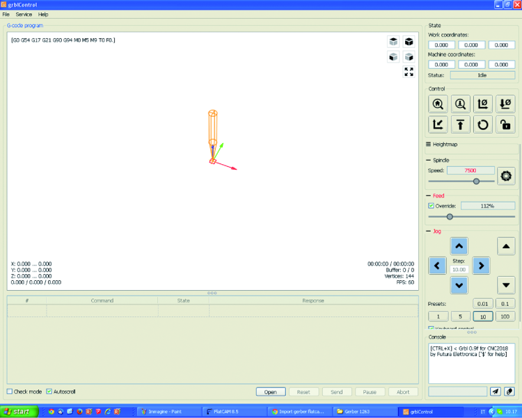
In the central box you will find the workpiece’s design, while in the upper part of the screen there is the menu bar, including the File, Service and Help menus: for example, the first one enables to open and save the file on which you are working on, while the settings are found in the second one.
On the right, you will find the control panel, with the State section found in the upper part, the Control one found in the lower part, and so on. State indicates the CNC machine’s condition (idle or working) while the Work coordinates and Machine coordinates indicate the coordinates at which the three axes are located: in the first case the ones concerning the work being executed are displayed, while the ones concerning the machine are displayed in the second case.
In the Control box, the commands for the manufacturing and the buttons (the two ones on the right) for zeroing the coordinates are gathered. There is also the Spindle box, in which it is possible – if the PWM speed control is activated on the board – to modify the electro-spindle’s revs/min. The console box shows the commands being executed and enables the possibility to give them in G-code.
From openstore
CNC mechanics – kit 200x180x60
Spindle motor 36 Vdc – 300 watt
set board 3 axes + accessories
Switching power supply Mean Well 24 Vdc 150 W
Bipolar stepper motor NEMA 17 – 1,5 A
