- makeITcircular 2024 content launched – Part of Maker Faire Rome 2024Posted 2 weeks ago
- Application For Maker Faire Rome 2024: Deadline June 20thPosted 2 months ago
- Building a 3D Digital Clock with ArduinoPosted 7 months ago
- Creating a controller for Minecraft with realistic body movements using ArduinoPosted 7 months ago
- Snowflake with ArduinoPosted 8 months ago
- Holographic Christmas TreePosted 8 months ago
- Segstick: Build Your Own Self-Balancing Vehicle in Just 2 Days with ArduinoPosted 8 months ago
- ZSWatch: An Open-Source Smartwatch Project Based on the Zephyr Operating SystemPosted 9 months ago
- What is IoT and which devices to usePosted 9 months ago
- Maker Faire Rome Unveils Thrilling “Padel Smash Future” Pavilion for Sports EnthusiastsPosted 10 months ago
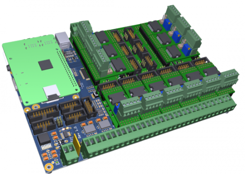
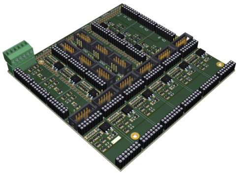
BOAR’S PIGLET 01: our newborn multi-axis development board
Do you like experimenting with many stepper motors and RC servo actuators at the same time, but do you find it hard to manage it easily due to the numerous cable connections that create a sort of jungle on your desk? Fear no more. We have a solution that will make your life a lot easier, your applications more reliable, and your desk a lot less cluttered!
Our Piglet 01 board has unprecedented power capabilities (up to 800W per axis), unavailable until now for the entry-level market. Getting the computational power from the ‘mother‘ board (the Boar’s Board, to which it must be connected), the microcontroller no longer needs to handle or emulate any of these low-level tasks in software. The acceleration and deceleration ramps of the stepper motors, as well as the PWM outputs and PPM outputs, are managed directly in hardware.
Just reunite the Piglet 01 board with its ‘mother’ and enjoy a complete and reliable control system for multi-axis applications, with the added bonus of having a single, comprehensive development board that allows you to concentrate on doing what you want without having to worry about trying to match different boards that were not designed to work together.
Robotics, 3D printing and other applications have never been so easy!
Architecture overview
12 STEPPER sockets supporting both 3A and 10A smart stepper controller (driven directly from the hardware FPGA acceleration core);
12 PWM-capable hi-current outputs (5A) driving resistive loads like 3D-printer heaters, mechanical actuators or other loads;
12 Servo-PPM sockets enabling the user to drive the RC servos directly by using the FPGA-PPM acceleration core;
24 digital inputs with embedded pull-ups, available as generic inputs.
Bonus feature:
both the source codes of the Boar’s Board FPGA and of the microcontroller are available under LGPL licence, allowing further modifications and developments by the user community.
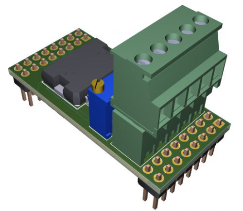
3A STEPPER CONTROLLER BOARD
Smart stepper-controller with embedded zero-detector circuitry
(based on ST L6470)
Voltage Range 8-45 Volt
Current range: up to 3A R.M.S. (7A peak)
Microstepping up to 1/128
Pin-to-pin compatible with the 10A controller
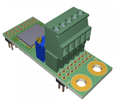
10A STEPPER CONTROLLER BOARD
Smart stepper-controller with embedded zero-detector circuitry
(based on ST powerSTEP01)
Voltage Range 7.5-85 Volt
Current range: up to 10A R.M.S.
Microstepping up to 1/128
Pin-to-pin compatible with the 3A controller


