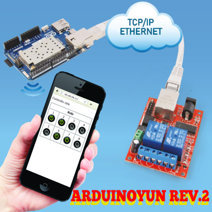
We present an automation solution that provides the ability to control a series of relays, using the local wired Ethernet network. All driven by the new version of the Arduino Yún board.
The project that we present is born from the almost simultaneous availability of two devices that, although of different origins, lend themselves perfectly to being integrated with each other in a removable automation solution. The first device is the Arduino Yún card, now available again, in the new Rev. 2 version, after a period of relative “absence” from the market. The second device is a relay card that can be controlled via TCP / IP on a LAN Ethernet network, with the ETH2RELBOARD code. The project that we propose allows you to use the Arduino Yún board both as a web server and as a time scheduler, to control one or more relay boards located on the local network, according to the reference diagram shown in Fig. 1.

Fig. 1
A small warning. The creation of this application requires a bit of familiarity with the GNU / Linux environment, the writing of programs in HTML, Javascript, PHP and Python. Knowledge of networks and of a router configuration is certainly not bad. As can be seen, the application requires that the Arduino Yún card and the Relay card be connected in a local network via Ethernet connections, obviously also far from each other.
At this point an HTML page, accessible through the Arduino Yún Access Point, allows you to view the status of the relays and output pins. Using the Cron scheduler, available in OpenWRT, it is possible to set the activation of the relays and output pins at preset times, in reality, it is possible to set minutes, hours, calendar days or week and months associated with relay operations.
The choice of Arduino Yún for this application is dictated by the fact that, given the small amount of software required, it is not justified to use a more powerful microcomputer as Raspberry Pi could be.
Arduino Yún
The geometry of the Arduino Yún board has remained almost unchanged, compared to the previous versions. The main “innovations” can be summarized as follows:
- the power supply circuit has been improved and made more robust;
- a USB hub has been implemented;
- the position of the Ethernet and USB connectors is unchanged but they were both arranged so as to reduce the size of the card in height. In particular, the Ethernet connector was lowered inside a recess on the card, as well as the USB connector, which was mounted horizontally, also lowered by means of a recess in the card. These modifications allow the insertion of any expansion shields at a shorter distance from the “main” board without any particular risk of creating short circuits on the connector shields;
- the OpenWRT operating system, which is the engine of the Atheros AR9331 component, has been updated to a version that contains numerous patches for bug fixes and malfunctions.
An important notation concerns the use of the reset buttons on the card. There are three of them, positioned as shown in Fig. 2, with various functions described below:
- 32U4 Reset button – This button allows the reset of the ATmega32U4 microcontroller;
- Yún reset button – Pressing the “Yún reset button” button allows you to reboot the OpenWRT operating system. Clearly, all data in memory will be lost and all active processes will be terminated at the moment;
- WiFi reset button – The “WiFi reset button” has a dual function. Normal pressure allows you to return the WiFi module to the factory configuration, i.e. configured as Access Point with static IP 192.168.240.1 with SSID name “Arduino Yun-XXXXXXXXXXXX”, where the twelve “X” represents the MAC address of the Yún board. To reset the WiFi module you need to hold the button down for at least five seconds… but not many more. The rest of the WiFi module also involves the reboot of OpenWRT. We said not to hold down the button much longer than five seconds because the button has a double function. When pressed for more than 30 seconds it causes the restoration of the OpenWRT operating system with the original version, i.e. the one loaded in the factory. A good option to allow you to recover any clumsy operations. This leaves the freedom to experiment without the fear of being in situations with no way out. Simpler than that. Clearly, the price is to lose all configurations and any updates made on OpenWRT.

Fig. 2
A further reminder of the LEDs on the board, positioned as shown in Fig. 3, and their meaning:
- USB – Blue, indicates activity on the USB connector;
- WLAN (WiFi) – active WiFi;
- POWER – Indicates the presence of power;
- WAN – Indicates the presence of an active Ethernet network connection;
- Pin 13 – Reports the status of pin 13;
- Serial TX – Indicates activity on the serial port being transmitted (for example when using the serial monitor);
- Serial RX – Indicates activity on the serial port being transmitted (for example when using the We still remember that the two Arduino Yún processors can run programs that work together thanks to the Bridge environment, composed of a library for Arduino on the side of the 32u4 processor and the corresponding framework on the OpenWRT site.

Fig. 3
The reference scheme of the functioning of this communication system is shown in Fig. 4. For a more detailed discussion on the functioning of this architecture and on the use of the different functionalities available, we refer you to the reading of the book mentioned at the beginning of the article.

Fig. 4
Relay Card eth2relboard
The board, shown in Fig. 5, is able to drive two relays, physically mounted on the board, and further outputs on the output pins, by means of a TCP / IP interface managed by a microcontroller on the board same.
The “nice” feature of this card is the fact that the TCP / IP interface is not implemented with a web server with an HTML interface, but the card’s TCP / IP application manages a protocol made up of simple commands to be sent via socket TCP or UDP in RAW mode. In this way, it is possible to integrate the use of the card in almost any remote I/O management application. In addition, a series of software applications can be downloaded that allows you to configure and test the operation of the card even in the absence of specific applications. The power supply of the board requires a voltage between 9 and 24V and can be applied using a plug connector or by using the appropriate screw connectors, for a more “stable” use. The relays are able to support a load of 30 VDC at 10A or 250 VAC always at 10A. The status of the relays is indicated with two red LEDs. The green LED indicates the presence of power.

Fig. 5
The important part for our application is the communication protocol to be used to activate and deactivate the relay outputs and to set the Ethernet interface configuration and operating modes.
In the following commands “R” is the number that corresponds to the relay or to the output pin to be operated, “n” is a number expressed in seconds.
0R
Return the status (on / off) of the corresponding relay;
1R
Closes the corresponding relay, if open;
1R*
It closes the corresponding relay, if open, to reopen it after about ½ second;
1R: 0 As “1R”;
1R: No
Close the relay if open; after “n” seconds (1 <= n <= 65535) it reopens it;
2R Opens the relay, if closed.
Note: If the value “X” (1X or 2X) is entered instead of the relay number, the requested operation acts on all the relays simultaneously.
These commands can be sent from a simple terminal window, or from an application running on a microcontroller or microcomputer. Remember: the default configuration requires the relay card to respond to the address:
192.168.1.100
Over ports TCP 6722 and UDP 6723
The card configuration port is:
TCP 5111
Preparation of Arduino Yún
The implementation of this application involves a series of steps that can be summarized as follows:
- update of the OpenWRT distribution with PHP support for the uhttpd web server;
- preparation of the micro SD Card with the software components of our application;
- write programs (or download from the site) and transfer to the SD Card;
- configuration of the local Arduino Yún network to connect to the same subnet as the Relay tab;
- wiring between Arduino Yún and Relay board;
- Cron scheduler configuration;
- test;
- configuration of the Relay tab.
Let’s go in order. First, turn on Arduino Yún. Open the WiFi configuration function of your PC and after a certain period, you will see a new network appear with SSID that corresponds to “Arduino Yun-XXXXXXXXXXXX” where the sequence of “X” represents the unique identifier of your Arduino Yún. By default, Arduino Yún has a subnet with IP address 192.168.240.1/24. Choose to connect to Arduino Yún’s SSID, for which there is no password. You will be automatically assigned an IP address by the OpenWRT DHCP server.
At this point you can connect to the OpenWRT terminal window, for example, using the now ultra-pure Putty application.
Connect using the SSH protocol and setting the address 192.168.240.1. At the request of a user, answer with: root and password: Arduino. You will be presented with the screen shown in Fig. 6.

Fig. 6
Now connect a cable from your local network to the Arduino Yún Ethernet port. Be careful: if you try to insert the network cable you risk pressing the Reset button on the WLAN. Enter the command:
ifconfig
and verify that the eth1 network interface has an address that belongs to your local network. This is essential because, to update the OpenWRT distribution, it must be possible
connect to the public Internet.
If everything is correct, type the command:
opkg update
This command allows you to update the repository of packages available for updating OpenWRT. At the end install the components for the execution of PHP programs in CGI mode. Enter the command:
opkg install php7 php7-cgi php7-cli
as shown in Fig. 7. At the time of writing this article the current PHP version is the “7”.
In case of problems, check the version of PHP available with the command:
opkg list php*

Fig. 7
To have the PHP programs managed by the OpenWRT web server, that is uhttpd, you need to update the uhttpd configuration file.
Using WinSCP, always pointing to the address 192.168.240.1 with user “root” and next password “Arduino”. Go to the folder:
/etc/config/
and open the file:
uhttpd
Edit it, adding the directive:
list interpreter “.php=/usr/bin/php-cgi”
as shown in Fig. 8. Save and close. Now restart the uhttpd server with the command:
/etc/init.d/uhttpd restart

Fig. 8
Now it’s time to prepare the micro SD Card where we will put our programs. An 8GB micro SD card will do just fine. Insert it into your PC’s slot and create folders:
/arduino/www
/data
Remove it from your PC and insert it into the Arduino Yún slot. Always with WinSCP go to the folder:
/www/sd
and create a file with the name phpinfo.php
insert the following text, as shown in Fig. 9:
<?php
phpinfo();
?>

Fig. 9
Open a browser and type in the address:
192.168.240.1/sd/phpinfo.php
If you get the result visible in Fig. 10 everything works properly.
At this point, it is necessary to make the connection between Arduino Yún and the Relay card.
First, you need to configure the Arduino Yún WAN interface in order to let it participate in the same subnet as the Relay tab. From the browser enter the address:
192.168.240.1

Fig. 10
After a short time, the login page of the OpenWRT configuration application will open, as shown in Fig. 11. Enter the “Arduino” password. On the next page click on “CONFIGURE” and then on “advanced configuration panel (lights)”. From the top menu select “Network >> Interfaces” (Fig. 12).

Fig. 11
On the new page, click on “WAN” on the top left, and configure the new page as shown in Fig. 13.
Fig. 12
In the order:
- select “Static address”;
- click on the “Switch protocol” button;
- enter the address “192.168.1.1”;
- enter the Netmask “255.255.255.0”;
- Click on the “Save & Apply” button at the bottom of the page.

Fig. 13
Wait until everything ends. Connect the Arduino Yún Ethernet interface with the Ethernet interface of the Relay card. Power up the Relay tab and return to the connection with WinSCP to the Arduino Yún file system. You will have to create a structure identical to the one shown in Fig. 14.

Fig. 14
Create an empty file named “sr201.py”. Retrieve the contents of the file from the GitHub repository at the address:
https://github.com/berkinet/sr-201-relay
Copy the program into your file and save.
Now download the other files and copy them to the same folder / www / sd /.
In the browser type the address:
192.168.1.100/sd
and you will get the page visible in Fig. 15.
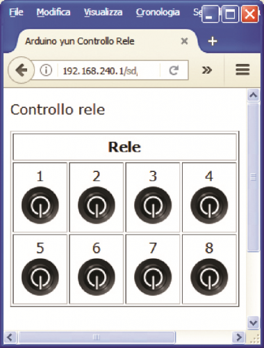
Fig. 15
The web application is a classic HTML page, which uses the AJAX architecture to send commands to the web server and to keep the status of the relays and output pins updated. Fig. 16 shows some Relays in the “on” state and others in the “off” state.
With this small application, you can activate and deactivate your relays and pins remotely. The AJ_stato.php program is cyclically launched by the browser to keep the status of the relays and pins updated and is activated whenever you click on one of the “switches” that activate or deactivate the relays or output pins. These last programs use the features provided by the “sr201.py” program that you downloaded from the GitHub repository.

Fig. 16
This program can also be used from the command line. Type from the terminal window:
python /www/sd/sr201.py 192.168.1.100 close:1
or
python /www/sd/sr201.py 192.168.1.100 open:1
Where the number after the “:” is the number of the relay or output pin. By replacing the number you can activate or deactivate any output.
To get the status of the Relay card type:
python /www/sd/sr201.py 192.168.1.100 status
If you want to enable or disable the Relay board outputs according to a pre-set calendar, go back to the OpenWRT configuration application. From the menu select “System >> Scheduled Tasks”. A configuration window will open which is nothing other than the Cron scheduler configuration file. Enter the following declarations (Fig.17):
1-59/2 * * * * /usr/bin/python /www/sd/sr201.py 192.168.1.100 close:3
0-58/2 * * * * /usr/bin/python /www/sd/sr201.py 192.168.1.100 open:3
These instructions will activate output 3 every odd minute of every hour and will have it deactivated every minute of every hour.

Fig. 17
We have described Cron in many articles and in particular in the book mentioned at the beginning.
We report only a summary of the valid combinations.
Each time parameter can be configured as a series of values (for example 0.3.7.9); as an interval (for example 3-7); a mixture of the two (for example 0.3, 4-6.9); or again as a frequency * / 5 (every 5 minutes, hours, etc.).
Click on the “Submit” button.
Then, from the terminal window, type:
service cron restart
to make the declarations operational, otherwise, you will have to switch Arduino Yún off and on again.
If you keep the browser page open, at the end of each minute you will see the image of the switch corresponding to output 3 change, depending on whether it is in the “on” or “off” status.
Relay card configuration
If you want to integrate this application into your local network, you must properly configure both the router component of the OpenWRT system and the Ethernet interface of the Relay card. To perform this task it is good to have some knowledge of the configuration of TCP / IP networks, especially with regard to security. As you may have noticed, the accesses are without a password, apart from the OpenWRT configurator, and this is certainly not the best in terms of security. If you decide to integrate the application into your network, protect it properly. Returning to the configuration of the Relay tab, we recommend using the tool provided by the manufacturer. You can find it in the files in the ETH2RELBOARD card documentation. In order to use this tool, it is necessary to connect, with a direct cable, the Ethernet interface of the Relay card with the Ethernet interface of your PC. Then assign a static IP address to the PC network interface that belongs to the same subnet as the Relay tab, for example, 192.168.1.30. Download the file, unzip it and run the “Config Utility.exe” program. The application is shown in Fig. 18 opens.

Fig. 18
Click on the “Connect” button and, in the pop-up window, enter the address of the Relay tab, typically 192.168.1.100. Click on “OK” and you will get the configuration window shown in Fig. 19. Set your configurations and then confirm by clicking on the “Save” button.

Fig. 19
From openstore
Compact switching power supply 5 Vdc / 2 A plug DC output
Compact switching power supply 12 Vdc / 1,2 A plug DC output

hello, can I get a copy of the files mentionned in fig 14 please.
thank you
Vincent