Let’s go deeper into enhancing techniques for ADC reading and let’s take a look at the first practical examples of analog data reading coming from sensors. Part two.
In the first part of this tutorial we have introduced the functioning of Arduino AD converter, which is associated to the input pins A0÷A5 (ANALOG IN). Now, let’s go deeper into the enhancement technique for ADC reading and how to use both fixed and variable resistor voltage divider and let’s see the first practical examples of analog data reading coming from sensors.
Enhancing techniques for ADC reading
We are going to start this part two by saying that the simple rating of an analog piece of data, without taking advantage of a series of hardware and software precautions, tends to show rather unstable data; these, from a hardware perspective, depends on the missed uncoupling between power voltage of the ADC (AVCC) and general power (VCC), besides the absence of a filter on the reference voltage (ARef).
Unfortunately Arduino, at least in the models we have tested so far, does not have any of these elements, and the only applicable one is the ARef filter. However, it is useful to understand how it works in order to use it on standalone circuits without any problem.
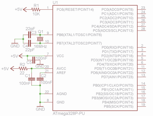
The uncoupling between AVCC and VCC can be obtained using a 22 ohm resistor connected in series to the positive power terminal and a 100 nF capacitor on GMD, which together form a low pass filter, cutting a good portion of high-frequency ripple which is normally present on the voltage and increasing both stability and precision of the reading. We can have better results by swapping the 22 ohms resistor with a 10 µH impedance (inductance).
The ARef filter can be made using a 100 nF capacitor between ARef pin and GND.
In the figure we have reported the classic diagram for an ATmega328P in standalone mode with the two adjustments described above; of course, those adjustments are useful only if the circuit will be used for acquiring analog data, guaranteeing an accuracy of ±1 count, otherwise, they will be meaningless.
Later in this article we will show some configuration for the ADC; note to help you doing some quick experiments on them, we have prepared a series of small sketches complete with the images from this article.
In the initial notes of each sketch, we have reported the corresponding figure number (although there can be more than just one) and a brief description of the hardware configuration.
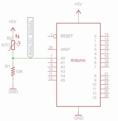
Some analog sensors tend to cause unstable values when there is no signal to measure (once, when not active, still guarantee a stable logic level); in this case is better to include a pulldown resistance or a pull-up resistance, that is a resistor (typically a 10 kΩ resistor) connected, respectively, between the analog pain and GMD or between the analog pin and VCC (normally 5 V).
The pull-down resistors are used when we need to read positive voltages, e.g. those coming from sensors providing a signal that is directly proportional to the event to measure; on the other hand, the pull-up resistance is used when we have to read negative voltages, i.e. when we have to acquire a signal coming from sensors providing a signal that is inversely proportional to the event to measure.
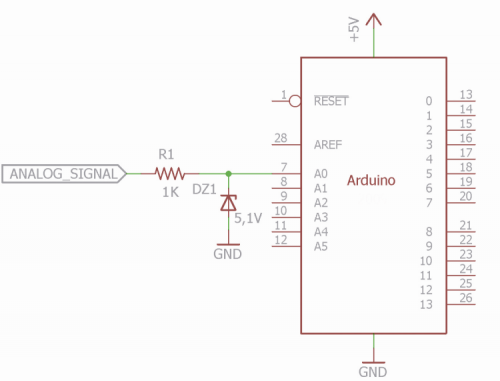
Finally, although in this case we are talking more about protection than stability and accuracy, when working with sensors powered by voltages higher than VCC (regardless of ARef value), in order to prevent possible malfunctioning, it’s good practice to use a Zener diode, with a slightly higher value than reference voltage, with its cathode on Arduino’s pin and the anode on GND, connected in series to a resistor in order to limit the current . This way, in case the voltage to measure is erroneously higher than the Zener’s, it will start conducting towards GND, therefore cutting off the excess value.
Of course, when we interface a sensor which is powered with a voltage higher than VCC, the signal is properly processed (usually through a voltage divider), so that, when the output voltage from the sensor peaks, there is a voltage on the analog pin close to the ranch of admissible values; therefore, the Zener is used as protection only in case of malfunctioning.
The Zener diode must, of course, have a limiting resistor which is almost always the diode’s internal resistance; however, in some cases, we have to add one externally: this is the case where, besides the Zener, there is a current-limiting resistance. Of course, this component must be included only if there is actually the need to protect the micro’s input.
Please note how in figure and in the following illustrations we have in reported the entire circuit needed for a good functioning of the ADC; we are just assuming it wherever it can be used, although in this case the diagram is based on Arduino and not on the ATmega328P-PU, therefore we are very limited in terms of these interventions.
In order to improve the rating of analog values, we can also act on the softer side; basically, we can make use of the two modes described below.
- Take the average of a certain number of reading made in a short period of time and then provide a unique result; in this case, by taking for instance 10 consecutive values: 512, 513, 512, 522, 514, 512, 518, 510, 508, 512, the resulting average would be 513, so before maximum and minimum peaks but the (522, 518 e 508, 510) and they would be basically ignored. Of course this technique is valid only in those cases when we are measuring generally stable values or values which vary very slowly over time, otherwise, we would have the opposite effect. For instance, if we are measuring room temperature, it is very unlikely to experience fluctuations of 1 or 2°C over a few milliseconds, therefore this techniques might be good; however if we think about sensor for measuring distance or movement it is apparent that, since we need real-time measuring, the average of a multiple measurements would provide highly unreliable data.
- Another method to increase accuracy is to increase the ADC’s conversion bits via software and therefore resolution, a technique called “oversampling”.
Oversampling makes use of quantization error between measurements, i.e. those millivolts representing difference in excess or defect between the actual value of the voltage and the minimum step of the DAC, and the noise overlapped to the signal; as a result, and as counterintuitive as it sounds, a perfectly clean voltage (that is a noise-free signal) doesn’t allowed to correctly use oversampling.
The technique calls for acquiring 4n samples, where n is the number of bits to acquire, which must then added up and divided by 2n. For instance, the ADC of the ATmega328P is a 10-bit one, so it returns a maximum value of
210 – 1 = 1.023; but since we don’t want to pass from a 10-bit resolution to a 11-bit resolution, we acquire four readings (41=4) and add the corresponding values together, then we divide the result by 2 (21=2).
Now, let’s suppose we are going to read the four values 1000, 1002, 1002, 1000, which sum is 4004, which divided by 2 provides a final reading of 2.002; this last value is within the new 11-bit range.
(211 – 1 = 2047) and the new resolution (provided the standard 5 V reference) is now 5V/2048=0.002441 V, that is 2.44 mV.
If we want to switch to 12 bit we acquire 16 readings (42=16) and divide them by 4 (22 = 4), in this case, the new range is 212 – 1 = 4.095 and the new resolution is 5V/4.096=0.001220 V, that is 1.22 mV.
Of course, this increase in accuracy has its cost, which is a bandwidth reduction; by switching from 10 to 11 bits, bandwidths is reduced to 1/4, switching from 10 to 12 bit bandwidth reduces to 1/16, and so on, therefore it is highly advisable to increase over 2 bit.
Usually, the oversampling technique is used when reading speed is not a priority while we need to have the maximum possible resolution.
Analog Sensors
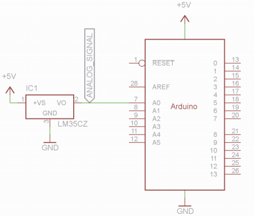
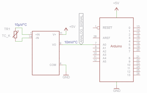
This term describes all those active or passive components that turn a physical quantity in an electric quantity (voltage or current) that can be easily measured. An active sensor, generally speaking, is a powered sensor which, reacting to variations pf the physical quantity to be measured (i.e. temperature), provides a proportional voltage to the measured value on its output pin; one example is the LM35 Ic which, being powered by its three pins, provides a voltage which increases when environmental temperature increases, so directly proportional to the temperature with a drift coefficient of 10 mV/°C. This kind of sensors can be directly connected to an analog pin of Arduino, in fact in order to read positive temperatures, it can be powered using the same power voltage of Arduino.
Please note that we don’t need to connect a pull-down resistor since, as explained before, active sensors constantly provide a 0+V value, so they stabilize voltage themselves; the pull-down resistor is generally necessary to keep a line on 0 V when what’s connected to that line can’t (or nothing is connected), just like pull-down resistors can be used to keep logic level high when there is nothing else that can do it.
On the other hand, a passive sensor is a component which characteristics are influenced by a physical quantity to be measured, so there is no need for external power. An example is an NTC (Negative Temperature Coefficient) thermistor which resistance value decreases with the temperature (and vice versa). Resistance variations caused by these sensors, however, cannot be directly interpreted by Arduino’s analog pins, so they need to be converted.
The Resistive Divider
In case of resistive sensors, this must be inserted in a circuit, the so-called “variable resistive voltage divider” which, with an external power, can generate a voltage which is mostly proportional to the variation of the resistive value of the sensor; in short, by inserting a passive sensor in a fitting powered circuit, we turn it into an active sensor which can be directly read by the analog pin of Arduino. There are other passive sensors capable of directly generating voltage values, given their specific physical properties, but this voltage has such small values that it is unreadable by the analog pin. That’s the case with thermocouples (there are many different kinds, the main one being K, J and T) which are components made of two metallic elements of different nature (with different atomic structure), joined at one end and separated at the other end, where it is indeed possible to measure voltage differences of around 10 µV per degree Celsius; this voltage comes from the Seebeck effect, i.e. the difference of electric charge in the contact section between two metals with different valance. In this case, we don’t need a converter but a voltage amplifier, capable of bringing the signal to at least 5÷10 millivolt (mV) per °C which in this case can be directly measured by Arduino’s ADC.
All right, a few moments ago we have defined the favorable resistive voltage divider as a circuit capable of transforming a passive sensor, a resistive sensor, in an active one; this case, the sensor is a parable element of the voltage divider and it is used together with another fixed value element, acting as a reference.
But there are situations in which the resistive divider is made of two fixed elements, in order to reduce the volt amplitude of the signal having a voltage that is higher compared to the power voltage of Arduino.
Until now, we have “used” Arduino in ideal conditions, that is by applying to analog inputs only voltages lower than the reference voltage and there are many situations where this ideal condition is absolutely possible: for instance, with sensor operating at 5 V; but, what happens when we are forced to work with analog voltages that are way higher, for instance with the standard 12 V or even 24 V of many sensors? Things are definitely different here, at least for what concerns protections of the input/outputs of the microcontroller; if we don’t take the right precautions, where going to inevitably destroy it at the first wrong reading!
So, it’s time to use the fix resistive voltage divider, composed of two resistances which value will be calculated based on formulas we are going to see in the third and last part and which keys we have reported in the previous page. The goal is to obtain a “proportional” reduction of maximum analog voltage, in order to bring it to a value that we are going to call VRidotta, equal or lower than ADC’s reference voltage.
Conclusions
In the third part, we are going to propose formulas and calculations in order to quickly obtain the values of the resistance to be used based on known parameters, and we are going to extract the inverse formulas that might be useful in different situations.
From openstore

3appointed