Let’s get practical with some examples of combinations of sensors working at different voltages and references for the A/D converter of Arduino. Third and final part.
After getting to know and having studied in details the ADC contained in the ATmega328P microcontroller which is equipped with Arduino Uno board’s and more, and after having familiarized with the optimization of acquisition techniques, let’s finish this tutorial by presenting a series of examples based on possible combinations between sensors working at different voltages and the ADC reference (ARef) that must be adopted with each specific practical case. Then, we’ll see what to do with a series of “classical” cases, starting from some connection examples with Arduino and some active general purpose sensors, in different combinations.
In order to comprehend the formulas, we will have to refer to the key table for bridging formulas (you can find it in the next pages), containing the legend for all the abbreviations we have used in the calculation examples and that you will you will encounter in the corresponding formula.
Let’s start with the first practical example.
12 V sensor, DEFAULT 5V reference
We introduce this first example by saying that applying an analog pin with a voltage value higher than reference means there is the concrete possibility to “burn” the micro; for this reason, that signals amplitude must absolutely be reduced. This is the canonical practical case in which we have to make use of the fixed resistive voltage divider.
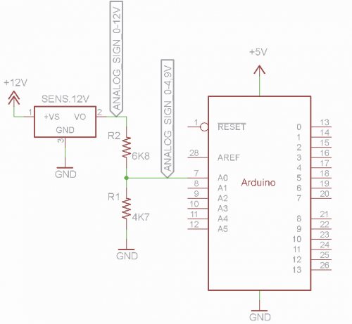
To be specific, we know both the analog signal voltage (12 V) and a reference voltage to provide to the A/D converter (5 V); then, we have to obtain a VRidotta no higher than 5 V when the sensor provides 12 V on the output.
To this purpose, all we have to do is establish a value we want to use as a pull-down, e.g. 4.7 kΩ (4.700 Ω) since it is a widespread value.
With these three values, we can extract the overall value of the voltage divider and therefore of the R to connect in series to the analogic signal. The formula to use is:
RSensore = (VMaxSensore * RPulldown / VRiferimento) – RPulldown
From which we get:
RSensore = (12 V * 4700 Ω / 5 V) – 4700 Ω = 6580 Ω
Note that in the formulas, resistances are defined by their values in ohms; also remember that 1 kΩ is equal to 1.000 Ω.
The resistance to connect in series to the sensor must be 6.580 Ω; the nearest commercial value is 6.800 Ω, but of course, we then have to recalculate the conversion value, using another formula:
VRidotta = VMaxSensore / RPartitore * RPulldown
Where RPartitore is equal to:
R1 + R2 = 6.800 Ω + 4.700 Ω = 11.500 Ω.
By applying that formula, we can see how VRidotta doesn’t correspond to VRiferimento; in fact, we have:
VRidotta = 12 V /11.500 Ω x 4700 Ω = 4,90 V
Instead of the expected 5 V.
if you don’t want to give up having a well-defined value outside of commercially available ones, you can make use of a trimmer instead of the fixed RSensore, possibly of the multi-turn variety, that will be used as rheostat, i.e. a variable resistance, in order to obtain the desired value; the value of the trimmer should be at least 50% higher than the calculated RSensore, in our case we can do with 10 kΩ (10.000 Ω).
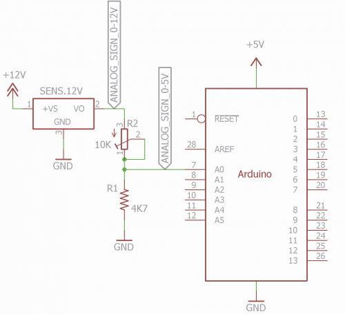
Basically, by applying an exact 12 V voltage to the dividers terminals, we will have to turn the trimmer’s screw until we read exactly 5 V on the contact point between trimmer and pulldown resistor. This method guarantees an excellent precision, but it has the disadvantage to require calibration. Back to the fixed value resistance, in most of the cases, a couple of a fixed value resistors will suffice, however, it is good practice to always use metallic layer resistors in order to guarantee currency instability, going from 0 to 5% to 1% tolerance, compared to 5% of, resistors. Later on, we will make some calculations with nominal values of resistances; actually, you should measure the precise ones in the formulas; in fact, you have to take into consideration that each difference will influence the final value obtained, so at software level (when you are going to convert the analog values read in the measure to be displayed) you could obtain ratings that are substantially different from real ones.
Important note: it is very unlikely to get a commercially available value for RSensore on your first try, so of course you have to settle for the closest value available; this case is, you should always use the closest higher resistance value.
In fact, while a higher resistance value causes VRidotta to be slightly lower than VRiferimento, a lower value could bring VRidotta to a higher value than ARef, so the higher measurement values of the sensor would be over the range, so this condition must be avoided.
In this situation, we’re not talking about risks, in fact, a few hundred millivolts of extra voltage can be easily tolerated by Arduino’s pins.
Back to the example at hand, basically when the sensor provides exactly 12 V output, you will get 4.9 V on Arduino’s analog pin, which is a definitely acceptable value my, from that, you can then calculate:
FattoreRiduzione = VMaxSensore / VRidotta
that is:
FattoreRiduzione = 12 V / 4,9 V = 2,45.
We will have to keep this value in mind, in fact, on the software side, we, of course, will have to reconvert from decimal to Volt.
Now, let’s calculate reading resolution:
Risoluzione = VRiferimento / 1024
else:
Risoluzione = 5 V / 1024 = 0,0049 V (4,9 mV)
On a software level, in order to get back to the original voltage of the sensor we will make this simple calculation:
VOutSensore = LetturaDecimale x Risoluzione x FattoreRiduzione
Basically, if we are going to read a value of 600, this will correspond to:
VOutSensore = 600 x 0.0049 V x 2,45 = 7,20 V
So, as you can see, you don’t have to stress too much over the non-perfect correlation between 12 V on the sensor and 5 V of the ADC reference, but you just have to correctly calculate the reduction and resolution factor. Of course, still on the software side, if the divider doesn’t perfectly reduce the 12 V to 5 V, therefore if the dividers expected ratio is not respected, the end scale will change; in fact, if we repeat the previous formula using the maximum value of 1023, that is:
VFondoScala = 1023 x Risoluzione x Fattore riduzione
In our case:
VFondoScala = 1023 x 0.0049 V x 2,45 = 12,28 V
From this, we get an alternative formula to calculate VOutSensore:
VOutSensore = LetturaDecimale x VFondoScala / 1.023
In fact, in the previous example:
VOutSensore = 600 x 12.28 / 1.023 = 7,20 V
In order to check if everything has been calculated correctly, we try to change the pulldown resistor and go over the formulas once more (this time, without explanations).
We use a pulldown value of 10 kΩ.
RSensore = (VMaxSensore * RPulldown / VRiferimento) – RPulldown
RSensore = (12 V * 10.000 Ω / 5 V) – 10.000 Ω = 14.000 Ω
the closest commercial value is 15 kΩ;
RPartitore = RSensore + RPulldown
Therefore:
RPartitore = 15.000 Ω + 10.000 Ω = 25.000 Ω
By applying the formula:
VRidotta = VMaxSensore / RPartitore x RPulldown
We get:
VRidotta = 12 V / 25000 Ω x 10000 Ω = 4,8 V
Which is still an acceptable value; from there, we can then calculate:
FattoreRiduzione = VMaxSensore / VRidotta
That is:
FattoreRiduzione = 12 V / 4.8 V = 2,5
Now we calculate the reading resolution:
Risoluzione = VRiferimento / 1024
Therefore:
Risoluzione = 5 V / 1024 = 0.0049 V (4.9 mV)
As we have already explained, the following formula allows to go back to the sensor’s original voltage:
VOutSensore = LetturaDecimale x Risoluzione x FattoreRiduzione
Basically, if we read a value of 600, which will correspond to:
VOutSensore = 600 x 0.0049 V x 2,5 = 7,35 V
In this case, a reading of “600” corresponds to a different voltage value, compared to the previous case, due to the different reduction factor.
Finally, we have:
VFondoScala = 1023 x Risoluzione x Fattore riduzione
From which we can obtain:
VFondoScala = 1023 x 0.0049 V x 2,5 = 12,53 V
and therefore, the alternative formula to calculate
VOutSensore:
VOutSensore = LetturaDecimale x VFondoScala / 1023
Which corresponds to:
VOutSensore = 600 x 12.53 / 1023 = 7,35 V
Now, let’s move on to the second practical example.
5V sensor, EXTERNAL 3,3V reference
This is a peculiar case, in fact, we decided to use 3.3 V scale despite having a 5 V sensor. We have already explained that the EXTERNAL parameter is used when you want to obtain a particular scale or in order to provide a stable reference to the ADC, through a precise reference voltage. In this example, we are going to use an integrated accuracy regulator to provide 3.3 V as reference for the ADC; this 3.3 V also be the end scale of the ADC, that is the voltage for which the microcontroller will measure the value 1023.
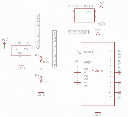
Here, we know both voltages of the analog signal and the reference voltage for the ADC; we decide to use a 10 kΩ (10.000 Ω) pulldown resistor. Let’s move on with the calculations:
RSensore = (VMaxSensore x RPulldown/VRiferimento) – RPulldown
Therefore:
RSensore = (5 V x 10.000 Ω / 3.3 V) – 10.000 Ω = 5.151 Ω
The close is commercially available value is 5.6 kΩ, the divider’s overall value is:
RPartitore = RSensore + RPulldown
Therefore RPartitore = 5.600 Ω + 10.000 Ω = 15.600 Ω
hence:
VRidotta = VMaxSensore / RPartitore x RPulldown
From which we get:
VRidotta = 5 V / 15.600 Ω x 10.000 Ω = 3.21 V
So we can calculate:
FattoreRiduzione = VMaxSensore / VRidotta
that is:
FattoreRiduzione = 5 V / 3.21 V = 1,56
All of this means that when the sensor provides a 5 V output voltage, the analog pin of the microcontroller will actually get to 3.21 V.
now let’s calculate reading resolution:
Risoluzione = VRiferimento / 1024
Therefore:
Risoluzione = 3.3 / 1024 = 0.0032 V tat is 3.20 mV
On a software level, in order to get back to the original voltage of the sensor, will have to make some simple calculations; so for instance, if we read a value of 600, it will correspond to an actual input voltage of the ADC equal to:
VAnalogica = LetturaDecimale x Risoluzione
Therefore: 600 x 0.0032 V = 1.92 V, in order to get the effective value outputted by the sensor (therefore before the divider), we will apply this formula:
VOutSensore = LetturaDecimale x Risoluzione x FattoreRiduzione
VOutSensore = 600 x 0.0032 V x 1,56 = 3 V
Got a hand, a simple ratio from confirms what we just obtained:
VMaxSensore : VRidotta = x : VRealeADC
= That is: 5 : 3,2 = x : 1,92 where x = 3 V
Finally, we have:
VFondoScala = 1023 x Risoluzione x Fattore riduzione
That is:
VFondoScala = 1023 x 0.0032 V x 1,56 = 5,11 V
Now we get to the alternative formula to calculate VOutSensore:
VOutSensore = LetturaDecimale * VFondoScala / 1023
Which is equal to:
VOutSensore = 600 x 5.11 / 1.023 = 3 V
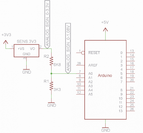
3.3 V Sensor, INTERNAL 1.1 V reference
In this case, we have a similar situation to the previous ones, because all we have to do is decrease the amplitude of the signal. The sensor works at 3.3 V and we decide to activate the internal reference of Arduino’s ADC, or better, of its ATmega328P. This time we decide to use a 3.3 kΩ pull-down resistor.
Let’s move on with the calculations:
RSensore = (VMaxSensore * RPulldown / VRiferimento) – RPulldown
Therefore:
RSensore = (3,3 V x 3.300 Ω / 1,1 V) – 3.300 Ω = 6.600 Ω
The closest commercial value to 6.600 ohm is 6.8 kΩ, at least the first value immediately higher. The overall resistance value of the divider is:
RPartitore = RSensore + RPulldown
Therefore:
RPartitore = 6.800 Ω + 3.300 Ω = 10.100 Ω
Hence:
VRidotta = VMaxSensore / RPartitore * RPulldown
from which we get the value:
VRidotta = 3.3 V / 10.100Ω x 3.300Ω = 1.08V
From which we can calculate:
FattoreRiduzione = VMaxSensore / VRidotta
That is:
FattoreRiduzione = 3.3 V / 1,08 V = 3,055
Now, let’s calculate the ADC’s reading resolution:
Risoluzione = VRiferimento / 1024
Therefore:
Risoluzione = 1.1 V / 1.023 = 0.0011 V cioè 1,1 mV
On a software level, in order to go back to the original voltage of the sensor we have to make this calculation:
VOutSensore = LetturaDecimale x Risoluzione x FattoreRiduzione
Practically, when read a value of 600, it will correspond to:
VOutSensore = 600 x 0.0011 V x 3.06 = 2.02 V
Finally, we have:
VFondoScala = 1.023 x Risoluzione x Fattore riduzione
That is:
VFondoScala = 1023 x 0.0011 V x 3.06 = 3.44 V
And therefore the alternative formula to calculate VOutSensore:
VOutSensore = LetturaDecimale x VFondoScala / 1023
Which is equal to:
VOutSensore = 600 * 3.44 / 1023 = 2.02 V
Passive sensor, 5 V DEFAULT reference
In this case, also, we have a different issue than the previous cases; now the sensor is a passive one and we have to insert it in a divider in order to make it active. In this case, the sensor will be part of the sensor’s resistance, therefore the only value to calculate will be the pulldown value. The application diagram is shown in the figure of the previous part of the serious.
For our example, we consider a NTC thermistor (already previously described). Each type of NTC has some specifics which basically are the ohm value in relation to temperature; generally, the ohm value at a temperature of 25°C is expressed. NTCs do not have a proportional variation of their resistance value based on temperature, that is why we have to build “scales” via software.
To better understand these concepts, a TDC 310 NTC can operate within a temperature range from -20°C to +120°C, with ohm values ranging from 90 kΩ to 380Ω. We decide to use a restricted range from 0 to 50°C and take some interment data temperature values with the corresponding resistance values:
0°C(33 kΩ), 10°C(20 kΩ), 20°C(13 kΩ), 25°C(10 kΩ), 30°C(8 kΩ), 40°C(5,5 kΩ), 50°C(3,5 kΩ)
By creating a comparative graph we immediately realize that, although we can notice a certain inverted proportionality between them, there is no actual linearity that we can use in a mathematical formula. That is why, when selected the range and the temperature resolution to measure, we have to create a conversion table via software, in order to go back to the temperature value read by the NTC.
Since we have theoretical resistance values of the NTC (RSensore) picked by its datasheet, once established the pulldown value (RPulldown), the formulas we have seen so far will allow us to go back to values that we knew before and now are unknown. We choose to use, as a resistance, a 10 kΩ pull-down resistor and we power the divider composed of the NTC and the pulldown resistor with 5 V; to be specific, this choice is due to the fact that datasheet of this sensor reports the 25°C value to be indeed 10 kΩ, so at this temperature we expect an amplitude signal which is half of the power voltage. In fact:
RPartitore = RSensore + RPulldown
Of course, the result would be different at each temperature since his a variable value. Based on the simple values we have, we will also get the following RPartitore values at corresponding temperatures:
0° = 33 kΩ + 10 kΩ = 43 kΩ
10° = 20 kΩ + 10 kΩ = 30 kΩ
20° = 13 kΩ + 10 kΩ = 23 kΩ
25° = 10 kΩ + 10 kΩ = 20 kΩ
30° = 8 kΩ + 10 kΩ = 18 kΩ
40° =5.5 kΩ + 10 kΩ = 15.5 kΩ
50° =3.5 kΩ + 10 kΩ = 13.5 kΩ
If we start from the formula:
VRidotta = VMaxSensore / RPartitore x RPulldown
We can convert it in:
VOutSensore = VMaxSensore / RPartitore x RPulldown
VMaxSensore is 5 V, so we will have these theoretical voltage values:
0° = 1.16 V
10° = 1.67 V
20° = 2.17 V
25° = 2.50 V
30° = 2.77 V
40° = 3.23 V
50° = 3.70 V
As you can see, at 25°C, we will, in fact, have a measurable voltage equal to 2.5 V.
Since we work with 5 V reference, we have:
Risoluzione = 5 V / 1024 = 0.0049 V = 4.9 mV
As a consequence, we can extract the supposed decimal values using the new formula:
LetturaDecimale = VOutSensore / Risoluzione
Therefore:
0° = 1.16 V / 0..0049 V = 237
10° = 1.67 V / 0.0049 V = 341
20° = 2.17 V / 0.0049 V = 443
25° = 2.50 V / 0.0049 V = 510
30° = 2.77 V / 0.0049 V = 565
40° = 3.23 V / 0.0049 V = 659
50° = 3.70 V / 0.0049 V = 755
As you will surely notice, it is not possible to extract a univocal reduction factor, therefore the reason why we have to create tables that we are then going to manage via software becomes apparent, in order to sign each analog reading with a corresponding value in Celsius degrees.
The table must be created based on the resolution you want to obtain; practically, we need 51 values if we can do with a 1°C resolution, 101 values if we want to increase resolution 0.5°C, 501 values if we want to get a resolution of 0.1°C.
Use of fixed resistive divider for digital signals
We conclude this tutorial with a little OT that we, however, believe to be very useful; what we have seen so far regarding decreasing the amplitude of an analog signal can be easily applied to the digital panels of Arduino too which, as you know, are capable, when used as inputs, of reading two logical states: LOW or 0 (0V) and HIGH or 1 (5 V).
There are digital sensors generating this two logic levels, but sometimes they have higher working voltages than the 5 V of Arduino. In this case is, we cannot directly apply the signal to Arduino’s pin because it would damage the microcontroller.
In this case, also, we can solve the problem by calculating a fixed divider using the formula:
RSensore = (VMaxSensore * RPulldown / VRiferimento) – RPulldown
Where VMaxSensore is the power value of the sensor (e.g. 12 V) and VRiferimento is the power voltage of Arduino (5 V), that corresponds to logic level HIGH or 1. Generally, the pulldown value used on the digital pins is 10 kΩ, so the formula becomes (using to 12 V example):
RSensore = (12 V x 10000 Ω / 5 V) – 10.000Ω = 14.000 Ω
The closest commercial value is 15 kΩ;
RPartitore = RSensore + RPulldown
Therefore:
RPartitore = 15.000Ω + 10.000Ω = 25.000Ω
Hence:
VRidotta = VMaxSensore/RPartitore*RPulldown
From which we get the value:
VRidotta = 12 V / 25.000Ω x 10.000Ω = 4,8 V
The value is more than acceptable as logic level HIGH, IES logic 1.
Given that, once understood all the passages seen in this pages, all that matters are the formulas, we have created recap and on the formulas used in the corresponding references that you can also download here.
Keep in mind that, as always, from one formula you can extract the so-called inverse formulas, by inverting the factors in order to obtain the ones you need; in some cases, we have reported them, and some other cases you can easily extract them yourself if need be.
Conclusions
Well, we have reached the end; we hope to have provided all the necessary useful notions in order to make the most out of the A/D converter and the microcontrollers employed in Arduino. If you have followed the project of the 3-output, bench power supply in the December 2016/January 2017 issues and February 2017 issue, now you can take a look at the scheme and see the project choices made by the author under a new perspective.
We are sure that, while developing your project space on Arduino and the reading of analog measures (voltages, sensor signals, all your frequency components etc.) now, you will have another tool in your box.
Happy projecting!
From openstore

[…] Arduino and ADC (part3) – Open Electronics – celkem dlouhé povídání – zapojení, principy, reference, dělič … […]